EP1437616A1 - Optical fiber with integrated pump light source - Google Patents
Optical fiber with integrated pump light source Download PDFInfo
- Publication number
- EP1437616A1 EP1437616A1 EP03447004A EP03447004A EP1437616A1 EP 1437616 A1 EP1437616 A1 EP 1437616A1 EP 03447004 A EP03447004 A EP 03447004A EP 03447004 A EP03447004 A EP 03447004A EP 1437616 A1 EP1437616 A1 EP 1437616A1
- Authority
- EP
- European Patent Office
- Prior art keywords
- light
- transparent
- light source
- optical
- fibre
- Prior art date
- Legal status (The legal status is an assumption and is not a legal conclusion. Google has not performed a legal analysis and makes no representation as to the accuracy of the status listed.)
- Ceased
Links
Images

Classifications
-
- G—PHYSICS
- G02—OPTICS
- G02B—OPTICAL ELEMENTS, SYSTEMS OR APPARATUS
- G02B6/00—Light guides; Structural details of arrangements comprising light guides and other optical elements, e.g. couplings
- G02B6/02—Optical fibres with cladding with or without a coating
-
- G—PHYSICS
- G02—OPTICS
- G02B—OPTICAL ELEMENTS, SYSTEMS OR APPARATUS
- G02B6/00—Light guides; Structural details of arrangements comprising light guides and other optical elements, e.g. couplings
- G02B6/24—Coupling light guides
- G02B6/42—Coupling light guides with opto-electronic elements
- G02B6/4201—Packages, e.g. shape, construction, internal or external details
- G02B6/4202—Packages, e.g. shape, construction, internal or external details for coupling an active element with fibres without intermediate optical elements, e.g. fibres with plane ends, fibres with shaped ends, bundles
-
- H—ELECTRICITY
- H01—ELECTRIC ELEMENTS
- H01S—DEVICES USING THE PROCESS OF LIGHT AMPLIFICATION BY STIMULATED EMISSION OF RADIATION [LASER] TO AMPLIFY OR GENERATE LIGHT; DEVICES USING STIMULATED EMISSION OF ELECTROMAGNETIC RADIATION IN WAVE RANGES OTHER THAN OPTICAL
- H01S3/00—Lasers, i.e. devices using stimulated emission of electromagnetic radiation in the infrared, visible or ultraviolet wave range
- H01S3/05—Construction or shape of optical resonators; Accommodation of active medium therein; Shape of active medium
- H01S3/06—Construction or shape of active medium
- H01S3/063—Waveguide lasers, i.e. whereby the dimensions of the waveguide are of the order of the light wavelength
- H01S3/067—Fibre lasers
- H01S3/06704—Housings; Packages
-
- H—ELECTRICITY
- H01—ELECTRIC ELEMENTS
- H01S—DEVICES USING THE PROCESS OF LIGHT AMPLIFICATION BY STIMULATED EMISSION OF RADIATION [LASER] TO AMPLIFY OR GENERATE LIGHT; DEVICES USING STIMULATED EMISSION OF ELECTROMAGNETIC RADIATION IN WAVE RANGES OTHER THAN OPTICAL
- H01S3/00—Lasers, i.e. devices using stimulated emission of electromagnetic radiation in the infrared, visible or ultraviolet wave range
- H01S3/05—Construction or shape of optical resonators; Accommodation of active medium therein; Shape of active medium
- H01S3/06—Construction or shape of active medium
- H01S3/063—Waveguide lasers, i.e. whereby the dimensions of the waveguide are of the order of the light wavelength
- H01S3/067—Fibre lasers
- H01S3/06708—Constructional details of the fibre, e.g. compositions, cross-section, shape or tapering
-
- H—ELECTRICITY
- H01—ELECTRIC ELEMENTS
- H01S—DEVICES USING THE PROCESS OF LIGHT AMPLIFICATION BY STIMULATED EMISSION OF RADIATION [LASER] TO AMPLIFY OR GENERATE LIGHT; DEVICES USING STIMULATED EMISSION OF ELECTROMAGNETIC RADIATION IN WAVE RANGES OTHER THAN OPTICAL
- H01S3/00—Lasers, i.e. devices using stimulated emission of electromagnetic radiation in the infrared, visible or ultraviolet wave range
- H01S3/09—Processes or apparatus for excitation, e.g. pumping
- H01S3/091—Processes or apparatus for excitation, e.g. pumping using optical pumping
- H01S3/0915—Processes or apparatus for excitation, e.g. pumping using optical pumping by incoherent light
- H01S3/0933—Processes or apparatus for excitation, e.g. pumping using optical pumping by incoherent light of a semiconductor, e.g. light emitting diode
-
- H—ELECTRICITY
- H01—ELECTRIC ELEMENTS
- H01S—DEVICES USING THE PROCESS OF LIGHT AMPLIFICATION BY STIMULATED EMISSION OF RADIATION [LASER] TO AMPLIFY OR GENERATE LIGHT; DEVICES USING STIMULATED EMISSION OF ELECTROMAGNETIC RADIATION IN WAVE RANGES OTHER THAN OPTICAL
- H01S3/00—Lasers, i.e. devices using stimulated emission of electromagnetic radiation in the infrared, visible or ultraviolet wave range
- H01S3/09—Processes or apparatus for excitation, e.g. pumping
- H01S3/091—Processes or apparatus for excitation, e.g. pumping using optical pumping
- H01S3/094—Processes or apparatus for excitation, e.g. pumping using optical pumping by coherent light
- H01S3/094003—Processes or apparatus for excitation, e.g. pumping using optical pumping by coherent light the pumped medium being a fibre
-
- H—ELECTRICITY
- H10—SEMICONDUCTOR DEVICES; ELECTRIC SOLID-STATE DEVICES NOT OTHERWISE PROVIDED FOR
- H10K—ORGANIC ELECTRIC SOLID-STATE DEVICES
- H10K50/00—Organic light-emitting devices
- H10K50/10—OLEDs or polymer light-emitting diodes [PLED]
- H10K50/182—OLED comprising a fiber structure
-
- H—ELECTRICITY
- H10—SEMICONDUCTOR DEVICES; ELECTRIC SOLID-STATE DEVICES NOT OTHERWISE PROVIDED FOR
- H10K—ORGANIC ELECTRIC SOLID-STATE DEVICES
- H10K50/00—Organic light-emitting devices
- H10K50/80—Constructional details
- H10K50/85—Arrangements for extracting light from the devices
- H10K50/856—Arrangements for extracting light from the devices comprising reflective means
-
- H—ELECTRICITY
- H10—SEMICONDUCTOR DEVICES; ELECTRIC SOLID-STATE DEVICES NOT OTHERWISE PROVIDED FOR
- H10K—ORGANIC ELECTRIC SOLID-STATE DEVICES
- H10K2102/00—Constructional details relating to the organic devices covered by this subclass
- H10K2102/301—Details of OLEDs
- H10K2102/311—Flexible OLED
Definitions
- the present invention is related to the fields of fibre optics and flexible, preferably organic, light-emitting diodes.
- Coupling optics is usually required to couple the light produced by a Lambertian light source into an optical fibre, because the fibre has a limited numerical aperture.
- An example of a Lambertian light source is a Light Emitting Diode (LED).
- An example of a method for coupling light produced by a light-source (LED) into a fibre is disclosed in JP2001078961, wherein light originating from different LEDs is coupled into a fibre by focusing means.
- DE10054552 light produced by a LED is coupled into a fibre by using a lens.
- the present invention aims to provide an integrated optical device, comprising an optical fibre pumped by an integrated flexible light source positioned coaxially with the optical fibre and whereby no optical coupling devices are required.
- the present invention is related to an optical device, comprising:
- said outer electrode is reflective.
- said light-source is flexible, and can be a mono- or multi-layer organic light-emitting diode (OLED).
- OLED organic light-emitting diode
- said outer electrode is transparent and said light-source comprises an additional outer layer which is reflective.
- the device according to the invention further comprises mirrors on both sides of the optically pumped region, one mirror being not transparent, the other mirror being partially transparent.
- said device is a laser.
- the efficiency of absorption of light in said core, said light produced by said light source is a function of Pe/Pc, and advantageously, said efficiency is controlled by choosing Pe/Pc appropriately.
- the device according to the invention can be used as an optical signal generator, and advantageously, said optical signal is constant.
- the device according to the invention can also be used as an optical signal amplifier or repeater.
- the device according to the invention can be used for introspection or endoscopy.
- Fig. 1 represents axial and radial cross sections of the first embodiment of the present invention, with a fibre (1), comprising a fibre core (11) embedded into a transparent envelope, comprising a cladding layer (12) and transparent jacket layer (13) (optional), said envelope being coated by an essentially coaxial organic light-emitting diode (2) comprising a transparent inner electrode (21), an active area (23) and a reflecting metallic outer electrode (22), and a power supply (3).
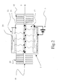
- Fig. 2 illustrates the second embodiment of the present invention, an OLED-pumped dye-doped fibre laser, where the OLED pumped region is enclosed between grating mirrors.
- the optional jacket layer is not depicted.
- a novel optical device comprising an optical cable or fibre 1 and an associated structure 2,3 is disclosed. It involves an optical fibre 1 pumped by a co-axial flexible light-emitting diode 2 (LED).
- the fibre can be a plastic optical fibre, a glass fibre, or another type of optical fibre.
- Optical fibres are known to be flexible.
- An optical cable or fibre 1 comprises an organic or inorganic core 11 doped with either fluorescent or phosphorescent impurities, called dyes (preferably organic dyes or metals, preferably rare earth metals like Erbium, Terbium, Europium, etc.) and located in a transparent envelope 12,13.
- the envelope comprises a cladding layer 12 and optionally an additional jacket layer 13 (part of the envelope and thus transparent).
- the jacket layer can improve the adhesion between the envelope and the flexible light emitting diode and can increase mechanical strength of the fibre.
- the envelope is coated with a coaxial mono- or multi-layer organic light-emitting diode 2.
- OLEDs have three prominent features namely (i) easy production of OLEDs with large active areas, (ii) possibility of producing non-planar light-emitting surfaces, and (iii) flexibility of OLEDs comparable with or even exceeding that of optical cables. It is the unique combination of those properties that allows to integrate an OLED essentially coaxially with an optical fibre as described in the present invention.
- the OLED according to the present invention has a transparent inner electrode 21 (e.g. Indium Tin Oxide (ITO)).
- the OLED has a reflective, preferably metallic (e.g. Al, Ca, Ag, Au,...), outer electrode 22.
- the active area 23 can be a mono layer or a multi layer structure.
- the active layer(s) can be made of organic materials, such as for example conjugated polymers as for instance polyphenylenevinylene (PPV) and derivatives thereof.
- the active layer(s) can also be made of small organic molecules as for instance Alq 3 .
- light emitted by the OLED can penetrate the optically passive transparent inner electrode 21 and envelope 12,13 and can excite dye molecules in the core 11 of the optical fibre.
- the light that does not pass through the fibre core 11 traverses the envelope 12,13 and the OLED stack of layers until it can be reflected by the outer reflecting electrode 22 of the OLED. Due to the Stokes shift the emitted light cannot be strongly absorbed in the active area 23 of the OLED.
- the envelope 12,13 is essentially transparent for this light. Therefore, multiple reflections are possible before the light ultimately penetrates into the fibre core 11. These multiple reflections enhance the light flux that finally penetrates into the fibre core 11 as compared to the light flux emitted by the OLED surface along the direction to the fibre core.
- the light emitted by the OLED can be advantageously chosen to lie in the absorption band of dye dopants that are incorporated in the fibre core 11. Within the fibre core 11, the OLED-pumped light therefore excites said dye dopants that subsequently emit photons along various directions. A fraction of the light emitted by said dopants will be wave-guided within the optical fibre.
- Enhanced emission causes stimulated emission in the fibre core 11 and the integrated device can be used for optical signal generation, regeneration and amplification.
- mirrors 41, 42 are applied to both ends of the pumped fibre region.
- Such mirrors can be formed by technologies known to a person skilled in the art, for example by etching a pair of fibre phase gratings into the core 11 of the fibre that act like Bragg gratings or by depositing a reflective material on cleaved fibre ends.
- One of both mirrors can be partially transparent 42.
- optical gain can be provided into the cavity formed between the mirrors 41,42. This threshold can be reached at higher light fluxes generated by the OLED. Lasing output 5 can then be achieved in the OLED-pumped doped fibre.
- An aspect of the first and second embodiments of the present invention is that the ratio of maximum pumping light flux that finally penetrates into the fibre core to the light flux emitted by the OLED surface (called efficiency) can be modelled as a function of the ratio of the perimeter of the envelope 12,13 to the perimeter of the core 11, Pe/Pc.
- This ratio can be designed to be one or several orders of magnitude by varying the radii of the core (Rc) and the envelope (Re). To a certain extend, the invention thus allows to control the amount of flux of light absorbed in the fibre core 11.
- Another aspect of the first and second embodiments of the present invention is that theoretically some light rays of the pumping OLED can resonate in a mode that never traverses the core of the fibre.
- the presence of such modes can be maximally avoided, resulting in a further increased light flux of pumping light in the fibre core.
- imperfections in the coaxial arrangement of the OLED with respect to the fibre core can be introduced. In practice such imperfection, although small, are always present. These imperfections can also be created on purpose, by for instance roughening the outer surface of the envelope before deposition of the OLED, or by roughening at least 1 layer which is part of the integrated optical device, before adding the next layer(s). In those cases, the surface structure of the outer reflecting layer changes the angle of propagation at every reflection.
- the OLED device has a transparent outer electrode and comprises an additional outer layer on top of the outer electrode, which is reflective. Light produced by the OLED can then pass through the transparent outer electrode and reflect from this additional reflective outer layer.
- Yet another aspect of the present invention is that the light-source can increase mechanical strength of the optical cable.
- optical devices according to the first and second embodiments of the present invention can be produced by rotating the optical fibre (for which production in known in the art) while adding deposition material on the fibre in a controlled way such that homogeneous layers can be achieved.
- optical devices according to the present invention can be used for introscopic purposes as for instance endoscopic purposes.
Landscapes
- Physics & Mathematics (AREA)
- Optics & Photonics (AREA)
- Electromagnetism (AREA)
- Engineering & Computer Science (AREA)
- Plasma & Fusion (AREA)
- General Physics & Mathematics (AREA)
- Microelectronics & Electronic Packaging (AREA)
- Light Guides In General And Applications Therefor (AREA)
Abstract
Description
- an optical cable, having an axial symmetry, comprising a core, doped with phosphorescent or fluorescent impurities, and a transparent envelope;
- said transparent envelope further comprising a cladding layer and optionally a jacket layer, surrounding said cladding layer;
- an associated light source, comprising:
- an inner electrode,
- an outer electrode, and
- an active area, located between said inner electrode and said outer electrode;
Claims (14)
- Optical device, comprising:an optical cable (1), having an axial symmetry, comprising a core (11), doped with phosphorescent or fluorescent impurities, and a transparent envelope (12,13);said transparent envelope (12,13) further comprising a cladding layer (12) and optionally a jacket layer (13), surrounding said cladding layer (12);an associated light source (2), comprising:whereinan inner electrode (21),an outer electrode (22), andan active area, located between said inner electrode and said outer electrode (23);said light source (2) and said optical cable (1) are integrated;said light source (2) has an axial symmetry and is positioned coaxially to said optical cable (1); andsaid inner electrode (21) is transparent, such that light, generated in said active area (23) can propagate outside said light source (2) and into said optical cable (1).
- Device according to claim 1, wherein said outer electrode (22) is reflective.
- Device according to claim 1 to 2, wherein said light-source (2) is flexible.
- Device according to claim 1 to 3, wherein said light-source is a mono- or multi-layer organic light-emitting diode (OLED).
- Device according to claim 1, 3 and 4, whereby said outer electrode (22) is transparent and said light-source comprises an additional outer layer which is reflective.
- Device according to claim 1 to 5, further comprising mirrors (41,42) on both sides of the optically pumped region, one mirror being not transparent (41), the other mirror being partially transparent.
- Device according to claim 1 to 6, wherefore the efficiency of absorption of light in said core (11), said light produced by said light source (2), is a function of Pe/Pc.
- Device according to claim 7, wherefore said efficiency is controlled by choosing Pe/Pc appropriately.
- Device as recited in claim 1 to 5, used as an optical signal generator.
- Device as recited in claim 9, whereby said optical signal is constant.
- Device as recited in claim 1 to 5, used as an optical signal amplifier or repeater.
- Device according to claim 6, wherein said device is a laser.
- Device according to claim 1 to 12, used for introspection.
- Device according to claim 1 to 13, used for endoscopy.
Priority Applications (2)
| Application Number | Priority Date | Filing Date | Title |
|---|---|---|---|
| EP03447004A EP1437616A1 (en) | 2003-01-10 | 2003-01-10 | Optical fiber with integrated pump light source |
| US10/753,091 US7079748B2 (en) | 2003-01-10 | 2004-01-07 | Integrated optical device and method of making the same |
Applications Claiming Priority (1)
| Application Number | Priority Date | Filing Date | Title |
|---|---|---|---|
| EP03447004A EP1437616A1 (en) | 2003-01-10 | 2003-01-10 | Optical fiber with integrated pump light source |
Publications (1)
| Publication Number | Publication Date |
|---|---|
| EP1437616A1 true EP1437616A1 (en) | 2004-07-14 |
Family
ID=32479994
Family Applications (1)
| Application Number | Title | Priority Date | Filing Date |
|---|---|---|---|
| EP03447004A Ceased EP1437616A1 (en) | 2003-01-10 | 2003-01-10 | Optical fiber with integrated pump light source |
Country Status (1)
| Country | Link |
|---|---|
| EP (1) | EP1437616A1 (en) |
Cited By (3)
| Publication number | Priority date | Publication date | Assignee | Title |
|---|---|---|---|---|
| EP1954101A4 (en) * | 2005-10-20 | 2009-01-28 | Sumitomo Chemical Co | LIGHT EMITTING ELEMENT |
| CN103633539A (en) * | 2013-11-29 | 2014-03-12 | 清华大学 | Embedded gas discharge pumping rare earth particle-doped gain optical fiber |
| WO2014027205A3 (en) * | 2012-08-17 | 2014-05-15 | The Secretary Of State For Business Innovation & Skills Of Her Majesty's Britannic Government | Maser assembly |
Citations (4)
| Publication number | Priority date | Publication date | Assignee | Title |
|---|---|---|---|---|
| US5892876A (en) * | 1995-10-31 | 1999-04-06 | Alcatel Submarine Networks | Optical fiber including a fluorescent dopant |
| EP0989639A2 (en) * | 1998-09-23 | 2000-03-29 | Walter Langner | LED pumped high power laser |
| US6167075A (en) * | 1996-07-09 | 2000-12-26 | Sdl, Inc. | High power, reliable optical fiber pumping system with high redundancy for use in lightwave communication systems |
| EP1180805A2 (en) * | 2000-08-17 | 2002-02-20 | General Electric Company | An oled fiber light source |
-
2003
- 2003-01-10 EP EP03447004A patent/EP1437616A1/en not_active Ceased
Patent Citations (4)
| Publication number | Priority date | Publication date | Assignee | Title |
|---|---|---|---|---|
| US5892876A (en) * | 1995-10-31 | 1999-04-06 | Alcatel Submarine Networks | Optical fiber including a fluorescent dopant |
| US6167075A (en) * | 1996-07-09 | 2000-12-26 | Sdl, Inc. | High power, reliable optical fiber pumping system with high redundancy for use in lightwave communication systems |
| EP0989639A2 (en) * | 1998-09-23 | 2000-03-29 | Walter Langner | LED pumped high power laser |
| EP1180805A2 (en) * | 2000-08-17 | 2002-02-20 | General Electric Company | An oled fiber light source |
Cited By (8)
| Publication number | Priority date | Publication date | Assignee | Title |
|---|---|---|---|---|
| EP1954101A4 (en) * | 2005-10-20 | 2009-01-28 | Sumitomo Chemical Co | LIGHT EMITTING ELEMENT |
| US8324799B2 (en) | 2005-10-20 | 2012-12-04 | Sumitomo Chemical Company, Limited | Light emitting device |
| WO2014027205A3 (en) * | 2012-08-17 | 2014-05-15 | The Secretary Of State For Business Innovation & Skills Of Her Majesty's Britannic Government | Maser assembly |
| JP2015529391A (en) * | 2012-08-17 | 2015-10-05 | ザ セクレタリー オブ ステイト フォー ビジネス イノベーション アンド スキルズ オブ ハー マジェスティズ ブリタニック ガバメントThe Secretary Of State For Business Innovation And Skills Of Her Majesty’S Britannic Government | Maser device |
| US9608396B2 (en) | 2012-08-17 | 2017-03-28 | The Secretary Of State For Business, Innovation And Skills Of Her Magesty's Britannic Government | Maser assembly |
| EP3557703A1 (en) * | 2012-08-17 | 2019-10-23 | NPL Management Limited | Maser assembly |
| CN103633539A (en) * | 2013-11-29 | 2014-03-12 | 清华大学 | Embedded gas discharge pumping rare earth particle-doped gain optical fiber |
| CN103633539B (en) * | 2013-11-29 | 2015-12-30 | 清华大学 | Embedded gas discharge pumped mixes rare earth ion gain fibre |
Similar Documents
| Publication | Publication Date | Title |
|---|---|---|
| EP0743722B1 (en) | High-power pumping of three-level optical fiber laser amplifier | |
| US8611003B2 (en) | Double clad fiber laser device | |
| TWI420147B (en) | White light-emitting device using fluorescent fiber | |
| US7079748B2 (en) | Integrated optical device and method of making the same | |
| JPH09283847A (en) | Semiconductor laser module | |
| CN107179583A (en) | Optical coupling connector, optically coupled system and waveguide coupling process | |
| US8902494B2 (en) | Amplification optical fiber with optical component and fiber laser device including the same | |
| US20060012853A1 (en) | Low cost optical amplifier | |
| EP1523075A2 (en) | High power fibre laser with eye safe wavelengths | |
| EP3633317A2 (en) | Systems and methods for end pumped laser mirror stack assemblies | |
| CN1602568A (en) | Optical amplifier with distributed evanescently-coupled pump | |
| KR20080078880A (en) | Optically Pumped Waveguide Laser with Tapered Waveguide Sections | |
| JP2007157764A (en) | Multi-wavelength laser light source using fluorescent fiber | |
| US7362496B2 (en) | Fiber gain medium and method of coupling pump energy into the same | |
| US5235604A (en) | Optical amplifier using semiconductor laser as multiplexer | |
| CN100416947C (en) | Optical amplifier with transverse pump | |
| CN1602567A (en) | Optical amplifier with multiple wavelength pump | |
| US20050088723A1 (en) | Waveguide optical amplifier | |
| TWI420168B (en) | Shell-type pump-eductive evanescent field gain fiber | |
| Kurkov et al. | High-power Yb-doped double-clad fiber lasers for a range of 0.98-1.04 µm. | |
| JPH1187811A (en) | Laser device | |
| JP2007103704A (en) | Light emitting device, laser display, endoscope | |
| JPH06216408A (en) | Glass light emitting element | |
| WO2005017567A3 (en) | Optical fiber amplifier with fully integrated pump source | |
| JP2004079834A (en) | Waveguide type optical amplifier |
Legal Events
| Date | Code | Title | Description |
|---|---|---|---|
| PUAI | Public reference made under article 153(3) epc to a published international application that has entered the european phase |
Free format text: ORIGINAL CODE: 0009012 |
|
| AK | Designated contracting states |
Kind code of ref document: A1 Designated state(s): AT BE BG CH CY CZ DE DK EE ES FI FR GB GR HU IE IT LI LU MC NL PT SE SI SK TR |
|
| AX | Request for extension of the european patent |
Extension state: AL LT LV MK RO |
|
| 17P | Request for examination filed |
Effective date: 20040907 |
|
| 17Q | First examination report despatched |
Effective date: 20041001 |
|
| AKX | Designation fees paid |
Designated state(s): AT BE BG CH CY CZ DE DK EE ES FI FR GB GR HU IE IT LI LU MC NL PT SE SI SK TR |
|
| 17Q | First examination report despatched |
Effective date: 20041001 |
|
| STAA | Information on the status of an ep patent application or granted ep patent |
Free format text: STATUS: THE APPLICATION HAS BEEN REFUSED |
|
| 18R | Application refused |
Effective date: 20080201 |