EP1437577B1 - Integral dual technology flow sensor - Google Patents
Integral dual technology flow sensor Download PDFInfo
- Publication number
- EP1437577B1 EP1437577B1 EP03021337A EP03021337A EP1437577B1 EP 1437577 B1 EP1437577 B1 EP 1437577B1 EP 03021337 A EP03021337 A EP 03021337A EP 03021337 A EP03021337 A EP 03021337A EP 1437577 B1 EP1437577 B1 EP 1437577B1
- Authority
- EP
- European Patent Office
- Prior art keywords
- sensor
- flow
- sensing
- displacement
- change
- Prior art date
- Legal status (The legal status is an assumption and is not a legal conclusion. Google has not performed a legal analysis and makes no representation as to the accuracy of the status listed.)
- Expired - Lifetime
Links
- 238000005516 engineering process Methods 0.000 title description 2
- 230000009977 dual effect Effects 0.000 title 1
- 238000005452 bending Methods 0.000 claims abstract description 93
- 238000006073 displacement reaction Methods 0.000 claims abstract description 78
- 230000004044 response Effects 0.000 claims abstract description 24
- 230000008859 change Effects 0.000 claims description 43
- 238000000034 method Methods 0.000 claims description 25
- 239000010410 layer Substances 0.000 claims description 23
- 238000002955 isolation Methods 0.000 claims description 9
- 239000002346 layers by function Substances 0.000 claims description 8
- 229910052710 silicon Inorganic materials 0.000 claims description 7
- 239000010703 silicon Substances 0.000 claims description 7
- BASFCYQUMIYNBI-UHFFFAOYSA-N platinum Chemical compound [Pt] BASFCYQUMIYNBI-UHFFFAOYSA-N 0.000 claims description 6
- VYPSYNLAJGMNEJ-UHFFFAOYSA-N Silicium dioxide Chemical compound O=[Si]=O VYPSYNLAJGMNEJ-UHFFFAOYSA-N 0.000 claims description 4
- 238000000206 photolithography Methods 0.000 claims description 4
- 229910021420 polycrystalline silicon Inorganic materials 0.000 claims description 4
- 239000011521 glass Substances 0.000 claims description 3
- 239000007788 liquid Substances 0.000 claims description 3
- 229910052697 platinum Inorganic materials 0.000 claims description 3
- 239000010409 thin film Substances 0.000 claims description 3
- 229910052581 Si3N4 Inorganic materials 0.000 claims description 2
- 230000001154 acute effect Effects 0.000 claims description 2
- 230000005669 field effect Effects 0.000 claims description 2
- HQVNEWCFYHHQES-UHFFFAOYSA-N silicon nitride Chemical compound N12[Si]34N5[Si]62N3[Si]51N64 HQVNEWCFYHHQES-UHFFFAOYSA-N 0.000 claims description 2
- 229910052814 silicon oxide Inorganic materials 0.000 claims description 2
- 239000002002 slurry Substances 0.000 claims description 2
- 230000008878 coupling Effects 0.000 claims 2
- 238000010168 coupling process Methods 0.000 claims 2
- 238000005859 coupling reaction Methods 0.000 claims 2
- 239000007789 gas Substances 0.000 claims 1
- 238000005259 measurement Methods 0.000 description 14
- 230000008569 process Effects 0.000 description 10
- 239000000463 material Substances 0.000 description 5
- PXHVJJICTQNCMI-UHFFFAOYSA-N Nickel Chemical compound [Ni] PXHVJJICTQNCMI-UHFFFAOYSA-N 0.000 description 4
- XUIMIQQOPSSXEZ-UHFFFAOYSA-N Silicon Chemical compound [Si] XUIMIQQOPSSXEZ-UHFFFAOYSA-N 0.000 description 4
- 238000010586 diagram Methods 0.000 description 4
- 239000012530 fluid Substances 0.000 description 4
- 230000004048 modification Effects 0.000 description 4
- 238000012986 modification Methods 0.000 description 4
- 238000012545 processing Methods 0.000 description 4
- 230000035945 sensitivity Effects 0.000 description 4
- 238000012937 correction Methods 0.000 description 3
- 238000005530 etching Methods 0.000 description 3
- 101150042711 adc2 gene Proteins 0.000 description 2
- 238000013459 approach Methods 0.000 description 2
- 230000002457 bidirectional effect Effects 0.000 description 2
- 230000000295 complement effect Effects 0.000 description 2
- 230000001143 conditioned effect Effects 0.000 description 2
- 238000000151 deposition Methods 0.000 description 2
- 230000000694 effects Effects 0.000 description 2
- 229910044991 metal oxide Inorganic materials 0.000 description 2
- 150000004706 metal oxides Chemical class 0.000 description 2
- 238000005459 micromachining Methods 0.000 description 2
- 229910052759 nickel Inorganic materials 0.000 description 2
- 229920005591 polysilicon Polymers 0.000 description 2
- 239000004065 semiconductor Substances 0.000 description 2
- 101100434411 Saccharomyces cerevisiae (strain ATCC 204508 / S288c) ADH1 gene Proteins 0.000 description 1
- 101150102866 adc1 gene Proteins 0.000 description 1
- 238000000137 annealing Methods 0.000 description 1
- 230000003466 anti-cipated effect Effects 0.000 description 1
- 230000001419 dependent effect Effects 0.000 description 1
- 230000008021 deposition Effects 0.000 description 1
- 238000001312 dry etching Methods 0.000 description 1
- 238000009713 electroplating Methods 0.000 description 1
- 230000007613 environmental effect Effects 0.000 description 1
- 230000001747 exhibiting effect Effects 0.000 description 1
- 239000010408 film Substances 0.000 description 1
- 230000006870 function Effects 0.000 description 1
- 238000009434 installation Methods 0.000 description 1
- 230000010354 integration Effects 0.000 description 1
- 238000005468 ion implantation Methods 0.000 description 1
- 238000004519 manufacturing process Methods 0.000 description 1
- 229910052751 metal Inorganic materials 0.000 description 1
- 239000002184 metal Substances 0.000 description 1
- 239000000203 mixture Substances 0.000 description 1
- 150000004767 nitrides Chemical class 0.000 description 1
- 230000010355 oscillation Effects 0.000 description 1
- 238000001953 recrystallisation Methods 0.000 description 1
- 230000000717 retained effect Effects 0.000 description 1
- 235000012239 silicon dioxide Nutrition 0.000 description 1
- 239000000377 silicon dioxide Substances 0.000 description 1
- 239000000758 substrate Substances 0.000 description 1
- 238000001039 wet etching Methods 0.000 description 1
Images


Classifications
-
- G—PHYSICS
- G01—MEASURING; TESTING
- G01F—MEASURING VOLUME, VOLUME FLOW, MASS FLOW OR LIQUID LEVEL; METERING BY VOLUME
- G01F1/00—Measuring the volume flow or mass flow of fluid or fluent solid material wherein the fluid passes through a meter in a continuous flow
- G01F1/05—Measuring the volume flow or mass flow of fluid or fluent solid material wherein the fluid passes through a meter in a continuous flow by using mechanical effects
- G01F1/20—Measuring the volume flow or mass flow of fluid or fluent solid material wherein the fluid passes through a meter in a continuous flow by using mechanical effects by detection of dynamic effects of the flow
- G01F1/28—Measuring the volume flow or mass flow of fluid or fluent solid material wherein the fluid passes through a meter in a continuous flow by using mechanical effects by detection of dynamic effects of the flow by drag-force, e.g. vane type or impact flowmeter
Definitions
- the present invention generally relates to a fluid sensor for measuring the flow of a gaseous media, and relates more particularly to a universal flow sensor that is suitable for use in pneumatic circuits exhibiting a wide range of flow rates without substantial modification.
- the first is inferential flow measurement, which senses a difference in pressure across an orifice restriction.
- the second method uses a thermal sensor, which is also referred to as a constant temperature anemometer, to monitor temperature changes that are dependent upon the speed of the media, as described in U.S. Patent No. 6,470,741 to Fathollahzadeh.
- the third method utilizes displacement sensors that detect mechanical displacement of a portion of the sensor caused by the flow of media.
- Inferential flow measurement generally requires two pressure sensors and a restriction in flow.
- a temperature sensor is also typically required with this method to compensate for variations in pressure due solely to temperature fluctuations.
- the requirement of multiple sensors substantially increases failure rate and installation cost.
- thermal sensors are used for lower flow rates while displacement sensors are used for relatively higher flow rates.
- Selection of the most appropriate flow sensor for a particular application requires a detailed knowledge of the anticipated range of measurements, the potential physical characteristics of the media, such as pressure, temperature, and the like, and the environmental characteristics of the location in which the media is to be measured. Accordingly, use of either thermal sensors or displacement sensors generally requires a customized solution for each particular application.
- U.S. Patent No. 4,565,098 to Herzl discloses a hybrid sensing system for vortex-type flowmeter in which fluidic oscillations are generated at a frequency depending on the flow rate of the fluid being metered.
- the system includes a thermal sensor inside a fluid channel and a force sensor outside a flow pipe.
- a flow stream flowing through the flow pipe impinges on a unit that is pivotally supported by torque tubes and coupled to an external torque transducer.
- the transducer oscillates about its pivot axis following a motion of the unit inside the flow pipe thereby producing a signal with a frequency that is proportional to the flow rate of the fluid being metered.
- the signals of the torque transducer or force sensor and of a thermal sensor located on the unit inside the flow pipe are compared in order to select a signal that is indicative of the flow rate in the flow pipe.
- a flow sensor formed in accordance with one form of the present invention which incorporates some of the preferred features, includes a mounting plate, bending plate, and sensing assembly.
- the mounting plate is adapted to be mounted to an internal surface of a conduit, which directs the flow of a gaseous medium.
- the bending plate is flexibly coupled to the mounting plate and is displaced in response to the flow of gas in the conduit.
- the sensing assembly is positioned on the bending plate and includes at least one sensor adapted for sensing temperature changes in response to the flow of gas during a thermal mode.
- the sensing assembly includes at least one sensor adapted for sensing displacement of the bending plate in response to the flow of gas during a displacement mode.
- the temperature outputs a thermal mode signal representative of a change in temperature in response to the flow of gas.
- the displacement sensor outputs a displacement mode signal representative of a change in mechanical stress in response to displacement of the bending plate due to the flow of gas.
- a flow sensing system formed in accordance with the present invention which incorporates some of the preferred features, includes the flow sensor described above, a processor, memory, and a computer.
- the processor is responsive to the thermal and displacement mode signals and the memory is operatively coupled to the processor.
- the computer is operatively coupled to the processor and controls calibration of the flow sensor in both the thermal and displacement modes.
- a universal flow sensor formed in accordance with the present invention preferably includes a sensor assembly that is switched between a constant temperature anemometer or thermal mode for sensing low values of flow and a displacement mode for sensing substantially higher values of flow of a gaseous medium.
- the universal flow sensor can also be used to sense the flow of liquids, compositions, slurries, and the like if the sensing elements are appropriately protected.
- the sensor assembly is preferably switched between the thermal and displacement modes by a multiplexing system that acquires measurement data in each of the modes sequentially or in a dedicated manner.
- Figure 1 is a side cross-sectional view of the universal flow sensor 10, which is preferably mounted within a conduit or air hose 12.
- the air hose 12 guides the flow of gas in the direction of an arrow 14 which can also be denominated as arrow "airflow”.
- the flow sensor 10 preferably includes a mounting plate 16 and a bending plate 18.
- the mounting plate 16 is preferably affixed or mounted to a wall of the air hose 12.
- the bending plate 18 preferably makes an acute angle with a wall of the air hose 12 and an obtuse angle with the mounting plate 16.
- the bending plate 18 is preferably surrounded by the flow of gas and may have a special shape to increase mechanical displacement of the bending plate 18 in response to this flow.
- a sensor assembly 20 is preferably mounted on that side of the bending plate 18 that opposes the direction of flow, as indicated by arrow 14.
- the sensor assembly 20 preferably includes one or more sensors.
- the sensors are resistors, which are made from the same or similar material, that operate as strain gauges. That is, the resistors exhibit a change in resistance that is proportional to the elongation caused by bending the bending plate 18 by the flow of gas.
- One or more of the resistors preferably also provide for temperature compensation.
- the sensors in the sensor assembly 20 are preferably connected in a full bridge configuration, which measures displacement of the bending plate 18 caused by flow in the air hose 12 during the displacement mode. At least a portion of the sensor assembly 20 is also preferably exposed to the flow of gas for use as a constant temperature anemometer during the thermal mode.
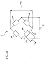
- Figure 2a is a schematic diagram showing the preferred interconnections between individual sensors in the sensor assembly 20.
- the sensor assembly 20 preferably includes four (4) resistors or sensors 20A, 20B, 20C, and 20D, which are preferably arranged on that side of the bending plate 18 facing the arrow 14 shown in Figure 1.
- a power supply 22 includes a first terminal and a second terminal.
- the first terminal of the power supply 22 is preferably connected to a node connecting sensors 20B and 20C, and the second terminal is preferably connected to a node connecting sensors 20A and 20D.
- Switches 24A and 24B which may be implemented using, for instance, electromechanical relays, preferably isolate both terminals of sensor 20C from the bridge circuit, which enables sensor 20C to operate as a constant temperature anemometer in the thermal mode.
- a voltage U ML which is preferably measured across the terminals of sensor 20C while sensor 20C is disconnected from the bridge circuit by switches 24A and 24B, represents a change in resistance as a result of the heat transferred by the gas flow, and thus provides a measure of gaseous flow in the air hose 12 during the thermal mode.
- a voltage U MH is preferably measured across a node connecting sensors 20A and 20B, and a node connecting sensors 20C and 20D.
- the voltage U MH preferably represents a change in resistance caused by mechanical stress experienced by sensors 20B and 20D during the displacement mode.
- Sensors 20A and 20C are preferably used for temperature compensation in the displacement mode.
- the flow sensor 10 formed in accordance with the present invention enables the measurement of a relatively lower rate of flow during the thermal mode and a relatively higher rate of flow during the displacement mode.
- the two switches isolating sensor 20C from the bridge circuit are preferably implemented as two solid-state switches, such as two field effect transistors (FET) 26A and 26B, as shown in Figure 2b.
- the FET switches 26A and 26B are controlled by corresponding gate voltage signals 28A and 28B, which are preferably connected to a signal processing circuit that selects either the thermal mode or displacement mode.
- Sensors 20B and 20D are preferably arranged on the bending plate 18 such that sensors 20B and 20D experience mechanical stress caused by distortion of the bending plate 18 in response to the flow of gas during the displacement mode.
- both sensors 20B and 20D are preferably in opposing branches of the bridge circuit, as shown in Figures 2a and 2b.
- Sensors 20A and 20C are preferably arranged on the bending plate such that sensors 20A and 20C do not experience a substantial amount of stress caused by distortion of the bending plate 18 in response to the flow of gas during the displacement mode. Both sensors 20A and 20C are preferably also in opposing branches of the full bridge circuit, as shown in Figures 2a and 2b. Sensors 20A and 20C preferably exhibit the same nominal resistance as sensors 20B and 20D and are preferably used for temperature compensation in the full bridge circuit.
- sensor 20C may be left connected to the remaining resistors in the bridge circuit during the thermal mode. In this embodiment, sensor 20C is retained in the bridge circuit during both the thermal mode and the displacement mode.
- the switches 24A and 24B ( Figure 2a), FET switches 26A and 26B ( Figure 2b), and gate voltage signals 28A and 28B ( Figure 2b) are preferably not required in this embodiment.
- cross-sensitivity of the displacement sensors 20B and 20D is relatively low at low flow rates, which correspond to a nominal or expected range of measurements in the thermal mode.
- cross-sensitivity is defined herein as the effect that mechanical stress has on displacement sensors 20B and 20D during low flow measurements in the thermal mode while sensor 20C is connected to the bridge circuit.
- a characteristic curve, or a lookup table representing such a curve, which indicates the cross sensitivity of the displacement sensors in the thermal mode, is preferably programmed into non-volatile memory, such as electrically erasable programmable read only memory (EEPROM), if such errors cannot be neglected. This information can then be used to compensate for cross sensitivity errors when determining the value of U ML during measurements in the thermal mode.
- non-volatile memory such as electrically erasable programmable read only memory (EEPROM)
- MEMS Micro-Electro-Mechanical System
- the mechanical and electrical elements can either have the function of a sensor or an actuator.
- the electronic circuits are fabricated using integrated circuit (IC) processes, such as CMOS (Complementary Metal Oxide Semiconductor), bipolar, or BICMOS (Bipolar Complementary Metal Oxide Semiconductor) processes.
- CMOS Complementary Metal Oxide Semiconductor
- bipolar Bipolar Complementary Metal Oxide Semiconductor
- BICMOS Bipolar Complementary Metal Oxide Semiconductor
- the micromechanical components are fabricated using compatible micromachining processes, which selectively etch away portions of a silicon wafer or add new structural layers to form mechanical and electromechanical devices.
- the flow sensor 10 shown in Figure 1 includes the sensor assembly 20 mounted on the bending plate 18, which is preferably made from either silicon, glass, or a metal, such as Covar TM .
- the bending plate 18 preferably provides support for a functional layer 21 and one or more isolation layers 23 of the sensor assembly 20.
- the functional layer preferably includes sensors 20A, 20B, 20C, and 20D.
- the functional layer 21 of the sensor assembly 20 is preferably isolated from the bending plate 18 by one or more isolation layers 23 that are made from materials that are compatible with CMOS processes, such as silcon oxide or silcon nitride.
- the bending plate 18 is preferably made from polycrystalline silicon if the mounting plate 16 is made from silicon or glass. However, if the mounting plate 16 is metallic, the bending plate 18 is preferably made from the same material as the mounting plate 16.
- the functional and isolation layers are deposited on a structured sacrificial layer, which is preferably either silicon oxide or silicon nitride.
- a structured sacrificial layer which is preferably either silicon oxide or silicon nitride.
- small etch channels can be implemented in the functional and isolation layers using photolithography. These channels enable an etching gas or liquid to reach the sacrificial layer and remove the sacrificial layer while retaining the functional and isolation layers.
- the sacrificial layer is preferably removed in an etching process.
- a predefined stress is preferably applied to the layer building up the bending plate.
- An initial bending of the bending plate is preferably created either by varying a doping concentration or implementing a stress gradient using different annealing profiles.
- a constant stress gradient is preferably implemented in the bending plate 16 using at least one of two technological processes.
- a multistep deposition of an ⁇ -silicon or polysilicon layer is followed by supplementary implementation of a stress gradient by doping or ion implantation.
- the second approach involves depositing nickel using an electroplating process with various current densities followed by a supplementary step of laser recrystallization.
- the choice of the process of releasing the sacrificial layer depends on the choice of the material of the functional and sacrificial layers. For instance, if the functional and isolation layers are ⁇ -silicon, polysilicon, or nickel, the sacrificial layer is preferably silicon dioxide.
- Release of the mounting plate 16 is preferably performed by etching the sacrificial layer. Dry or wet etching processes are may be used.
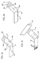
- Sensors 20B and 20D are preferably located on the functional layer 21 in an area of maximum stress during displacement of the bending plate 18, as shown in Figure 3a.
- Sensors 20B and 20D are preferably resistors based on either a thin film polycrystalline or platinum layer technology and are deposited using photolithography techniques.
- sensors 20B and 20D are preferably made of the same material as sensors 20A and 20C and, as discussed above, are preferably active and used to indicate stress during the displacement mode. Sensors 20A and 20C are located in an area of the bending plate 18 experiencing substantially lower stress due to displacement of the bending plate, as shown in Figure 3a.
- sensors 20A and 20C are preferably passive or used for temperature compensation during the displacement mode. However, during the thermal mode, sensor 20C is preferably active and used as a hot film element sensor. As described above, in order to reduce cross-sensitivity due to mechanical stress during the displacement mode, sensor 20C is preferably disconnected from the remaining elements of the bridge circuit by electronic switches, such as switches 24A and 24B shown in Figure 2a or FET switches 28A and 28B shown in Figure 2b.
- sensors 20B and 20D are preferably located near and perpendicular to a bending axis 30, which separates the bending plate 18 from the mounting plate 16.
- Sensors 20A and 20C are preferably located in an area of the mounting plate 18 that experiences substantially lower stress, which is farther away from the bending axis 30 and parallel to this axis.
- only one sensor 20B is preferably used to detect distortion of the bending plate 18 during the displacement mode.
- Sensor 20B is preferably located in an area of maximum stress, which is near the bending axis 30 and preferably perpendicular to this axis.
- the sensor 20B is preferably made from either thin film polycrystalline or platinum layers and deposited using photolithography techniques, as are the remaining sensors 20A, 20C, and 20D in the half bridge embodiment. Sensors 20A, 20C, and 20D are preferably located in an area of the bending plate 16 that experiences relatively lower stress due to displacement, which is farther away from the axis of bending 30 and parallel to this axis, as shown in Figure 3b.
- Sensors 20A, 20C, and 20D are preferably passive or used for temperature compensation during the displacement mode.
- sensor 20C is preferably active, as described above in relation to the full bridge embodiment of the present invention, and sensors 20A, 20B, and 20D are passive or used for temperature compensation.
- the bending plate 18 may include a blade 32 that is preferably positioned to increase the drag, and thus effect of gas flow on the bending plate 18.
- the blade 32 preferably increases the degree of bending of the bending plate 18 in response to the flow.
- FIG 4 shows a signal processing for the sensor formed in accordance with the present invention.
- the node connecting sensors 20A and 20B and the node connecting sensors 20C and 20D are preferably connected to the positive and negative terminals of the amplifier 34.
- the amplifier 34 preferably translates the output signal U MH from the bridge circuit shown in Figures 2a and 2b to a conditioned analog output signal.
- the analog signal outputted from the amplifier 34 is preferably further amplified by amplifier 35 and converted into a digital signal for correction, compensation, and/ or calibration of its parameters, such as sensor offset, gain, temperature sensitivity, and non-linearity, by inputting the amplified signal into an analog-to-digital converter input ADC1 of a microcontroller 36, which then performs compensating and/or corrective algorithms.
- the microcontroller 36 is preferably linked to a personal computer 40 with a bidirectional serial interface 38.
- the serial interface 38 preferably enables the personal computer 40 to control the calibration procedure, at least a portion of which is performed in the microcontroller 36.
- the calibration procedure preferably involves reading uncalibrated sensor and temperature values from the microcontroller 36, calculating a set of calibration coefficients, and programming the coefficients into non-volatile memory 42 coupled to the microcontroller 36. These coefficients are then available for use in compensation by the microcontroller 36 for subsequent measurements.
- Signal processing for the thermal mode is also preferably implemented using an instrumentation amplifier 44 shown in Figure 4.
- the terminals of sensor 20C are preferably connected to the positive and negative terminals of the amplifier 44.
- the amplifier 44 preferably translates the output signal U ML from the bridge circuit to a conditioned analog output signal.
- the analog output signal is preferably further amplified by amplifier 45 and converted into a digital signal for correction and compensation of its parameters, by inputting the analog signal from the amplifier 44 into a second analog-to-digital converter input ADC2 of the microcontroller 36, as shown in Figure 4, which performs compensation and/or corrective algorithms.
- the temperature of the sensor 20C is maintained at a substantially constant value by providing a variable current through the feedback loop. As the flow of gas increases, the current must also increase to maintain a constant temperature.
- the voltage inputted to the analog-to-digital converter input ADC2 of the microcontroller 36 is representative of flow.
- digital correction and compensation is possible for sensor offset, gain, temperature sensitivity, and non-linearity by the microcontroller 36 operating in accordance with calibration coefficients stored in memory 42 under the control of the personal computer 40 over the bidirectional serial interface 38.
- the sensors 20A, 20B, 20C, and 20D and the interconnections between these sensors are preferably located on the bending plate 18 shown in Figure 1.
- Any additional components such as the switches 24A, 24B, 26A, 26B (also shown in Figures 2a and 2b); amplifiers 34, 35, 44, 45; microcontroller 36, memory 42, and power supply 22, are preferably not located on the bending plate 18 and even more preferably would be located external to the conduit 12 so as not to be subject to physical conditions within the conduit 12, such as airflow.
- the positioning of any or all of the above-identified components within the conduit 12, on the bending plate 18, and/or on the mounting plate 16 is considered to be well within the scope of the present invention.
- Electrical connections between the components located on the bending plate 18 and those located external to the bending plate 18 are preferably provided through interconnection with electrical contacts 46 shown in Figure 3c.
- one of the contacts 46 shown in Figure 3c is preferably electrically coupled to each of the nodes connecting the sensors 20A, 20B, 20C, 20D; the terminals of sensor 20C; and the coils of switches 24A, 24B, which results in six (6) total contacts.
- one of the contacts 46 shown in Figure 4 is preferably electrically coupled to each of the nodes connecting the sensors 20A, 20B, 20C, 20D; the terminals of sensor 20C; and the gates of FET switches 26A, 26B, which also results in eight (8) total contacts.
- one of the contacts 46 shown in Figure 3c is preferably electrically coupled to each of the nodes connecting the sensors 20A, 20B, 20C, 20D and the terminals of sensor 20C, which results in only six (6) total contacts.
- one of the contacts 46 shown in Figure 4 is preferably electrically coupled to each of the nodes connecting the sensors 20A, 20B, 20C, 20D and the terminals of sensor 20C, which also results in only six (6) total contacts.
- the flow sensor may be incorporated into an in-line module, to which segments of the conduit 12 are attached. Additional components and wiring to these components would then preferably be located internal and/or external to the module. Alternatively, the flow sensor may be mounted by any known means to an internal surface of the conduit, as shown in Figure 5b. Interconnection between components on the flow sensor and components external to the conduit 12 would preferably be made using wires 50 extending from contacts 46 on the flow sensor through a sealed orifice 52 in the conduit to components located external to the conduit 12.
- the universal flow sensor and system formed in accordance with the present invention are generically applicable and utilize both thermal sensing and displacement sensing to measure flow over an extended range of measurement parameters without requiring substantial modifications.
- the flow sensor and system are also able to multiplex flow rate measurement information obtained in a low flow rate or thermal mode and a high flow rate or displacement mode.
Abstract
Description
- The present invention generally relates to a fluid sensor for measuring the flow of a gaseous media, and relates more particularly to a universal flow sensor that is suitable for use in pneumatic circuits exhibiting a wide range of flow rates without substantial modification.
- There are essentially three prevailing methods used to measure flow. The first is inferential flow measurement, which senses a difference in pressure across an orifice restriction. The second method uses a thermal sensor, which is also referred to as a constant temperature anemometer, to monitor temperature changes that are dependent upon the speed of the media, as described in U.S. Patent No. 6,470,741 to Fathollahzadeh. The third method utilizes displacement sensors that detect mechanical displacement of a portion of the sensor caused by the flow of media.
- Each of these methods has different application ranges, as well as inherent advantages and disadvantages. Inferential flow measurement generally requires two pressure sensors and a restriction in flow. A temperature sensor is also typically required with this method to compensate for variations in pressure due solely to temperature fluctuations. However, the requirement of multiple sensors substantially increases failure rate and installation cost. Thus, application of inferential flow measurement principles become practical in only limited circumstances.
- The remaining two sensor methods do not require multiple sensors, but have other drawbacks. Typically, thermal sensors are used for lower flow rates while displacement sensors are used for relatively higher flow rates. Selection of the most appropriate flow sensor for a particular application requires a detailed knowledge of the anticipated range of measurements, the potential physical characteristics of the media, such as pressure, temperature, and the like, and the environmental characteristics of the location in which the media is to be measured. Accordingly, use of either thermal sensors or displacement sensors generally requires a customized solution for each particular application.
- U.S. Patent No. 4,565,098 to Herzl discloses a hybrid sensing system for vortex-type flowmeter in which fluidic oscillations are generated at a frequency depending on the flow rate of the fluid being metered. The system includes a thermal sensor inside a fluid channel and a force sensor outside a flow pipe. A flow stream flowing through the flow pipe impinges on a unit that is pivotally supported by torque tubes and coupled to an external torque transducer. The transducer oscillates about its pivot axis following a motion of the unit inside the flow pipe thereby producing a signal with a frequency that is proportional to the flow rate of the fluid being metered. The signals of the torque transducer or force sensor and of a thermal sensor located on the unit inside the flow pipe are compared in order to select a signal that is indicative of the flow rate in the flow pipe.
- It is an object of the present invention to provide a universal flow sensor and method that are generically applicable and that do not require substantial modification over a wide range of measurement parameters.
- It is another object of the present invention to provide a universal flow sensor and method that utilize both thermal sensing and displacement sensing to measure flow over an extended range of physical conditions.
- It is yet another object of the present invention to provide a universal flow sensor and method that are able to multiplex flow rate measurement information obtained in a low flow mode with those obtained in a high flow mode.
- A flow sensor formed in accordance with one form of the present invention, which incorporates some of the preferred features, includes a mounting plate, bending plate, and sensing assembly. The mounting plate is adapted to be mounted to an internal surface of a conduit, which directs the flow of a gaseous medium. The bending plate is flexibly coupled to the mounting plate and is displaced in response to the flow of gas in the conduit.
- The sensing assembly is positioned on the bending plate and includes at least one sensor adapted for sensing temperature changes in response to the flow of gas during a thermal mode. The sensing assembly includes at least one sensor adapted for sensing displacement of the bending plate in response to the flow of gas during a displacement mode. The temperature outputs a thermal mode signal representative of a change in temperature in response to the flow of gas. The displacement sensor outputs a displacement mode signal representative of a change in mechanical stress in response to displacement of the bending plate due to the flow of gas.
- A flow sensing system formed in accordance with the present invention, which incorporates some of the preferred features, includes the flow sensor described above, a processor, memory, and a computer. The processor is responsive to the thermal and displacement mode signals and the memory is operatively coupled to the processor. The computer is operatively coupled to the processor and controls calibration of the flow sensor in both the thermal and displacement modes.
- These and other objects, features, and advantages of this invention will become apparent from the following detailed description of illustrative embodiments thereof, which is to be read in connection with the accompanying drawings.
- Figure 1 is a side cross-sectional view of a universal flow sensor formed in accordance with the present invention.
- Figure 2a is a schematic diagram of a first embodiment of a sensing assembly for use in the flow sensor formed in accordance with the present invention.
- Figure 2b is a schematic diagram of a second embodiment of a sensing assembly for use in the flow sensor formed in accordance with the present invention.
- Figure 3a is an isometric view of a first embodiment of the flow sensor formed in accordance with the present invention.
- Figure 3b is an isometric view of a second embodiment of the flow sensor formed in accordance with the present invention.
- Figure 3c is an isometric view of a third embodiment of the flow sensor formed in accordance with the present invention.
- Figure 4 is a block diagram of a signal processing system for use with the flow sensor formed in accordance with the present invention.
- Figure 5a is a side cross-sectional view of a first embodiment for mounting the flow sensor formed in accordance with the present invention.
- Figure 5b is a side cross-sectional view of a second embodiment for mounting the flow sensor formed in accordance with the present invention.
- A universal flow sensor formed in accordance with the present invention preferably includes a sensor assembly that is switched between a constant temperature anemometer or thermal mode for sensing low values of flow and a displacement mode for sensing substantially higher values of flow of a gaseous medium. The universal flow sensor can also be used to sense the flow of liquids, compositions, slurries, and the like if the sensing elements are appropriately protected. The sensor assembly is preferably switched between the thermal and displacement modes by a multiplexing system that acquires measurement data in each of the modes sequentially or in a dedicated manner.
- Figure 1 is a side cross-sectional view of the
universal flow sensor 10, which is preferably mounted within a conduit orair hose 12. Theair hose 12 guides the flow of gas in the direction of anarrow 14 which can also be denominated as arrow "airflow". Theflow sensor 10 preferably includes amounting plate 16 and abending plate 18. - The
mounting plate 16 is preferably affixed or mounted to a wall of theair hose 12. Thebending plate 18 preferably makes an acute angle with a wall of theair hose 12 and an obtuse angle with themounting plate 16. Thebending plate 18 is preferably surrounded by the flow of gas and may have a special shape to increase mechanical displacement of thebending plate 18 in response to this flow. - A
sensor assembly 20 is preferably mounted on that side of thebending plate 18 that opposes the direction of flow, as indicated byarrow 14. Thesensor assembly 20 preferably includes one or more sensors. The sensors are resistors, which are made from the same or similar material, that operate as strain gauges. That is, the resistors exhibit a change in resistance that is proportional to the elongation caused by bending thebending plate 18 by the flow of gas. One or more of the resistors preferably also provide for temperature compensation. - The sensors in the
sensor assembly 20 are preferably connected in a full bridge configuration, which measures displacement of thebending plate 18 caused by flow in theair hose 12 during the displacement mode. At least a portion of thesensor assembly 20 is also preferably exposed to the flow of gas for use as a constant temperature anemometer during the thermal mode. - Figure 2a is a schematic diagram showing the preferred interconnections between individual sensors in the
sensor assembly 20. Thesensor assembly 20 preferably includes four (4) resistors orsensors bending plate 18 facing thearrow 14 shown in Figure 1. -
Sensors power supply 22 includes a first terminal and a second terminal. The first terminal of thepower supply 22 is preferably connected to anode connecting sensors node connecting sensors -
Switches sensor 20C from the bridge circuit, which enablessensor 20C to operate as a constant temperature anemometer in the thermal mode. A voltage UML, which is preferably measured across the terminals ofsensor 20C whilesensor 20C is disconnected from the bridge circuit byswitches air hose 12 during the thermal mode. - A voltage UMH is preferably measured across a
node connecting sensors node connecting sensors sensors Sensors - Thus, the
flow sensor 10 formed in accordance with the present invention enables the measurement of a relatively lower rate of flow during the thermal mode and a relatively higher rate of flow during the displacement mode. If these modes are to be multiplexed, the twoswitches isolating sensor 20C from the bridge circuit are preferably implemented as two solid-state switches, such as two field effect transistors (FET) 26A and 26B, as shown in Figure 2b. The FET switches 26A and 26B are controlled by correspondinggate voltage signals -
Sensors plate 18 such thatsensors plate 18 in response to the flow of gas during the displacement mode. In addition, bothsensors -
Sensors sensors plate 18 in response to the flow of gas during the displacement mode. Bothsensors Sensors sensors - In an alternative embodiment,
sensor 20C may be left connected to the remaining resistors in the bridge circuit during the thermal mode. In this embodiment,sensor 20C is retained in the bridge circuit during both the thermal mode and the displacement mode. Thus, theswitches gate voltage signals - This alternative embodiment is preferred if the cross-sensitivity of the
displacement sensors displacement sensors sensor 20C is connected to the bridge circuit. - A characteristic curve, or a lookup table representing such a curve, which indicates the cross sensitivity of the displacement sensors in the thermal mode, is preferably programmed into non-volatile memory, such as electrically erasable programmable read only memory (EEPROM), if such errors cannot be neglected. This information can then be used to compensate for cross sensitivity errors when determining the value of UML during measurements in the thermal mode.
- MEMS structure of the sensor will now be described. MEMS (Micro-Electro-Mechanical System) refers to the integration of mechanical and electrical elements on a common silicon substrate by utilizing microfabrication techniques. The mechanical and electrical elements can either have the function of a sensor or an actuator. The electronic circuits are fabricated using integrated circuit (IC) processes, such as CMOS (Complementary Metal Oxide Semiconductor), bipolar, or BICMOS (Bipolar Complementary Metal Oxide Semiconductor) processes. The micromechanical components are fabricated using compatible micromachining processes, which selectively etch away portions of a silicon wafer or add new structural layers to form mechanical and electromechanical devices.
- The
flow sensor 10 shown in Figure 1 includes thesensor assembly 20 mounted on the bendingplate 18, which is preferably made from either silicon, glass, or a metal, such as Covar™. The bendingplate 18 preferably provides support for afunctional layer 21 and one or more isolation layers 23 of thesensor assembly 20. - As shown in Figures 2a and 2b, the functional layer preferably includes
sensors functional layer 21 of thesensor assembly 20 is preferably isolated from the bendingplate 18 by one or more isolation layers 23 that are made from materials that are compatible with CMOS processes, such as silcon oxide or silcon nitride. - The bending
plate 18 is preferably made from polycrystalline silicon if the mountingplate 16 is made from silicon or glass. However, if the mountingplate 16 is metallic, the bendingplate 18 is preferably made from the same material as the mountingplate 16. - Preferred processes for manufacturing the bending
plate 18 to create a cantilevered structure in accordance with the present invention will now be described. The functional and isolation layers are deposited on a structured sacrificial layer, which is preferably either silicon oxide or silicon nitride. In the field of surface micromachining, small etch channels can be implemented in the functional and isolation layers using photolithography. These channels enable an etching gas or liquid to reach the sacrificial layer and remove the sacrificial layer while retaining the functional and isolation layers. For relaxation of the bendingplate 18 prior to bending, the sacrificial layer is preferably removed in an etching process. For bending the plate, a predefined stress is preferably applied to the layer building up the bending plate. An initial bending of the bending plate is preferably created either by varying a doping concentration or implementing a stress gradient using different annealing profiles. - A constant stress gradient is preferably implemented in the bending
plate 16 using at least one of two technological processes. In a first approach, a multistep deposition of an α-silicon or polysilicon layer is followed by supplementary implementation of a stress gradient by doping or ion implantation. The second approach involves depositing nickel using an electroplating process with various current densities followed by a supplementary step of laser recrystallization. - The choice of the process of releasing the sacrificial layer depends on the choice of the material of the functional and sacrificial layers. For instance, if the functional and isolation layers are α-silicon, polysilicon, or nickel, the sacrificial layer is preferably silicon dioxide.
- Release of the mounting
plate 16 is preferably performed by etching the sacrificial layer. Dry or wet etching processes are may be used. -
Sensors functional layer 21 in an area of maximum stress during displacement of the bendingplate 18, as shown in Figure 3a.Sensors - Thus,
sensors sensors Sensors plate 18 experiencing substantially lower stress due to displacement of the bending plate, as shown in Figure 3a. - As indicated above,
sensors sensor 20C is preferably active and used as a hot film element sensor. As described above, in order to reduce cross-sensitivity due to mechanical stress during the displacement mode,sensor 20C is preferably disconnected from the remaining elements of the bridge circuit by electronic switches, such asswitches FET switches - As shown in Figure 3a,
sensors axis 30, which separates the bendingplate 18 from the mountingplate 16.Sensors plate 18 that experiences substantially lower stress, which is farther away from the bendingaxis 30 and parallel to this axis. - In a second or half bridge embodiment of the flow sensor shown in Figure 3b, only one
sensor 20B is preferably used to detect distortion of the bendingplate 18 during the displacement mode.Sensor 20B is preferably located in an area of maximum stress, which is near the bendingaxis 30 and preferably perpendicular to this axis. - The
sensor 20B is preferably made from either thin film polycrystalline or platinum layers and deposited using photolithography techniques, as are the remainingsensors Sensors plate 16 that experiences relatively lower stress due to displacement, which is farther away from the axis of bending 30 and parallel to this axis, as shown in Figure 3b. -
Sensors sensor 20C is preferably active, as described above in relation to the full bridge embodiment of the present invention, andsensors - As shown in a third embodiment of the flow sensor in Figure 3c, the bending
plate 18 may include ablade 32 that is preferably positioned to increase the drag, and thus effect of gas flow on the bendingplate 18. Thus, theblade 32 preferably increases the degree of bending of the bendingplate 18 in response to the flow. - Figure 4, shows a signal processing for the sensor formed in accordance with the present invention. The
node connecting sensors node connecting sensors amplifier 34. Thus, theamplifier 34 preferably translates the output signal UMH from the bridge circuit shown in Figures 2a and 2b to a conditioned analog output signal. - The analog signal outputted from the
amplifier 34 is preferably further amplified byamplifier 35 and converted into a digital signal for correction, compensation, and/ or calibration of its parameters, such as sensor offset, gain, temperature sensitivity, and non-linearity, by inputting the amplified signal into an analog-to-digital converter input ADC1 of amicrocontroller 36, which then performs compensating and/or corrective algorithms. - The
microcontroller 36 is preferably linked to apersonal computer 40 with a bidirectionalserial interface 38. Theserial interface 38 preferably enables thepersonal computer 40 to control the calibration procedure, at least a portion of which is performed in themicrocontroller 36. The calibration procedure preferably involves reading uncalibrated sensor and temperature values from themicrocontroller 36, calculating a set of calibration coefficients, and programming the coefficients intonon-volatile memory 42 coupled to themicrocontroller 36. These coefficients are then available for use in compensation by themicrocontroller 36 for subsequent measurements. - Signal processing for the thermal mode is also preferably implemented using an
instrumentation amplifier 44 shown in Figure 4. The terminals ofsensor 20C are preferably connected to the positive and negative terminals of theamplifier 44. Thus, theamplifier 44 preferably translates the output signal UML from the bridge circuit to a conditioned analog output signal. - The analog output signal is preferably further amplified by
amplifier 45 and converted into a digital signal for correction and compensation of its parameters, by inputting the analog signal from theamplifier 44 into a second analog-to-digital converter input ADC2 of themicrocontroller 36, as shown in Figure 4, which performs compensation and/or corrective algorithms. - In the thermal mode, the temperature of the
sensor 20C is maintained at a substantially constant value by providing a variable current through the feedback loop. As the flow of gas increases, the current must also increase to maintain a constant temperature. Thus, the voltage inputted to the analog-to-digital converter input ADC2 of themicrocontroller 36 is representative of flow. As in the displacement mode, digital correction and compensation is possible for sensor offset, gain, temperature sensitivity, and non-linearity by themicrocontroller 36 operating in accordance with calibration coefficients stored inmemory 42 under the control of thepersonal computer 40 over the bidirectionalserial interface 38. - Referring to Figure 4, the
sensors plate 18 shown in Figure 1. Any additional components, such as theswitches amplifiers microcontroller 36,memory 42, andpower supply 22, are preferably not located on the bendingplate 18 and even more preferably would be located external to theconduit 12 so as not to be subject to physical conditions within theconduit 12, such as airflow. However, the positioning of any or all of the above-identified components within theconduit 12, on the bendingplate 18, and/or on the mountingplate 16 is considered to be well within the scope of the present invention. - Electrical connections between the components located on the bending
plate 18 and those located external to the bendingplate 18 are preferably provided through interconnection withelectrical contacts 46 shown in Figure 3c. Referring to Figure 2a, if the switches are not located on the bendingplate 18, one of thecontacts 46 shown in Figure 3c is preferably electrically coupled to each of the nodes connecting thesensors sensor 20C; and the coils ofswitches plate 18, one of thecontacts 46 shown in Figure 4 is preferably electrically coupled to each of the nodes connecting thesensors sensor 20C; and the gates of FET switches 26A, 26B, which also results in eight (8) total contacts. - However, referring to Figure 2a, if the switches are located on the bending
plate 18, one of thecontacts 46 shown in Figure 3c is preferably electrically coupled to each of the nodes connecting thesensors sensor 20C, which results in only six (6) total contacts. Similarly, referring to Figure 2b, if again the switches are located on the bendingplate 18, one of thecontacts 46 shown in Figure 4 is preferably electrically coupled to each of the nodes connecting thesensors sensor 20C, which also results in only six (6) total contacts. - As shown in Figure 5a, the flow sensor may be incorporated into an in-line module, to which segments of the
conduit 12 are attached. Additional components and wiring to these components would then preferably be located internal and/or external to the module. Alternatively, the flow sensor may be mounted by any known means to an internal surface of the conduit, as shown in Figure 5b. Interconnection between components on the flow sensor and components external to theconduit 12 would preferably be made usingwires 50 extending fromcontacts 46 on the flow sensor through a sealedorifice 52 in the conduit to components located external to theconduit 12. - Therefore, the universal flow sensor and system formed in accordance with the present invention are generically applicable and utilize both thermal sensing and displacement sensing to measure flow over an extended range of measurement parameters without requiring substantial modifications. The flow sensor and system are also able to multiplex flow rate measurement information obtained in a low flow rate or thermal mode and a high flow rate or displacement mode.
- Although illustrative embodiments of the present invention have been described herein with reference to the accompanying drawing, it is to be understood that the invention is not limited to those precise embodiments, and that various other changes and modifications may be effected therein by one skilled in the art without departing from the scope of the invention as defined in the claims.
Claims (31)
- A flow sensor comprising:a mounting plate (16) for mounting to an internal surface of a conduit (12), the conduit (12) directing a flow (14) of a medium therethrough;a bending plate (18), the bending plate (18) being flexibly coupled to the mounting plate (16), the bending plate (18) being displaced in response to the flow (14) of medium through the conduit (12); anda sensing assembly (20), the sensing assembly (20) being positioned on the bending plate (18), the sensing assembly (20) including at least one sensor (20C) adapted for sensing a thermal change in response to the flow (14) of the medium during a thermal mode, the sensing assembly (20) including at least one sensor (20B, 20D) adapted for sensing a change in displacement of the bending plate (18) in response to the flow (14) of the medium during a displacement mode, the at least one sensor (20B, 20D) adapted for sensing the change in displacement being located in an area of the bending plate (18) that is sensitive to mechanical stress due to displacement in response to the flow (14) of the medium, the at least one sensor (20C) adapted for sensing the thermal change outputting a thermal mode signal, the thermal mode signal being representative of the thermal change in response to the flow (14) of the medium, the at least one sensor (20B, 20D) adapted for sensing the change in displacement outputting a displacement mode signal, the displacement mode signal being representative of the change in displacement of the bending plate (18) in response to the flow (14) of the medium, whereby both a low flow condition and a high flow condition can be measured using the flow sensor.
- The flow sensor as defined by Claim 1, wherein the medium includes at least one of a gas, liquid, and slurry.
- The flow sensor as defined by Claim 1, wherein the bending plate (18) is positioned at an acute angle with the internal surface of the conduit (12).
- The flow sensor as defined by Claim 1, wherein the bending plate (18) is positioned at an obtuse angle with the mounting plate (16) when not substantially displaced.
- The flow sensor as defined by Claim 1, further comprising a blade, the blade being positioned on the bending plate (18) to increase the displacement of the bending plate (18) in response to the flow (14) of the medium.
- The flow sensor as defined by Claim 1, wherein the at least one sensor adapted for sensing the thermal change and the at least one sensor (20B, 20D) adapted for sensing the change in displacement are positioned on a surface of the bending plate (18) facing the flow (14) of the medium.
- The flow sensor as defined by Claim 1, wherein the at least one sensor adapted for sensing the thermal change and the at least one sensor adapted for sensing the change in displacement include resistors electrically connected in a bridge configuration.
- The flow sensor as defined by Claim 1, wherein the at least one sensor adapted for sensing the thermal change and the at least one sensor (20B, 20D) adapted for sensing the change in displacement include resistors manufactured using photolithography on a thin film polycrystalline or a platinum layer.
- The flow sensor as defined by Claim 7, wherein the at least one sensor adapted for sensing the thermal change is substantially isolated from the bridge configuration during the thermal mode.
- The flow sensor as defined by Claim 7, wherein the at least one sensor (20C) adapted for sensing the thermal change is substantially isolated from the bridge configuration during the thermal mode by electromechanical switches or field effect transistor (FET) switches.
- The flow sensor as defined by Claim 7, wherein the bridge configuration includes at least one resistor adapted for temperature compensation.
- The flow sensor as defined by Claim 7, wherein the at least one sensor (20B, 20D) adapted for sensing the change in displacement includes at least two resistors in opposing branches of the bridge configuration.
- The flow sensor as defined by Claim 1, wherein the bending plate (18) is separated from the mounting plate (16) by a bending axis, the at least one sensor (20B, 20D) adapted for sensing the change in displacement being located in proximity with the bending axis.
- The flow sensor as defined by Claim 1, wherein the bending plate (18) is separated from the mounting plate (16) by a bending axis, the at least one sensor (20B, 20D) adapted for sensing the change in displacement being positioned substantially perpendicular to the bending axis.
- The flow sensor as defined by Claim 1, wherein the bending plate (18) is separated from the mounting plate (16) by a bending axis, the at least one sensor (20C) adapted for sensing the thermal change being positioned substantially parallel to the bending axis.
- The flow sensor as defined by Claim 1, further comprising a functional layer, the functional layer including the at least one sensor adapted for sensing the thermal change and the at least one sensor (20B, 20D) adapted for sensing the change in displacement, the functional layer being positioned on the bending plate (18).
- The flow sensor as defined by Claim 16, further comprising at least one isolation layer, the at least one isolation layer being positioned between the functional layer and the bending plate (18).
- The flow sensor as defined by Claim 17, the isolation layer comprising silicon oxide or silicon nitride.
- The flow sensor as defined by Claim 1, wherein the bending plate (18) includes polycrystalline silicon and the mounting plate (16) includes at least one of silicon and glass.
- The flow sensor as defined by Claim 1, wherein the mounting plate (16) and the bending plate (18) are metallic.
- The flow sensor as defined by Claim 1, wherein the at least one sensor (20C) adapted for sensing the thermal change and the at least one sensor (20B, 20D) adapted for sensing the change in displacement are located on at least one of the mounting plate (16) and the bending plate (18).
- The flow sensor as defined by Claim 1, further comprising at least one electrical contact, the at least one electrical contact being located on at least one of the mounting plate (16) and the bending plate (18), the at least one electrical contact being electrically coupled to at least one of the at least one sensor adapted for sensing the thermal change and the at least one sensor (20B, 20D) adapted for sensing the change in displacement.
- The flow sensor as defined by Claim 1, being a part of a flow sensing system comprising:a processor (36), the processor (36) being responsive to the thermal mode signal and the displacement mode signal; anda memory, the memory being operatively coupled to the processor (36).
- The flow sensor as defined in Claim 23, wherein the memory is adapted for storing at least one calibration coefficient, the at least one calibration coefficient being used to adjust at least one of the thermal mode signal and the displacement mode signal.
- The flow sensor as defined in Claim 23, wherein the flow sensing system further comprises a computer (40), the computer being operatively coupled to the processor (36), the computer controlling calibration of at least one of the thermal mode signal and the displacement mode signal.
- The flow sensor as defined in Claim 23, wherein the flow sensing system further comprises a computer, the computer being operatively coupled to the processor (36), the computer calculating the at least one calibration coefficient.
- The flow sensor as defined in Claim 23, wherein the processor (36) includes at least one of a microprocessor (36), microcontroller, application specific integrated circuit (ASIC), field programmable gate array (FPGA), and programmable array logic (PAL).
- The flow sensor as defined in Claim 23, wherein the flow sensing system further comprises at least one amplifier operatively coupling the thermal mode signal to the processor (36).
- The flow sensor as defined in Claim 23, wherein the flow sensing system further comprises at least one amplifier operatively coupling the displacement mode signal to the processor (36).
- The flow sensor as defined in Claim 1, the at least one sensor (20C) being adapted for sensing the thermal change and the at least one sensor (20B, 20D) being adapted for sensing the change in displacement being positioned on a surface of the bending plate (18) facing the flow of the medium, the at least one sensor being adapted for sensing the thermal change and the at least one sensor (20B, 20D) being adapted for sensing the change in displacement including resistors electrically connected in a bridge configuration, the at least one sensor (20C) being adapted for sensing the thermal change being substantially isolated from the bridge configuration during the thermal mode, the at least one sensor (20B, 20D) being adapted for sensing the change in displacement being located in an area of the bending plate (18) that is sensitive to mechanical stress due to displacement in response to the flow (14) of the medium.
- A method of sensing flow- using a flow sensor comprising:a mounting plate (16) for mounting to an internal surface of a conduit (12), the conduit (12) directing a flow (14) of a medium therethrough;a bending plate (18), the bending plate (18) being flexibly coupled to the mounting plate (16), the bending plate (18) being displaced in response to the flow (14) of medium through the conduit (12); anda sensing assembly (20), the sensing assembly (20) being positioned on the bending plate (18), the sensing assembly (20) including at least one sensor (20C) adapted for sensing a thermal change in response to the flow (14) of the medium during a thermal mode, the sensing assembly (20) including at least one sensor (20B, 20D) adapted for sensing a change in displacement of the bending plate (18) in response to the flow (14) of the medium during a displacement mode, the at least one sensor (20B, 20D) adapted for sensing the change in displacement being located in an area of the bending plate (18) that is sensitive to mechanical stress due to displacement in response to the flow (14) of the medium, the at least one sensor (20C) adapted for sensing the thermal change outputting a thermal mode signal, the thermal mode signal being representative of the thermal change in response to the flow (14) of the medium, the at least one sensor (20B, 20D) adapted for sensing the change in displacement outputting a displacement mode signal, the displacement mode signal being representative of the change in displacement of the bending plate (18) in response to the flow (14) of the medium, whereby both a low flow condition and a high flow condition can be measured using the flow sensor, and- providing the thermal mode signal and the displacement mode signal to a processor (36) to calculate flow.
Applications Claiming Priority (2)
| Application Number | Priority Date | Filing Date | Title |
|---|---|---|---|
| US10/339,131 US6769299B2 (en) | 2003-01-08 | 2003-01-08 | Integral dual technology flow sensor |
| US339131 | 2003-01-08 |
Publications (3)
| Publication Number | Publication Date |
|---|---|
| EP1437577A2 EP1437577A2 (en) | 2004-07-14 |
| EP1437577A3 EP1437577A3 (en) | 2004-11-10 |
| EP1437577B1 true EP1437577B1 (en) | 2006-06-21 |
Family
ID=32507458
Family Applications (1)
| Application Number | Title | Priority Date | Filing Date |
|---|---|---|---|
| EP03021337A Expired - Lifetime EP1437577B1 (en) | 2003-01-08 | 2003-09-20 | Integral dual technology flow sensor |
Country Status (5)
| Country | Link |
|---|---|
| US (1) | US6769299B2 (en) |
| EP (1) | EP1437577B1 (en) |
| JP (1) | JP2004212386A (en) |
| AT (1) | ATE331206T1 (en) |
| DE (2) | DE60306320T2 (en) |
Cited By (1)
| Publication number | Priority date | Publication date | Assignee | Title |
|---|---|---|---|---|
| US10330513B2 (en) | 2009-05-27 | 2019-06-25 | Honeywell International Inc. | Multi-dynamic-range sensor |
Families Citing this family (31)
| Publication number | Priority date | Publication date | Assignee | Title |
|---|---|---|---|---|
| US7127366B2 (en) * | 2005-01-12 | 2006-10-24 | Honeywell International Inc. | Automatic thermal conductivity compensation for fluid flow sensing using chemometrics |
| US7343823B2 (en) * | 2006-02-17 | 2008-03-18 | Honeywell International Inc. | Ultra low pressure drop flow sensor |
| US7277802B1 (en) * | 2006-05-18 | 2007-10-02 | Honeywell International Inc. | Method and system for providing a linear signal from a mass flow transducer |
| US7168330B1 (en) * | 2006-06-07 | 2007-01-30 | Northrop Grumman Corporation | Multi-parametric media transducer |
| KR100805581B1 (en) * | 2006-08-14 | 2008-02-20 | 삼성에스디아이 주식회사 | Fuel cell system with cantilever velocity sensor |
| US7280927B1 (en) * | 2006-10-11 | 2007-10-09 | Honeywell International Inc. | Method and system for providing a linear signal from a mass airflow and/or liquid flow transducer |
| US7739921B1 (en) | 2007-08-21 | 2010-06-22 | The United States Of America As Represented By The Secretary Of The Navy | Parameter measurement/control for fluid distribution systems |
| US7654157B2 (en) * | 2007-11-30 | 2010-02-02 | Honeywell International Inc. | Airflow sensor with pitot tube for pressure drop reduction |
| US8104340B2 (en) * | 2008-12-19 | 2012-01-31 | Honeywell International Inc. | Flow sensing device including a tapered flow channel |
| US8656772B2 (en) | 2010-03-22 | 2014-02-25 | Honeywell International Inc. | Flow sensor with pressure output signal |
| US8397586B2 (en) | 2010-03-22 | 2013-03-19 | Honeywell International Inc. | Flow sensor assembly with porous insert |
| US8113046B2 (en) | 2010-03-22 | 2012-02-14 | Honeywell International Inc. | Sensor assembly with hydrophobic filter |
| US8756990B2 (en) | 2010-04-09 | 2014-06-24 | Honeywell International Inc. | Molded flow restrictor |
| US8418549B2 (en) | 2011-01-31 | 2013-04-16 | Honeywell International Inc. | Flow sensor assembly with integral bypass channel |
| US9003877B2 (en) | 2010-06-15 | 2015-04-14 | Honeywell International Inc. | Flow sensor assembly |
| US8505376B2 (en) * | 2010-10-29 | 2013-08-13 | Schlumberger Technology Corporation | Downhole flow meter |
| US9759632B2 (en) | 2011-01-03 | 2017-09-12 | Sentinel Hydrosolutions, Llc | Non-invasive thermal dispersion flow meter with chronometric monitor for fluid leak detection and freeze burst prevention |
| US9146172B2 (en) * | 2011-01-03 | 2015-09-29 | Sentinel Hydrosolutions, Llc | Non-invasive thermal dispersion flow meter with chronometric monitor for fluid leak detection |
| US11608618B2 (en) | 2011-01-03 | 2023-03-21 | Sentinel Hydrosolutions, Llc | Thermal dispersion flow meter with fluid leak detection and freeze burst prevention |
| US11814821B2 (en) | 2011-01-03 | 2023-11-14 | Sentinel Hydrosolutions, Llc | Non-invasive thermal dispersion flow meter with fluid leak detection and geo-fencing control |
| US8695417B2 (en) | 2011-01-31 | 2014-04-15 | Honeywell International Inc. | Flow sensor with enhanced flow range capability |
| US9052217B2 (en) | 2012-11-09 | 2015-06-09 | Honeywell International Inc. | Variable scale sensor |
| DE102015000064B3 (en) | 2015-01-12 | 2016-03-31 | Carl Von Ossietzky Universität Oldenburg | Apparatus and method for determining at least one parameter of a flow of a fluid and its use |
| US10151772B2 (en) | 2015-01-23 | 2018-12-11 | Embry-Riddle Aeronautical Univeristy, Inc. | Hot wire anemometer |
| US9952079B2 (en) | 2015-07-15 | 2018-04-24 | Honeywell International Inc. | Flow sensor |
| CA2995376C (en) | 2015-08-13 | 2024-01-02 | Red Meters LLC | Apparatus and methods for determining gravity and density of solids in a liquid medium |
| US20170108361A1 (en) * | 2015-10-18 | 2017-04-20 | Cdi Meters, Inc. | Target Flowmeter |
| CN105222836B (en) * | 2015-11-13 | 2018-11-20 | 苏州冠博控制科技有限公司 | Gas flow testing device |
| US11371866B2 (en) | 2017-05-17 | 2022-06-28 | Red Meters LLC | Methods for designing a flow conduit and apparatus that measures deflection at multiple points to determine flow rate |
| DE102018103180A1 (en) * | 2018-02-13 | 2019-08-14 | First Sensor AG | Arrangement for a semiconductor-based pressure sensor chip and pressure sensor chip |
| DE102019219294B4 (en) * | 2019-12-11 | 2022-05-12 | Festo Se & Co. Kg | throttle valve arrangement |
Family Cites Families (39)
| Publication number | Priority date | Publication date | Assignee | Title |
|---|---|---|---|---|
| US3424000A (en) | 1966-07-29 | 1969-01-28 | North American Rockwell | Semiconductor flowmeter |
| FR2215607B1 (en) | 1973-01-30 | 1976-04-09 | Bertin & Cie | |
| DE3431163A1 (en) | 1984-08-24 | 1986-03-06 | Festo KG, 7300 Esslingen | SWITCHING UNIT |
| US4565098A (en) * | 1984-09-10 | 1986-01-21 | Fischer & Porter Company | Hybrid sensing system for vortex flowmeter |
| JPS62165121A (en) | 1986-01-16 | 1987-07-21 | Cosmo Keiki:Kk | Flow rate conversion device |
| GB8720357D0 (en) * | 1987-08-28 | 1987-10-07 | Thorn Emi Flow Measurement Ltd | Fluid metering system |
| DE3732856A1 (en) * | 1987-09-29 | 1989-04-06 | Siemens Ag | Intelligent air quantity meter |
| JP2544435B2 (en) | 1988-04-06 | 1996-10-16 | 株式会社日立製作所 | Multi-function sensor |
| JPH01299416A (en) | 1988-05-26 | 1989-12-04 | Cosmo Keiki:Kk | Converting apparatus of flow rate |
| DE68919471T2 (en) | 1988-07-26 | 1995-04-06 | Hitachi Construction Machinery | PRESSURE SENSOR. |
| JPH0318735A (en) | 1989-06-15 | 1991-01-28 | Matsushita Electric Ind Co Ltd | Pressure and temperature sensor element |
| CN1028447C (en) | 1990-03-19 | 1995-05-17 | 株式会社日立制作所 | Integrated multisensor and static and differential pressure transmitter and plant system using integrated multisensor |
| FR2661558B1 (en) | 1990-04-27 | 1992-07-31 | Schlumberger Ind Sa | HYDROSTATIC PRESSURE TRANSDUCER. |
| US5086650A (en) * | 1991-01-07 | 1992-02-11 | General Motors Corporation | Low noise fluid flow sensor mounting |
| JP3182807B2 (en) | 1991-09-20 | 2001-07-03 | 株式会社日立製作所 | Multifunctional fluid measurement transmission device and fluid volume measurement control system using the same |
| DE4222637C2 (en) | 1992-07-10 | 1998-12-10 | Festo Ag & Co | Valve arrangement |
| EP0608245B1 (en) | 1992-08-19 | 1996-10-09 | Festo KG | Electro-pneumatic control device |
| SG44494A1 (en) | 1993-09-07 | 1997-12-19 | R0Semount Inc | Multivariable transmitter |
| US5606513A (en) | 1993-09-20 | 1997-02-25 | Rosemount Inc. | Transmitter having input for receiving a process variable from a remote sensor |
| US5383470A (en) | 1993-09-20 | 1995-01-24 | Steve Novak | Portable spirometer |
| DE4340882A1 (en) | 1993-12-01 | 1995-06-08 | Bosch Gmbh Robert | Mass flowrate measuring device for i.c. engine air intake |
| US5463904A (en) | 1994-02-04 | 1995-11-07 | The Foxboro Company | Multimeasurement vortex sensor for a vortex-generating plate |
| US5883310A (en) * | 1994-11-04 | 1999-03-16 | The Regents Of The University Of California | Micromachined hot-wire shear stress sensor |
| US5515714A (en) * | 1994-11-17 | 1996-05-14 | General Motors Corporation | Vapor composition and flow sensor |
| JP3291161B2 (en) | 1995-06-12 | 2002-06-10 | 株式会社フジキン | Pressure type flow controller |
| US5868159A (en) | 1996-07-12 | 1999-02-09 | Mks Instruments, Inc. | Pressure-based mass flow controller |
| US5717147A (en) | 1996-08-22 | 1998-02-10 | Rupprecht & Patashnick Company, Inc. | Air sampler filter cassette carrier |
| US5820262A (en) | 1996-12-05 | 1998-10-13 | Johnson Service Company | Smart refrigerant sensor |
| US6023969A (en) | 1997-09-17 | 2000-02-15 | Feller; Murray F. | Flow modulated mass flow sensor |
| JP3416526B2 (en) * | 1998-05-21 | 2003-06-16 | 三菱電機株式会社 | Thermal flow sensor |
| US5965813A (en) | 1998-07-23 | 1999-10-12 | Industry Technology Research Institute | Integrated flow sensor |
| US6408698B1 (en) | 1998-09-03 | 2002-06-25 | Board Of Trustees Operating - Michigan State University | Sensors and method for measurement of flow rates and cumulative flow in ducts |
| JP2003508774A (en) | 1999-09-07 | 2003-03-04 | エンドレス ウント ハウザー ゲゼルシヤフト ミツト ベシユレンクテル ハフツング ウント コンパニー コマンディートゲゼルシャフト | Apparatus for calculating physical process variables of a medium |
| JP2001201414A (en) | 2000-01-20 | 2001-07-27 | Smc Corp | Combined sensor and flow controller provided with the combined sensor |
| US6443328B1 (en) | 2000-06-16 | 2002-09-03 | Badger Meter, Inc. | Electronic lube gun with low battery protection |
| US6470741B1 (en) | 2000-06-23 | 2002-10-29 | Instrumentarium, Inc. | Hot wire anemometer gas flow sensor having improved operation and compensation |
| JP3520261B2 (en) | 2001-01-30 | 2004-04-19 | Smc株式会社 | Spacer type pressure reducing valve |
| US6631638B2 (en) | 2001-01-30 | 2003-10-14 | Rosemount Aerospace Inc. | Fluid flow sensor |
| US7024945B2 (en) | 2002-02-22 | 2006-04-11 | Compumedics Limited | Flow sensing apparatus |
-
2003
- 2003-01-08 US US10/339,131 patent/US6769299B2/en not_active Expired - Fee Related
- 2003-09-20 DE DE60306320T patent/DE60306320T2/en not_active Expired - Fee Related
- 2003-09-20 DE DE2003021337 patent/DE03021337T1/en active Pending
- 2003-09-20 AT AT03021337T patent/ATE331206T1/en not_active IP Right Cessation
- 2003-09-20 EP EP03021337A patent/EP1437577B1/en not_active Expired - Lifetime
- 2003-11-20 JP JP2003391362A patent/JP2004212386A/en not_active Ceased
Cited By (1)
| Publication number | Priority date | Publication date | Assignee | Title |
|---|---|---|---|---|
| US10330513B2 (en) | 2009-05-27 | 2019-06-25 | Honeywell International Inc. | Multi-dynamic-range sensor |
Also Published As
| Publication number | Publication date |
|---|---|
| ATE331206T1 (en) | 2006-07-15 |
| DE03021337T1 (en) | 2005-01-13 |
| EP1437577A3 (en) | 2004-11-10 |
| DE60306320T2 (en) | 2007-05-10 |
| DE60306320D1 (en) | 2006-08-03 |
| JP2004212386A (en) | 2004-07-29 |
| US20040129072A1 (en) | 2004-07-08 |
| US6769299B2 (en) | 2004-08-03 |
| EP1437577A2 (en) | 2004-07-14 |
Similar Documents
| Publication | Publication Date | Title |
|---|---|---|
| EP1437577B1 (en) | Integral dual technology flow sensor | |
| US6901794B2 (en) | Multiple technology flow sensor | |
| JP5210491B2 (en) | Thermal flow sensor | |
| EP2280251B1 (en) | Thermal flow meter | |
| US4696188A (en) | Semiconductor device microstructure | |
| US4472239A (en) | Method of making semiconductor device | |
| US4884443A (en) | Control and detection circuitry for mass airflow sensors | |
| US4624137A (en) | Semiconductor device | |
| US4733559A (en) | Thermal fluid flow sensing method and apparatus for sensing flow over a wide range of flow rates | |
| EP1333255B1 (en) | Flow sensor | |
| US6725716B1 (en) | Thermo-sensitive flow rate sensor and method of manufacturing the same | |
| US5528940A (en) | Process condition detecting apparatus and semiconductor sensor condition detecting circuit | |
| US7426857B2 (en) | Flow detector element of thermosensible flow sensor | |
| JP3655838B2 (en) | Thermal flow sensor | |
| WO2003093838A1 (en) | Flow velocity sensor | |
| JP5319744B2 (en) | Thermal flow sensor | |
| JP2005031078A (en) | Sensor element | |
| Sabaté et al. | Low-cost thermal flow sensor for home-appliances applications | |
| JP2020180847A (en) | Pressure sensor |
Legal Events
| Date | Code | Title | Description |
|---|---|---|---|
| PUAI | Public reference made under article 153(3) epc to a published international application that has entered the european phase |
Free format text: ORIGINAL CODE: 0009012 |
|
| AK | Designated contracting states |
Kind code of ref document: A2 Designated state(s): AT BE BG CH CY CZ DE DK EE ES FI FR GB GR HU IE IT LI LU MC NL PT RO SE SI SK TR |
|
| AX | Request for extension of the european patent |
Extension state: AL LT LV MK |
|
| TCAT | At: translation of patent claims filed | ||
| PUAL | Search report despatched |
Free format text: ORIGINAL CODE: 0009013 |
|
| 17P | Request for examination filed |
Effective date: 20040827 |
|
| AK | Designated contracting states |
Kind code of ref document: A3 Designated state(s): AT BE BG CH CY CZ DE DK EE ES FI FR GB GR HU IE IT LI LU MC NL PT RO SE SI SK TR |
|
| AX | Request for extension of the european patent |
Extension state: AL LT LV MK |
|
| RIC1 | Information provided on ipc code assigned before grant |
Ipc: 7G 01F 7/00 B Ipc: 7G 01F 1/28 B Ipc: 7G 01F 1/684 A |
|
| DET | De: translation of patent claims | ||
| 17Q | First examination report despatched |
Effective date: 20050126 |
|
| AKX | Designation fees paid |
Designated state(s): AT CH DE GB IE LI NL |
|
| GRAP | Despatch of communication of intention to grant a patent |
Free format text: ORIGINAL CODE: EPIDOSNIGR1 |
|
| GRAS | Grant fee paid |
Free format text: ORIGINAL CODE: EPIDOSNIGR3 |
|
| GRAA | (expected) grant |
Free format text: ORIGINAL CODE: 0009210 |
|
| AK | Designated contracting states |
Kind code of ref document: B1 Designated state(s): AT CH DE GB IE LI NL |
|
| REG | Reference to a national code |
Ref country code: GB Ref legal event code: FG4D |
|
| REG | Reference to a national code |
Ref country code: CH Ref legal event code: EP Ref country code: CH Ref legal event code: NV Representative=s name: TROESCH SCHEIDEGGER WERNER AG |
|
| REG | Reference to a national code |
Ref country code: IE Ref legal event code: FG4D |
|
| REF | Corresponds to: |
Ref document number: 60306320 Country of ref document: DE Date of ref document: 20060803 Kind code of ref document: P |
|
| PGFP | Annual fee paid to national office [announced via postgrant information from national office to epo] |
Ref country code: DE Payment date: 20060916 Year of fee payment: 4 |
|
| PGFP | Annual fee paid to national office [announced via postgrant information from national office to epo] |
Ref country code: IE Payment date: 20060918 Year of fee payment: 4 |
|
| PGFP | Annual fee paid to national office [announced via postgrant information from national office to epo] |
Ref country code: AT Payment date: 20060927 Year of fee payment: 4 |
|
| REG | Reference to a national code |
Ref country code: CH Ref legal event code: PUE Owner name: FESTO AG & CO. Free format text: FESTO CORPORATION#395 MORELAND ROAD#HAUPPAUGE, NEW YORK 11788 (US) -TRANSFER TO- FESTO AG & CO.#RUITER STRASSE 82#73734 ESSLINGEN (DE) |
|
| REG | Reference to a national code |
Ref country code: GB Ref legal event code: 732E |
|
| NLS | Nl: assignments of ep-patents |
Owner name: FESTO AG & CO. Effective date: 20061219 |
|
| PLBE | No opposition filed within time limit |
Free format text: ORIGINAL CODE: 0009261 |
|
| STAA | Information on the status of an ep patent application or granted ep patent |
Free format text: STATUS: NO OPPOSITION FILED WITHIN TIME LIMIT |
|
| 26N | No opposition filed |
Effective date: 20070322 |
|
| REG | Reference to a national code |
Ref country code: CH Ref legal event code: PL |
|
| GBPC | Gb: european patent ceased through non-payment of renewal fee |
Effective date: 20070920 |
|
| PG25 | Lapsed in a contracting state [announced via postgrant information from national office to epo] |
Ref country code: NL Free format text: LAPSE BECAUSE OF NON-PAYMENT OF DUE FEES Effective date: 20080401 |
|
| NLV4 | Nl: lapsed or anulled due to non-payment of the annual fee |
Effective date: 20080401 |
|
| PG25 | Lapsed in a contracting state [announced via postgrant information from national office to epo] |
Ref country code: AT Free format text: LAPSE BECAUSE OF NON-PAYMENT OF DUE FEES Effective date: 20070920 |
|
| PG25 | Lapsed in a contracting state [announced via postgrant information from national office to epo] |
Ref country code: CH Free format text: LAPSE BECAUSE OF NON-PAYMENT OF DUE FEES Effective date: 20070930 Ref country code: DE Free format text: LAPSE BECAUSE OF NON-PAYMENT OF DUE FEES Effective date: 20080401 Ref country code: LI Free format text: LAPSE BECAUSE OF NON-PAYMENT OF DUE FEES Effective date: 20070930 |
|
| PG25 | Lapsed in a contracting state [announced via postgrant information from national office to epo] |
Ref country code: IE Free format text: LAPSE BECAUSE OF NON-PAYMENT OF DUE FEES Effective date: 20070920 |
|
| PG25 | Lapsed in a contracting state [announced via postgrant information from national office to epo] |
Ref country code: GB Free format text: LAPSE BECAUSE OF NON-PAYMENT OF DUE FEES Effective date: 20070920 |