EP1437276A1 - Vehicular travel control device - Google Patents
Vehicular travel control device Download PDFInfo
- Publication number
- EP1437276A1 EP1437276A1 EP20030008049 EP03008049A EP1437276A1 EP 1437276 A1 EP1437276 A1 EP 1437276A1 EP 20030008049 EP20030008049 EP 20030008049 EP 03008049 A EP03008049 A EP 03008049A EP 1437276 A1 EP1437276 A1 EP 1437276A1
- Authority
- EP
- European Patent Office
- Prior art keywords
- speed
- angle
- radar sensors
- signal
- road surface
- Prior art date
- Legal status (The legal status is an assumption and is not a legal conclusion. Google has not performed a legal analysis and makes no representation as to the accuracy of the status listed.)
- Withdrawn
Links
- 239000006096 absorbing agent Substances 0.000 claims abstract description 8
- 230000035939 shock Effects 0.000 claims abstract description 8
- 238000013016 damping Methods 0.000 claims abstract description 7
- 238000012545 processing Methods 0.000 claims description 30
- 238000000034 method Methods 0.000 claims description 2
- 239000000725 suspension Substances 0.000 abstract description 2
- 239000012530 fluid Substances 0.000 description 17
- 230000005540 biological transmission Effects 0.000 description 11
- 238000001514 detection method Methods 0.000 description 10
- 230000003595 spectral effect Effects 0.000 description 6
- 230000001133 acceleration Effects 0.000 description 5
- 230000000694 effects Effects 0.000 description 4
- 238000006243 chemical reaction Methods 0.000 description 3
- 230000000052 comparative effect Effects 0.000 description 3
- 238000010586 diagram Methods 0.000 description 3
- 230000007935 neutral effect Effects 0.000 description 2
- 230000002411 adverse Effects 0.000 description 1
- 238000004891 communication Methods 0.000 description 1
- 238000012423 maintenance Methods 0.000 description 1
- 238000005259 measurement Methods 0.000 description 1
- 230000002093 peripheral effect Effects 0.000 description 1
Images




Classifications
-
- B—PERFORMING OPERATIONS; TRANSPORTING
- B60—VEHICLES IN GENERAL
- B60G—VEHICLE SUSPENSION ARRANGEMENTS
- B60G17/00—Resilient suspensions having means for adjusting the spring or vibration-damper characteristics, for regulating the distance between a supporting surface and a sprung part of vehicle or for locking suspension during use to meet varying vehicular or surface conditions, e.g. due to speed or load
- B60G17/015—Resilient suspensions having means for adjusting the spring or vibration-damper characteristics, for regulating the distance between a supporting surface and a sprung part of vehicle or for locking suspension during use to meet varying vehicular or surface conditions, e.g. due to speed or load the regulating means comprising electric or electronic elements
- B60G17/0195—Resilient suspensions having means for adjusting the spring or vibration-damper characteristics, for regulating the distance between a supporting surface and a sprung part of vehicle or for locking suspension during use to meet varying vehicular or surface conditions, e.g. due to speed or load the regulating means comprising electric or electronic elements characterised by the regulation being combined with other vehicle control systems
-
- B—PERFORMING OPERATIONS; TRANSPORTING
- B60—VEHICLES IN GENERAL
- B60G—VEHICLE SUSPENSION ARRANGEMENTS
- B60G17/00—Resilient suspensions having means for adjusting the spring or vibration-damper characteristics, for regulating the distance between a supporting surface and a sprung part of vehicle or for locking suspension during use to meet varying vehicular or surface conditions, e.g. due to speed or load
- B60G17/015—Resilient suspensions having means for adjusting the spring or vibration-damper characteristics, for regulating the distance between a supporting surface and a sprung part of vehicle or for locking suspension during use to meet varying vehicular or surface conditions, e.g. due to speed or load the regulating means comprising electric or electronic elements
- B60G17/016—Resilient suspensions having means for adjusting the spring or vibration-damper characteristics, for regulating the distance between a supporting surface and a sprung part of vehicle or for locking suspension during use to meet varying vehicular or surface conditions, e.g. due to speed or load the regulating means comprising electric or electronic elements characterised by their responsiveness, when the vehicle is travelling, to specific motion, a specific condition, or driver input
-
- B—PERFORMING OPERATIONS; TRANSPORTING
- B60—VEHICLES IN GENERAL
- B60G—VEHICLE SUSPENSION ARRANGEMENTS
- B60G17/00—Resilient suspensions having means for adjusting the spring or vibration-damper characteristics, for regulating the distance between a supporting surface and a sprung part of vehicle or for locking suspension during use to meet varying vehicular or surface conditions, e.g. due to speed or load
- B60G17/015—Resilient suspensions having means for adjusting the spring or vibration-damper characteristics, for regulating the distance between a supporting surface and a sprung part of vehicle or for locking suspension during use to meet varying vehicular or surface conditions, e.g. due to speed or load the regulating means comprising electric or electronic elements
- B60G17/019—Resilient suspensions having means for adjusting the spring or vibration-damper characteristics, for regulating the distance between a supporting surface and a sprung part of vehicle or for locking suspension during use to meet varying vehicular or surface conditions, e.g. due to speed or load the regulating means comprising electric or electronic elements characterised by the type of sensor or the arrangement thereof
-
- B—PERFORMING OPERATIONS; TRANSPORTING
- B60—VEHICLES IN GENERAL
- B60T—VEHICLE BRAKE CONTROL SYSTEMS OR PARTS THEREOF; BRAKE CONTROL SYSTEMS OR PARTS THEREOF, IN GENERAL; ARRANGEMENT OF BRAKING ELEMENTS ON VEHICLES IN GENERAL; PORTABLE DEVICES FOR PREVENTING UNWANTED MOVEMENT OF VEHICLES; VEHICLE MODIFICATIONS TO FACILITATE COOLING OF BRAKES
- B60T8/00—Arrangements for adjusting wheel-braking force to meet varying vehicular or ground-surface conditions, e.g. limiting or varying distribution of braking force
- B60T8/17—Using electrical or electronic regulation means to control braking
- B60T8/172—Determining control parameters used in the regulation, e.g. by calculations involving measured or detected parameters
-
- G—PHYSICS
- G01—MEASURING; TESTING
- G01S—RADIO DIRECTION-FINDING; RADIO NAVIGATION; DETERMINING DISTANCE OR VELOCITY BY USE OF RADIO WAVES; LOCATING OR PRESENCE-DETECTING BY USE OF THE REFLECTION OR RERADIATION OF RADIO WAVES; ANALOGOUS ARRANGEMENTS USING OTHER WAVES
- G01S13/00—Systems using the reflection or reradiation of radio waves, e.g. radar systems; Analogous systems using reflection or reradiation of waves whose nature or wavelength is irrelevant or unspecified
- G01S13/02—Systems using reflection of radio waves, e.g. primary radar systems; Analogous systems
- G01S13/50—Systems of measurement based on relative movement of target
- G01S13/58—Velocity or trajectory determination systems; Sense-of-movement determination systems
- G01S13/60—Velocity or trajectory determination systems; Sense-of-movement determination systems wherein the transmitter and receiver are mounted on the moving object, e.g. for determining ground speed, drift angle, ground track
-
- G—PHYSICS
- G01—MEASURING; TESTING
- G01S—RADIO DIRECTION-FINDING; RADIO NAVIGATION; DETERMINING DISTANCE OR VELOCITY BY USE OF RADIO WAVES; LOCATING OR PRESENCE-DETECTING BY USE OF THE REFLECTION OR RERADIATION OF RADIO WAVES; ANALOGOUS ARRANGEMENTS USING OTHER WAVES
- G01S13/00—Systems using the reflection or reradiation of radio waves, e.g. radar systems; Analogous systems using reflection or reradiation of waves whose nature or wavelength is irrelevant or unspecified
- G01S13/87—Combinations of radar systems, e.g. primary radar and secondary radar
- G01S13/874—Combination of several systems for attitude determination
-
- B—PERFORMING OPERATIONS; TRANSPORTING
- B60—VEHICLES IN GENERAL
- B60G—VEHICLE SUSPENSION ARRANGEMENTS
- B60G2400/00—Indexing codes relating to detected, measured or calculated conditions or factors
- B60G2400/05—Attitude
- B60G2400/051—Angle
- B60G2400/0511—Roll angle
-
- B—PERFORMING OPERATIONS; TRANSPORTING
- B60—VEHICLES IN GENERAL
- B60G—VEHICLE SUSPENSION ARRANGEMENTS
- B60G2400/00—Indexing codes relating to detected, measured or calculated conditions or factors
- B60G2400/05—Attitude
- B60G2400/051—Angle
- B60G2400/0512—Pitch angle
-
- B—PERFORMING OPERATIONS; TRANSPORTING
- B60—VEHICLES IN GENERAL
- B60G—VEHICLE SUSPENSION ARRANGEMENTS
- B60G2400/00—Indexing codes relating to detected, measured or calculated conditions or factors
- B60G2400/05—Attitude
- B60G2400/051—Angle
- B60G2400/0513—Yaw angle
-
- B—PERFORMING OPERATIONS; TRANSPORTING
- B60—VEHICLES IN GENERAL
- B60G—VEHICLE SUSPENSION ARRANGEMENTS
- B60G2400/00—Indexing codes relating to detected, measured or calculated conditions or factors
- B60G2400/20—Speed
- B60G2400/204—Vehicle speed
-
- B—PERFORMING OPERATIONS; TRANSPORTING
- B60—VEHICLES IN GENERAL
- B60G—VEHICLE SUSPENSION ARRANGEMENTS
- B60G2400/00—Indexing codes relating to detected, measured or calculated conditions or factors
- B60G2400/20—Speed
- B60G2400/204—Vehicle speed
- B60G2400/2042—Lateral speed
-
- B—PERFORMING OPERATIONS; TRANSPORTING
- B60—VEHICLES IN GENERAL
- B60G—VEHICLE SUSPENSION ARRANGEMENTS
- B60G2400/00—Indexing codes relating to detected, measured or calculated conditions or factors
- B60G2400/25—Stroke; Height; Displacement
- B60G2400/252—Stroke; Height; Displacement vertical
-
- B—PERFORMING OPERATIONS; TRANSPORTING
- B60—VEHICLES IN GENERAL
- B60G—VEHICLE SUSPENSION ARRANGEMENTS
- B60G2401/00—Indexing codes relating to the type of sensors based on the principle of their operation
- B60G2401/17—Magnetic/Electromagnetic
- B60G2401/174—Radar
-
- B—PERFORMING OPERATIONS; TRANSPORTING
- B60—VEHICLES IN GENERAL
- B60G—VEHICLE SUSPENSION ARRANGEMENTS
- B60G2800/00—Indexing codes relating to the type of movement or to the condition of the vehicle and to the end result to be achieved by the control action
- B60G2800/70—Estimating or calculating vehicle parameters or state variables
- B60G2800/702—Improving accuracy of a sensor signal
-
- B—PERFORMING OPERATIONS; TRANSPORTING
- B60—VEHICLES IN GENERAL
- B60T—VEHICLE BRAKE CONTROL SYSTEMS OR PARTS THEREOF; BRAKE CONTROL SYSTEMS OR PARTS THEREOF, IN GENERAL; ARRANGEMENT OF BRAKING ELEMENTS ON VEHICLES IN GENERAL; PORTABLE DEVICES FOR PREVENTING UNWANTED MOVEMENT OF VEHICLES; VEHICLE MODIFICATIONS TO FACILITATE COOLING OF BRAKES
- B60T2250/00—Monitoring, detecting, estimating vehicle conditions
- B60T2250/04—Vehicle reference speed; Vehicle body speed
-
- B—PERFORMING OPERATIONS; TRANSPORTING
- B60—VEHICLES IN GENERAL
- B60W—CONJOINT CONTROL OF VEHICLE SUB-UNITS OF DIFFERENT TYPE OR DIFFERENT FUNCTION; CONTROL SYSTEMS SPECIALLY ADAPTED FOR HYBRID VEHICLES; ROAD VEHICLE DRIVE CONTROL SYSTEMS FOR PURPOSES NOT RELATED TO THE CONTROL OF A PARTICULAR SUB-UNIT
- B60W2420/00—Indexing codes relating to the type of sensors based on the principle of their operation
-
- B—PERFORMING OPERATIONS; TRANSPORTING
- B60—VEHICLES IN GENERAL
- B60W—CONJOINT CONTROL OF VEHICLE SUB-UNITS OF DIFFERENT TYPE OR DIFFERENT FUNCTION; CONTROL SYSTEMS SPECIALLY ADAPTED FOR HYBRID VEHICLES; ROAD VEHICLE DRIVE CONTROL SYSTEMS FOR PURPOSES NOT RELATED TO THE CONTROL OF A PARTICULAR SUB-UNIT
- B60W2420/00—Indexing codes relating to the type of sensors based on the principle of their operation
- B60W2420/40—Photo, light or radio wave sensitive means, e.g. infrared sensors
- B60W2420/408—Radar; Laser, e.g. lidar
-
- G—PHYSICS
- G01—MEASURING; TESTING
- G01S—RADIO DIRECTION-FINDING; RADIO NAVIGATION; DETERMINING DISTANCE OR VELOCITY BY USE OF RADIO WAVES; LOCATING OR PRESENCE-DETECTING BY USE OF THE REFLECTION OR RERADIATION OF RADIO WAVES; ANALOGOUS ARRANGEMENTS USING OTHER WAVES
- G01S13/00—Systems using the reflection or reradiation of radio waves, e.g. radar systems; Analogous systems using reflection or reradiation of waves whose nature or wavelength is irrelevant or unspecified
- G01S13/02—Systems using reflection of radio waves, e.g. primary radar systems; Analogous systems
- G01S13/06—Systems determining position data of a target
- G01S13/08—Systems for measuring distance only
- G01S13/32—Systems for measuring distance only using transmission of continuous waves, whether amplitude-, frequency-, or phase-modulated, or unmodulated
- G01S13/36—Systems for measuring distance only using transmission of continuous waves, whether amplitude-, frequency-, or phase-modulated, or unmodulated with phase comparison between the received signal and the contemporaneously transmitted signal
-
- G—PHYSICS
- G01—MEASURING; TESTING
- G01S—RADIO DIRECTION-FINDING; RADIO NAVIGATION; DETERMINING DISTANCE OR VELOCITY BY USE OF RADIO WAVES; LOCATING OR PRESENCE-DETECTING BY USE OF THE REFLECTION OR RERADIATION OF RADIO WAVES; ANALOGOUS ARRANGEMENTS USING OTHER WAVES
- G01S13/00—Systems using the reflection or reradiation of radio waves, e.g. radar systems; Analogous systems using reflection or reradiation of waves whose nature or wavelength is irrelevant or unspecified
- G01S13/88—Radar or analogous systems specially adapted for specific applications
- G01S13/93—Radar or analogous systems specially adapted for specific applications for anti-collision purposes
- G01S13/931—Radar or analogous systems specially adapted for specific applications for anti-collision purposes of land vehicles
- G01S2013/93185—Controlling the brakes
Definitions
- the present invention relates to a vehicular travel control device using radar sensors.
- An electric control device that is equipped with six different kinds of sensors-speed sensors, forward-reverse acceleration sensor, left-right acceleration sensor, vertical acceleration sensor, clearance sensor, and yaw rate sensor-for a total of sixteen sensors, calculates six physical quantities-forward-reverse speed, left-right speed, vertical speed, pitch angle, roll angle, and yaw angle-representing vehicular movement, and conducts control of shock absorbers is disclosed in JP-A-2001-47832.
- a vehicular control device In a vehicular control device, it is necessary to measure or calculate six physical quantities-forward-reverse speed, left-right speed, vertical speed, pitch angle, roll angle, and angle of sideslip-representing vehicular movement and to control the braking force of each wheel and/or the damping coefficient of each suspension shock absorber in order to further shorten braking distance particularly at the time of braking and to prevent spin at that time.
- speed and angle must be directly measured using many different kinds of sensors in order to obtain these physical quantities, and the burdens of cost, maintenance, adjustment, and control have been great.
- the present invention is characterized in that forward-reverse speed, left-right speed, and/or vertical distance from a road surface are directly measured by radar sensors, and is further characterized in that vertical speed, pitch angle, roll angle, and/or angle of sideslip are indirectly measured or calculated from outputs of the radar sensors.
- radar sensors are used to directly measure forward-reverse speed, left-right speed, and/or vertical distance from a road surface. Also, vertical speed, pitch angle, roll angle, and/or angle of sideslip are indirectly measured from outputs of the radar sensors.
- the present invention there are disposed plural radar sensors and an electronic control unit containing a computer, with a Doppler shift frequency superposed on a reflection signal of a signal emitted toward a road surface from the radar sensors being detected by each radar sensor, and the forward-reverse speed and/or the left-right speed being calculated and communicated to the electronic control unit.
- the vertical speed, pitch angle, roll angle, and/or angle of sideslip which are physical quantities of vehicular movement, can be calculated on the basis of the detection result (speed, etc.) received at the electronic control unit.
- the radar sensors of the present invention may include an emission section having a function of emitting a signal whose frequency can be changed, a reflection signal receiving section having a reflection signal receiving function, a phase difference detection section having a phase difference detecting function, a Doppler shift frequency detection section having a Doppler shift frequency detecting function, and/or an output pulse signal modulation section having an output pulse signal modulating function.
- the radar sensors or a peripheral section including the radar sensors, the phase difference detection section, the Doppler frequency detection section, and/or the modulation section detect, with the phase difference detection section, the phase difference of each reflection signal of two signals whose frequencies are different and that are emitted from the emission section toward a road surface, and/or vary one of a frequency or on-duty ratio of the output pulse signal by the output pulse signal modulation section.
- the present invention there are included plural radar sensors, a steering angle sensor, a brake unit that varies braking force of each wheel, and/or an electronic control unit containing a computer, with a Doppler shift frequency superposed on a reflection signal of a signal emitted toward a road surface being detected by each radar sensor and/or the braking force of each wheel being varied on the basis of the detection result.
- the detection result detected by the sensors includes the function of being transmitted to the electronic control unit.
- a measured angle of sideslip and a forward-reverse speed can be calculated in the electronic control unit on the basis of the detection result.
- the braking force of each wheel can be varied so that the measured angle of sideslip follows a target angle of sideslip set from the steering angle and the ground speed.
- wheel speed sensors disposed in correspondence to each wheel, with the Doppler shift frequency superposed on the reflection signal of the emission signal emitted toward the road surface being detected by each radar sensor, and/or the braking force of each wheel being varied in the electronic control unit so that each wheel speed sensor measured value follows each target wheel speed set on the basis of the Doppler shift frequency.
- damping coefficient varying shock absorbers corresponding to each wheel, with the phase difference between the reflection signal and the signal emitted toward the road surface and the Doppler shift frequency superposed on the reflection signal being detected by each radar sensor.
- the damping coefficient of each shock absorber or the braking force of each wheel may be varied on the basis of the phase difference and the Doppler shift frequency.
- At least one of the radar sensors and the electronic control unit containing the computer are connected via at least two electrical wires (twist pair) and communicate with a pulse signal.
- the present invention is also a vehicle equipped with the vehicular travel control device.
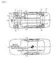
- Fig. 1 illustrates, as a first embodiment, a vehicle equipped with a braking control device of the present invention.
- Installed in a vehicle 14 are: a ground speed sensor 1 , which is a radar sensor or the like that detects relative speed with respect to a road surface; a brake unit 2 that controls braking force of each wheel, and which here is a hydraulic brake unit that controls pressure applied to hydraulic brake calipers; an electronic control unit 3 that conducts calculation processing on the basis of a signal from the sensor and controls, on the basis of the calculation result, an actuator and an actuator such as a brake unit and shock absorbers that can vary a damping coefficient; a steering angle sensor 4 that detects a steering angle; a stroke sensor 5 that detects, as a stroke, a depression amount of an accelerator pedal; wheel speed sensors 6, 7, 8 and 9 that detect wheel speeds of wheels; and brake calipers 10, 11, 12 and 13 that control the braking force.
- a ground speed sensor 1 which is a radar sensor or the like that detects relative speed with respect to
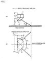
- Figs. 2 illustrate an exterior of the ground speed sensor 1. It should be noted that this is nothing more than an example of the embodiment and includes sensors that have the same function(s) even if they have other shapes and layouts.
- (a) is a view seen from a side surface
- (b) is a view seen from an upper surface. It is attached to a structural member 21 of the vehicle.
- a left antenna cover surface 22 slants only at ⁇ v (e.g., within the range of 30° to 60°) with respect to the road surface. It also slants only at ⁇ L (e.g., within the range of 30° to 60°) with respect to a vehicle front-rear central axis of the vehicle.
- the left antenna cover surface From the left antenna cover surface, it outputs a transmission wave while switching at a time division to a first frequency and a second frequency facing the road surface, and receives a reflection wave from the road surface.
- a right antenna cover surface 23 slants only at ⁇ R , and it outputs a transmission wave while switching at a time division to a third frequency and a fourth frequency facing the road surface, and receives a reflection wave from the road surface.
- the changing of the frequency of the transmission wave from a first antenna cover surface and the frequency of the transmission wave from a second antenna cover surface is for preventing interference between adjacently disposed first and second antennas (not illustrated) and for improving measurement precision.
- the directivity of the first and second antennas it is preferable for the directivity of the first and second antennas to be within ⁇ 1°. By making the directivity to be within ⁇ 1°, precision within ⁇ 2 km/h can be realized.
- Fig. 3 illustrates a processing flow that calculates a traveling direction speed vehicle speed V Z that is a front-rear direction speed of the vehicle in the ground speed sensor, a left-right direction speed V Y , and a measured angle of sideslip ⁇ m .
- step S301 Fourier analysis (FFT processing) is conducted for extracting the Doppler shift superposed on the reflection wave by the first frequency transmission wave (frequency f 1 ) transmitted from the right antenna.
- FFT processing is similarly conducted for extracting the Doppler shift superposed on the reflection wave by the second frequency transmission wave transmitted from the right antenna.
- step S303 a first signal strength peak (S R1 , f d1 ) revealed as the Doppler shift is extracted from the FFT processing result calculated in S301.
- step S303 an electric wave propagation distance R L is calculated from the extracted first signal strength peak S R1 and the second signal strength peak S R2 .
- R L c ⁇ ⁇ R1 - ⁇ R2 4 ⁇ ⁇ ⁇ ⁇ f
- c is light speed
- ⁇ f is the difference between the first frequency and the second frequency
- step S304 a measured ground speed V R of the right antenna is taken if the electric wave propagation distance R L is within a predetermined range.
- V R c ⁇ (f d1 + f d2 ) 2 ⁇ (f 1 + f 2 )
- Step S305 to step S308 are similarly a processing flow that measures the ground speed V L at the left antenna.
- step S305 Fourier analysis (FFT processing) is conducted for extracting the Doppler shift superposed on the reflection wave by the third frequency transmission wave (frequency f 3 ) transmitted from the left antenna.
- step S306 FFT processing is similarly conducted for extracting the Doppler shift superposed on the reflection wave by the fourth frequency transmission wave transmitted from the left antenna.
- a third signal strength peak (S R3 , f d3 ) revealed as the Doppler shift is extracted from the FFT processing result calculated in S305.
- step S307 an electric wave propagation distance R L is calculated from the extracted third signal strength peak S R3 and the fourth signal strength peak S R4 .
- R L c ⁇ ⁇ L3 - ⁇ L4 4 ⁇ ⁇ ⁇ ⁇ f
- c is light speed
- ⁇ f is the difference between the third frequency and the fourth frequency.
- step S308 a measured ground speed V L of the left antenna is taken if the electric wave propagation distance R L is within a predetermined range.
- V L c ⁇ (f d3 + f d4 ) 2 ⁇ (f 3 + f 4 )
- step S309 the traveling direction speed V Z of the vehicle is calculated from the ground speed V R and the ground speed V L .
- step S310 the left-right direction speed V Y of the vehicle is calculated.
- step S311 the measured angle of sideslip ⁇ m is calculated.
- ⁇ m Arc tan V Y V Z
- the traveling direction speed V Z of the vehicle the left-right direction speed V Y of the vehicle, and the measured angle of sideslip ⁇ m can be measured. Moreover, by time-differentiating these measured values, the yaw angle speed, traveling direction acceleration, and left-right direction acceleration can be calculated.
- Fig. 4 illustrates a hydraulic circuit of the hydraulic unit 2.
- Contained in the hydraulic unit 2 are an accumulator 401, a pump 402, a motor 403, a strainer 406, a spool valve 404, a pressure sensor 407, and four three-way valves 408, 409, 410 and 411.
- a stroke simulator 5 contained in a stroke simulator 5 are a cylinder 412, a tank 413, and a pressure sensor 414.
- the electronic control unit 3 is connected to the pressure sensor 407, the four three-way valves 408, 409, 410 and 411, the motor 403, and the pressure sensor 414.
- Fig. 5 illustrates a processing flow at the electronic control unit 3.
- a steering angle ⁇ is obtained on the basis of an output of the steering angle sensor.
- the traveling direction speed V Z calculated in the processing of Fig. 3 is obtained.
- a preset target angle of sideslip ⁇ T is obtained from the steering angle ⁇ and the traveling direction speed V z . It is possible to obtain the target angle of sideslip ⁇ T by calculating using approximation or searching from, for example, a map or correspondence chart of the target angle of sideslip ⁇ T corresponding to the steering angle ⁇ and the traveling direction speed V z .
- the measured angle of sideslip ⁇ m calculated in the processing of Fig. 3 is obtained.
- step S505 the amount of deviation between the target angle of sideslip ⁇ T and the measured angle of sideslip ⁇ m is processed by comparing whether it falls in a preset range of ⁇ ⁇ . Because it can be judged to be a neutral steer if it falls in the predetermined range, the determination becomes True in branch processing or comparative processing, the flow proceeds to step S506, and a corrected value ⁇ P of brake fluid pressure is set to zero. On the other hand, because it can be judged to be an over-steer or an under-steer if it falls outside of the predetermined range, the determination becomes False in the branch processing or comparative processing, and the flow proceeds to processing of step S506.
- step S506 the corrected value ⁇ P of brake fluid pressure is calculated from a current deviation amount ⁇ 0 and a previously calculated deviation amount ⁇ 1 .
- step S507 a pressure sensor value P SS within the stroke simulator 5 is obtained. Because the value of the pressure sensor value P SS increases in proportion to the force with which the driver depresses the pedal, it is the same as measuring the brake demand of the driver.
- step S508 target brake fluid pressures P TFR , P TFL , P TRR and P TRL of each wheel are set using the pressure sensor value P SS as a parameter.
- step S509 it is determined whether the corrected value ⁇ P of brake fluid pressure is zero.
- step S510 the positive/negative of the corrected value ⁇ P of brake fluid pressure is determined. If it is a positive value, the target brake fluid pressure P TFR of the front wheel right is increased only by the corrected value ⁇ P of brake fluid pressure and the processing is terminated. If it is a negative value, the target brake pressure P TFL of the front wheel left is increased only by the corrected value ⁇ P of brake fluid pressure and the processing is terminated.
- the corrected value ⁇ P of brake fluid pressure is a positive value
- effects that are the same as correcting the target brake fluid pressure P TFRO of the front wheel right can be obtained even if the target brake fluid pressure P TRR of the rear wheel right is increased only by the corrected value ⁇ P of brake fluid pressure.
- the same effects can be obtained even if the front wheel right target brake fluid pressure P TFR and the target brake fluid pressure P TRR of the rear wheel right are respectively corrected by ⁇ P/2.
- the corrected value ⁇ P of brake fluid pressure is a negative value
- the same effects can be obtained by similarly correcting the front wheel left and the rear wheel left or only the rear wheel left.
- the electronic control unit 3 electronically feedback-controls the four three-way valves 408, 409, 410 and 411 to realize the target brake fluid pressures P TFR , P TFL , P TRR and P TRL of each wheel.
- the amount of deviation between the target angle of sideslip ⁇ T and the measured angle of sideslip ⁇ m falls in the preset range of ⁇ . That is, it becomes possible to adjust the brake fluid pressure with the hydraulic unit so that it becomes as much as possible a neutral steer, and safer traveling of the vehicle is realized.
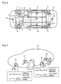
- Fig. 6 illustrates, as second embodiment, a vehicle equipped the vehicular travel control device of the present invention. Detailed description of elements that are the same as those in the first embodiment will be omitted.
- Fig. 6 installed in the vehicle 14 are four radar sensors 15, 16, 17 and 18, the hydraulic unit 2, the electronic control unit 3, the steering angle sensor 4, the stroke sensor 5, the wheel speed sensors 6, 7, 8 and 9, and the brake calipers 10, 11, 12 and 13.
- Fig. 7 is a view that illustrates the orientation at which the electric waves are emitted toward the road surface.
- the radar sensor 15 emits, in the traveling direction of the vehicle 14, a signal at an angle of 45 degrees to the road surface.
- the radar sensor 16 emits, in the reverse direction of the vehicle 14, a signal at an angle of 45 degrees.
- the radar sensor 17 emits, in the right direction of the vehicle 14, a signal at an angle of 45 degrees.
- the radar sensor 18 emits, in the left direction of the vehicle 14, a signal at an angle of 45 degrees.
- Each of the radar sensors measures the distance between the sensor and the road surface and the relative speed between the vehicle and the road surface.
- Fig. 8 is a functional block diagram of the radar sensors.
- the radar sensors comprise a signal processor 801, a voltage control carrier oscillator 802, a voltage control modulation oscillator 803, digital/analog (D/A) converters 804 and 805, a transmission mixer 806, a reception mixer 809, a transmitting antenna 807, a receiving antenna 808, a band-pass filter 810, and an analog/digital (A/D) converter 811.
- a carrier frequency f C (e.g., 76.5 GHz and 76.6 GHz) is generated by the voltage control carrier oscillator 802.
- the carrier frequency f C can alter the frequency by an output voltage of the D/A converter 805.
- a modulated frequency f M that is generated from the voltage control modulation oscillator 803 can also alter the frequency by an output voltage of the D/A converter 804.
- the generated modulated frequency f M and the carrier frequency f c are mixed at the transmission mixer 806 and transmitted to the road surface from the transmitting antenna 807.
- the reflection wave from the road surface is received by the receiving antenna 808 and downmixed by the reception mixer 809.
- a predetermined band signal is incorporated in the signal processor 801 by the band-pass filter 810 using the A/D converter 811. Fourier conversion is conducted at the signal processor 801. By analyzing the spectral data after Fourier conversion, the ground speed of the vehicle 14 equipped with the radar sensors is understood.
- the carrier frequency f C is switched at a time division into two of a first signal frequency and a second signal frequency by the voltage control carrier oscillator 802.
- Fourier conversion processing is conducted with respect to the reflection signals, and a phase difference ⁇ is detected from the reflection signal strength of the spectral peak of the first signal frequency and the reflection signal strength of the spectral peak of the second signal frequency.
- the phase difference ⁇ is proportional to the distance between the road surface and the radar sensors.
- Fig. 9 is a diagram illustrating the relationship between the on-duty and period of an output pulse signal from the signal processor 801.
- the frequency (period) is made proportionate to the phase difference ⁇ generated by the difference in the two carrier frequencies fc. That is, it is proportionate to the distance between the road surface and the radar sensors, and when the distance is long, the frequency is lowered (the period is lengthened), and when the distance is short, the frequency is raised (the period is shortened).
- the measured distance between the road surface and the radar sensors can be converted to the period of the output pulse signal and communicated from the radar sensors to the electronic control unit.
- an on-duty ratio W ON is made proportionate to a Doppler shift frequency f D . That is, when the speed is forward, the on-duty ratio is 50% or greater, and the on-duty ratio increases as the speed increases. When the speed is reverse, the on-duty ratio is less than 50%, and the on-duty ratio becomes smaller as the speed increases.
- the relative speed (ground speed) between the road surface and the radar sensors can be converted to the on-duty of the output pulse signal and communicated from the radar sensors to the electronic control unit. Information of the relative speed and distance can be superposed on the output pulse signals from the radar sensors by this method and transmitted to the electronic control sensor. Of course, it may also be transmitted by a traditional serial signal.
- Fig. 10 illustrates the physical quantities calculated inside the electronic control unit from the four radar sensors.
- the forward speed V X the left-right direction speed V Y , the vertical speed w, the angle of sideslip ⁇ , the pitch angle ⁇ , and the roll angle ⁇ are calculated.
- the forward speed V X is calculated by equation 12. (Equation 12)
- V X v 15 sin( ⁇ + ⁇ ) - v 16 sin( ⁇ - ⁇ ) 2
- V 15 is relative speed information of the radar sensor
- V 16 is relative speed information of the radar sensor 16
- ⁇ is the mounting angle between the radar sensors and the road surface (e.g., 45 degrees).
- V Y ⁇ 17 sin ( ⁇ + ⁇ ) - ⁇ 18 sin ( ⁇ - ⁇ ) 2
- V 17 is relative speed information of the radar sensor 17
- V 18 is relative speed information of the radar sensor 18.
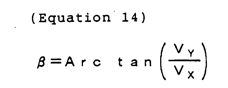
- the angle of sideslip ⁇ is calculated by equation 14.
- R 15 to R 18 are distance information of the radar sensor 15 to the radar sensor 18.
- the pitch angle ⁇ is calculated by equation 16.
- L VEHICLE is the length of the vehicle.
- roll angle ⁇ is calculated by equation 17.
- Fig. 11 illustrates, as a third embodiment, a vehicle equipped with the travel control device of the present invention.
- Installed in the vehicle 14 are three radar sensors 16, 17 and 18, the hydraulic unit 2, the electronic control unit 3, the steering angle sensor 4, the stroke sensor 5, the wheel speed sensors 6, 7, 8 and 9, and the brake calipers 10, 11, 12 and 13.
- the forward speed V X , the left-right direction speed V y , the vertical speed w, the angle of sideslip ⁇ , the pitch angle ⁇ , and the roll angle ⁇ can be calculated even by using the three radar sensors 16, 17 and 18.
- the forward speed V X is calculated by equation 12.
- V X - v 16 sin ( ⁇ - ⁇ )
- V 16 is relative speed information of the radar sensor 16
- ⁇ is the mounting angle between the radar sensors and the road surface (e.g., 45 degrees).
- V Y v 17 sin( ⁇ + ⁇ ) - v 18 sin( ⁇ - ⁇ ) 2
- V 17 is relative speed information of the radar sensor 17
- V 18 is relative speed information of the radar sensor 18.
- the angle of sideslip ⁇ is calculated by equation 20.
- R 16 to R 18 are distance information of the radar sensor 15 to the radar sensor 18.
- the pitch angle ⁇ is calculated by equation 16.
- L VEHICLE is the length of the vehicle.
- roll angle ⁇ is calculated by equation 17.
- six physical quantities-the forward speed, the left-right direction speed, the vertical speed, the angle of sideslip, the pitch angle, and the roll angle-can be calculated by using three or four radar sensors. Also, three physical quantities-the forward speed, the left-right speed, and the angle of sideslip-can be calculated by using two radar sensors.
- the invention it becomes possible to obtain six physical quantities-the forward speed, the left-right direction speed, the vertical speed, the angle of sideslip, the pitch angle, and the roll angle-necessary for the momentum of a vehicle with a few number of radar sensors.
- a vehicle in which braking distance at the time of braking is more shortened and vehicle behavior is more stable can be provided.
Landscapes
- Engineering & Computer Science (AREA)
- Radar, Positioning & Navigation (AREA)
- Remote Sensing (AREA)
- Mechanical Engineering (AREA)
- Computer Networks & Wireless Communication (AREA)
- General Physics & Mathematics (AREA)
- Physics & Mathematics (AREA)
- Transportation (AREA)
- Automation & Control Theory (AREA)
- Regulating Braking Force (AREA)
- Vehicle Body Suspensions (AREA)
- Control Of Driving Devices And Active Controlling Of Vehicle (AREA)
- Radar Systems Or Details Thereof (AREA)
Abstract
The invention relates to a control device, wherein six physical
quantities-forward-reverse speed, left-right speed, vertical speed,
pitch angle, roll angle, and angle of sideslip-representing vehicular
movement and to control the braking force of each wheel and/or the
damping coefficient of each suspension shock absorber in order to
further shorten braking distance particularly at the time of braking and
to prevent spin at that time are measured or calculated. In this case,
it is necessary to furnish wheel speed and steering angle sensors
(4;6...9;15...18) to measure speed and angle directly. In the present
invention, four radar sensors (15...18) are used in order to directly
measure the forward-reverse Speed and the left-right speed on the basis
of at least one of a phase difference between an emission signal
transmitted toward a road surface from the radar sensors (15...18) and a
reflection signal reflected from the road surface and received by the
radar sensors (15...18) and a Doppler shift frequency superposed on the
reflection signal. Also, the vertical speed, the pitch angle, the roll
angle, and the angle of sideslip are indirectly measured from the output
of the radar sensors (15...18). By using three or four radar sensors,
six physical quantities-the forward speed, the left-right direction
speed, the vertical speed, the angle of sideslip, the pitch angle, and
the roll angle-can be measured. Also, by using two radar sensors, three
physical quantites-the forward speed, the left-right speed, and the
angle of sideslip-can be measured.
Description
- The present invention relates to a vehicular travel control device using radar sensors.
- An electric control device that is equipped with six different kinds of sensors-speed sensors, forward-reverse acceleration sensor, left-right acceleration sensor, vertical acceleration sensor, clearance sensor, and yaw rate sensor-for a total of sixteen sensors, calculates six physical quantities-forward-reverse speed, left-right speed, vertical speed, pitch angle, roll angle, and yaw angle-representing vehicular movement, and conducts control of shock absorbers is disclosed in JP-A-2001-47832.
- In a vehicular control device, it is necessary to measure or calculate six physical quantities-forward-reverse speed, left-right speed, vertical speed, pitch angle, roll angle, and angle of sideslip-representing vehicular movement and to control the braking force of each wheel and/or the damping coefficient of each suspension shock absorber in order to further shorten braking distance particularly at the time of braking and to prevent spin at that time. However, there has been the problem that, in the prior art, speed and angle must be directly measured using many different kinds of sensors in order to obtain these physical quantities, and the burdens of cost, maintenance, adjustment, and control have been great.
- In order to solve the above-described problem, the present invention is characterized in that forward-reverse speed, left-right speed, and/or vertical distance from a road surface are directly measured by radar sensors, and is further characterized in that vertical speed, pitch angle, roll angle, and/or angle of sideslip are indirectly measured or calculated from outputs of the radar sensors.
-
- Fig. 1 illustrates a vehicle of a first embodiment equipped with a vehicular travel control device.
- Figs. 2 illustrates an exterior of a radar sensor. (a) side surface, (b) upper surface.
- Fig. 3 illustrates a processing flow of the radar sensors.
- Fig. 4 illustrates a hydraulic circuit of a hydraulic unit.
- Fig. 5 illustrates a processing flow of an electronic control unit.
- Fig. 6 illustrates a vehicle of a second embodiment equipped with the vehicular travel control device.
- Fig. 7 illustrates a reflection signal and emission direction of a transmission signal of the radar sensor.
- Fig. 8 is a functional block diagram of the radar sensors.
- Fig. 9 illustrates the relationship between on-duty and a frequency of an output pulse signal.
- Fig. 10 illustrates physical quantities of vehicular movement processed by the electronic control unit.
- Fig. 11 illustrates a vehicle of a third embodiment equipped with the vehicular travel control device.
-
- In the present invention, radar sensors are used to directly measure forward-reverse speed, left-right speed, and/or vertical distance from a road surface. Also, vertical speed, pitch angle, roll angle, and/or angle of sideslip are indirectly measured from outputs of the radar sensors.
- In the present invention, there are disposed plural radar sensors and an electronic control unit containing a computer, with a Doppler shift frequency superposed on a reflection signal of a signal emitted toward a road surface from the radar sensors being detected by each radar sensor, and the forward-reverse speed and/or the left-right speed being calculated and communicated to the electronic control unit. The vertical speed, pitch angle, roll angle, and/or angle of sideslip, which are physical quantities of vehicular movement, can be calculated on the basis of the detection result (speed, etc.) received at the electronic control unit.
- The radar sensors of the present invention may include an emission section having a function of emitting a signal whose frequency can be changed, a reflection signal receiving section having a reflection signal receiving function, a phase difference detection section having a phase difference detecting function, a Doppler shift frequency detection section having a Doppler shift frequency detecting function, and/or an output pulse signal modulation section having an output pulse signal modulating function. The radar sensors or a peripheral section including the radar sensors, the phase difference detection section, the Doppler frequency detection section, and/or the modulation section detect, with the phase difference detection section, the phase difference of each reflection signal of two signals whose frequencies are different and that are emitted from the emission section toward a road surface, and/or vary one of a frequency or on-duty ratio of the output pulse signal by the output pulse signal modulation section.
- In the present invention, there are included plural radar sensors, a steering angle sensor, a brake unit that varies braking force of each wheel, and/or an electronic control unit containing a computer, with a Doppler shift frequency superposed on a reflection signal of a signal emitted toward a road surface being detected by each radar sensor and/or the braking force of each wheel being varied on the basis of the detection result. The detection result detected by the sensors includes the function of being transmitted to the electronic control unit.
- Also, as for the detection result, a measured angle of sideslip and a forward-reverse speed (ground speed) can be calculated in the electronic control unit on the basis of the detection result. Moreover, the braking force of each wheel can be varied so that the measured angle of sideslip follows a target angle of sideslip set from the steering angle and the ground speed.
- Moreover, there can be included wheel speed sensors disposed in correspondence to each wheel, with the Doppler shift frequency superposed on the reflection signal of the emission signal emitted toward the road surface being detected by each radar sensor, and/or the braking force of each wheel being varied in the electronic control unit so that each wheel speed sensor measured value follows each target wheel speed set on the basis of the Doppler shift frequency.
- Moreover, there can be included damping coefficient varying shock absorbers corresponding to each wheel, with the phase difference between the reflection signal and the signal emitted toward the road surface and the Doppler shift frequency superposed on the reflection signal being detected by each radar sensor. The damping coefficient of each shock absorber or the braking force of each wheel may be varied on the basis of the phase difference and the Doppler shift frequency.
- Of the plural radar sensors and the electronic control unit containing the computer, at least one of the radar sensors and the electronic control unit are connected via at least two electrical wires (twist pair) and communicate with a pulse signal.
- The present invention is also a vehicle equipped with the vehicular travel control device.
- Fig. 1 illustrates, as a first embodiment, a vehicle equipped with a braking control device of the present invention. Installed in a vehicle 14 are: a ground speed sensor 1 , which is a radar sensor or the like that detects relative speed with respect to a road surface; a brake unit 2 that controls braking force of each wheel, and which here is a hydraulic brake unit that controls pressure applied to hydraulic brake calipers; an electronic control unit 3 that conducts calculation processing on the basis of a signal from the sensor and controls, on the basis of the calculation result, an actuator and an actuator such as a brake unit and shock absorbers that can vary a damping coefficient; a steering angle sensor 4 that detects a steering angle; a stroke sensor 5 that detects, as a stroke, a depression amount of an accelerator pedal; wheel speed sensors 6, 7, 8 and 9 that detect wheel speeds of wheels; and brake calipers 10, 11, 12 and 13 that control the braking force.
- Figs. 2 illustrate an exterior of the ground speed sensor 1. It should be noted that this is nothing more than an example of the embodiment and includes sensors that have the same function(s) even if they have other shapes and layouts. (a) is a view seen from a side surface, and (b) is a view seen from an upper surface. It is attached to a structural member 21 of the vehicle. A left antenna cover surface 22 slants only at v (e.g., within the range of 30° to 60°) with respect to the road surface. It also slants only at L (e.g., within the range of 30° to 60°) with respect to a vehicle front-rear central axis of the vehicle. From the left antenna cover surface, it outputs a transmission wave while switching at a time division to a first frequency and a second frequency facing the road surface, and receives a reflection wave from the road surface. Similarly, a right antenna cover surface 23 slants only at R, and it outputs a transmission wave while switching at a time division to a third frequency and a fourth frequency facing the road surface, and receives a reflection wave from the road surface. Here, the changing of the frequency of the transmission wave from a first antenna cover surface and the frequency of the transmission wave from a second antenna cover surface is for preventing interference between adjacently disposed first and second antennas (not illustrated) and for improving measurement precision. Also, it is preferable for the directivity of the first and second antennas to be within ± 1°. By making the directivity to be within ± 1°, precision within ± 2 km/h can be realized.
- Fig. 3 illustrates a processing flow that calculates a traveling direction speed vehicle speed VZ that is a front-rear direction speed of the vehicle in the ground speed sensor, a left-right direction speed VY, and a measured angle of sideslip βm. In step S301, Fourier analysis (FFT processing) is conducted for extracting the Doppler shift superposed on the reflection wave by the first frequency transmission wave (frequency f1) transmitted from the right antenna. In step S302, FFT processing is similarly conducted for extracting the Doppler shift superposed on the reflection wave by the second frequency transmission wave transmitted from the right antenna. In step S303, a first signal strength peak (SR1, fd1) revealed as the Doppler shift is extracted from the FFT processing result calculated in S301.
- Also, a second signal strength peak (SR2, fd2) revealed as the Doppler shift is extracted from the FFT processing result calculated in S302.
- In step S303, an electric wave propagation distance RL is calculated from the extracted first signal strength peak SR1 and the second signal strength peak SR2.
- Here, c is light speed, and Δf is the difference between the first frequency and the second frequency.
- In step S304, a measured ground speed VR of the right antenna is taken if the electric wave propagation distance RL is within a predetermined range.
- Step S305 to step S308 are similarly a processing flow that measures the ground speed VL at the left antenna. In step S305, Fourier analysis (FFT processing) is conducted for extracting the Doppler shift superposed on the reflection wave by the third frequency transmission wave (frequency f3) transmitted from the left antenna. In step S306, FFT processing is similarly conducted for extracting the Doppler shift superposed on the reflection wave by the fourth frequency transmission wave transmitted from the left antenna. In step S307, a third signal strength peak (SR3, fd3) revealed as the Doppler shift is extracted from the FFT processing result calculated in S305.
- Similarly, a fourth signal strength peak (SR4, fd4) revealed as the Doppler shift is extracted from the FFT processing result calculated in S306.
- In step S307, an electric wave propagation distance RL is calculated from the extracted third signal strength peak SR3 and the fourth signal strength peak SR4.
- Here, c is light speed, and Δf is the difference between the third frequency and the fourth frequency.
- In step S308, a measured ground speed VL of the left antenna is taken if the electric wave propagation distance RL is within a predetermined range.
- In step S309, the traveling direction speed VZ of the vehicle is calculated from the ground speed VR and the ground speed VL.

- In step S310, the left-right direction speed VY of the vehicle is calculated.

- Moreover, in step S311, the measured angle of sideslip βm is calculated.
- By this series of processing, the traveling direction speed VZ of the vehicle, the left-right direction speed VY of the vehicle, and the measured angle of sideslip βm can be measured. Moreover, by time-differentiating these measured values, the yaw angle speed, traveling direction acceleration, and left-right direction acceleration can be calculated.
- Fig. 4 illustrates a hydraulic circuit of the hydraulic unit 2. Contained in the hydraulic unit 2 are an accumulator 401, a pump 402, a motor 403, a strainer 406, a spool valve 404, a pressure sensor 407, and four three-way valves 408, 409, 410 and 411. Also, contained in a stroke simulator 5 are a cylinder 412, a tank 413, and a pressure sensor 414. The electronic control unit 3 is connected to the pressure sensor 407, the four three-way valves 408, 409, 410 and 411, the motor 403, and the pressure sensor 414.
- Fig. 5 illustrates a processing flow at the electronic control unit 3. In step S501, a steering angle is obtained on the basis of an output of the steering angle sensor. In step S502, the traveling direction speed VZ calculated in the processing of Fig. 3 is obtained. In step S503, a preset target angle of sideslip βT is obtained from the steering angle and the traveling direction speed Vz. It is possible to obtain the target angle of sideslip βT by calculating using approximation or searching from, for example, a map or correspondence chart of the target angle of sideslip βT corresponding to the steering angle and the traveling direction speed Vz. In step S504, the measured angle of sideslip βm calculated in the processing of Fig. 3 is obtained. In step S505, the amount of deviation between the target angle of sideslip βT and the measured angle of sideslip βm is processed by comparing whether it falls in a preset range of ± Δβ. Because it can be judged to be a neutral steer if it falls in the predetermined range, the determination becomes True in branch processing or comparative processing, the flow proceeds to step S506, and a corrected value ΔP of brake fluid pressure is set to zero. On the other hand, because it can be judged to be an over-steer or an under-steer if it falls outside of the predetermined range, the determination becomes False in the branch processing or comparative processing, and the flow proceeds to processing of step S506. In step S506, the corrected value ΔP of brake fluid pressure is calculated from a current deviation amount Δβ0 and a previously calculated deviation amount Δβ1. In step S507, a pressure sensor value PSS within the stroke simulator 5 is obtained. Because the value of the pressure sensor value PSS increases in proportion to the force with which the driver depresses the pedal, it is the same as measuring the brake demand of the driver. In step S508, target brake fluid pressures PTFR, PTFL, PTRR and PTRL of each wheel are set using the pressure sensor value PSS as a parameter. In step S509, it is determined whether the corrected value ΔP of brake fluid pressure is zero. If it is zero, the determination becomes True in the branch processing or comparative processing, and the processing is concluded. If it is not zero, the determination becomes False, the processing proceeds to step S510, and in step S510 the positive/negative of the corrected value ΔP of brake fluid pressure is determined. If it is a positive value, the target brake fluid pressure PTFR of the front wheel right is increased only by the corrected value ΔP of brake fluid pressure and the processing is terminated. If it is a negative value, the target brake pressure PTFL of the front wheel left is increased only by the corrected value ΔP of brake fluid pressure and the processing is terminated. Of course, when the corrected value ΔP of brake fluid pressure is a positive value, effects that are the same as correcting the target brake fluid pressure PTFRO of the front wheel right can be obtained even if the target brake fluid pressure PTRR of the rear wheel right is increased only by the corrected value ΔP of brake fluid pressure. Moreover, the same effects can be obtained even if the front wheel right target brake fluid pressure PTFR and the target brake fluid pressure PTRR of the rear wheel right are respectively corrected by ΔP/2. In a case where the corrected value ΔP of brake fluid pressure is a negative value, the same effects can be obtained by similarly correcting the front wheel left and the rear wheel left or only the rear wheel left.
- The electronic control unit 3 electronically feedback-controls the four three-way valves 408, 409, 410 and 411 to realize the target brake fluid pressures PTFR, PTFL, PTRR and PTRL of each wheel. Thus, the amount of deviation between the target angle of sideslip βT and the measured angle of sideslip βm falls in the preset range of ±Δβ. That is, it becomes possible to adjust the brake fluid pressure with the hydraulic unit so that it becomes as much as possible a neutral steer, and safer traveling of the vehicle is realized.
- Fig. 6 illustrates, as second embodiment, a vehicle equipped the vehicular travel control device of the present invention. Detailed description of elements that are the same as those in the first embodiment will be omitted. In Fig. 6, installed in the vehicle 14 are four radar sensors 15, 16, 17 and 18, the hydraulic unit 2, the electronic control unit 3, the steering angle sensor 4, the stroke sensor 5, the wheel speed sensors 6, 7, 8 and 9, and the brake calipers 10, 11, 12 and 13.
- Fig. 7 is a view that illustrates the orientation at which the electric waves are emitted toward the road surface. The radar sensor 15 emits, in the traveling direction of the vehicle 14, a signal at an angle of 45 degrees to the road surface. The radar sensor 16 emits, in the reverse direction of the vehicle 14, a signal at an angle of 45 degrees. The radar sensor 17 emits, in the right direction of the vehicle 14, a signal at an angle of 45 degrees. The radar sensor 18 emits, in the left direction of the vehicle 14, a signal at an angle of 45 degrees. Each of the radar sensors measures the distance between the sensor and the road surface and the relative speed between the vehicle and the road surface.
- Fig. 8 is a functional block diagram of the radar sensors. The radar sensors comprise a signal processor 801, a voltage control carrier oscillator 802, a voltage control modulation oscillator 803, digital/analog (D/A) converters 804 and 805, a transmission mixer 806, a reception mixer 809, a transmitting antenna 807, a receiving antenna 808, a band-pass filter 810, and an analog/digital (A/D) converter 811. A carrier frequency fC (e.g., 76.5 GHz and 76.6 GHz) is generated by the voltage control carrier oscillator 802. The carrier frequency fC can alter the frequency by an output voltage of the D/A converter 805. Also, a modulated frequency fM that is generated from the voltage control modulation oscillator 803 can also alter the frequency by an output voltage of the D/A converter 804. The generated modulated frequency fM and the carrier frequency fc are mixed at the transmission mixer 806 and transmitted to the road surface from the transmitting antenna 807. The reflection wave from the road surface is received by the receiving antenna 808 and downmixed by the reception mixer 809. Moreover, a predetermined band signal is incorporated in the signal processor 801 by the band-pass filter 810 using the A/D converter 811. Fourier conversion is conducted at the signal processor 801. By analyzing the spectral data after Fourier conversion, the ground speed of the vehicle 14 equipped with the radar sensors is understood. In a case where the ground speed is zero, there is a spectral peak in the modulated frequency fM. In a case where there is a ground speed, a spectral peak appears in the frequency fM + fD. The graph of Fig. 8 illustrates an example of a case where a spectral peak appears in the frequency fM + fD.
- The carrier frequency fC is switched at a time division into two of a first signal frequency and a second signal frequency by the voltage control carrier oscillator 802. In each frequency, Fourier conversion processing is conducted with respect to the reflection signals, and a phase difference ΔΨ is detected from the reflection signal strength of the spectral peak of the first signal frequency and the reflection signal strength of the spectral peak of the second signal frequency. The phase difference Δψ is proportional to the distance between the road surface and the radar sensors.
- Fig. 9 is a diagram illustrating the relationship between the on-duty and period of an output pulse signal from the signal processor 801. First, the frequency (period) is made proportionate to the phase difference ΔΨ generated by the difference in the two carrier frequencies fc. That is, it is proportionate to the distance between the road surface and the radar sensors, and when the distance is long, the frequency is lowered (the period is lengthened), and when the distance is short, the frequency is raised (the period is shortened). Thus, the measured distance between the road surface and the radar sensors can be converted to the period of the output pulse signal and communicated from the radar sensors to the electronic control unit.
- Next, an on-duty ratio WON is made proportionate to a Doppler shift frequency fD. That is, when the speed is forward, the on-duty ratio is 50% or greater, and the on-duty ratio increases as the speed increases. When the speed is reverse, the on-duty ratio is less than 50%, and the on-duty ratio becomes smaller as the speed increases. Thus, the relative speed (ground speed) between the road surface and the radar sensors can be converted to the on-duty of the output pulse signal and communicated from the radar sensors to the electronic control unit. Information of the relative speed and distance can be superposed on the output pulse signals from the radar sensors by this method and transmitted to the electronic control sensor. Of course, it may also be transmitted by a traditional serial signal.
- Fig. 10 illustrates the physical quantities calculated inside the electronic control unit from the four radar sensors. Inside the electronic control unit, the forward speed VX, the left-right direction speed VY, the vertical speed w, the angle of sideslip β, the pitch angle , and the roll angle are calculated. First, the forward speed VX is calculated by equation 12.
- Here, V15 is relative speed information of the radar sensor 15, V16 is relative speed information of the radar sensor 16, and α is the mounting angle between the radar sensors and the road surface (e.g., 45 degrees). Next, the left-right direction speed VY is calculated by equation 13.
- Here, V17 is relative speed information of the radar sensor 17, and V18 is relative speed information of the radar sensor 18. Next, the angle of sideslip β is calculated by equation 14.
- Next, the vertical distance between each radar sensor and the road surface is calculated by equations 15.
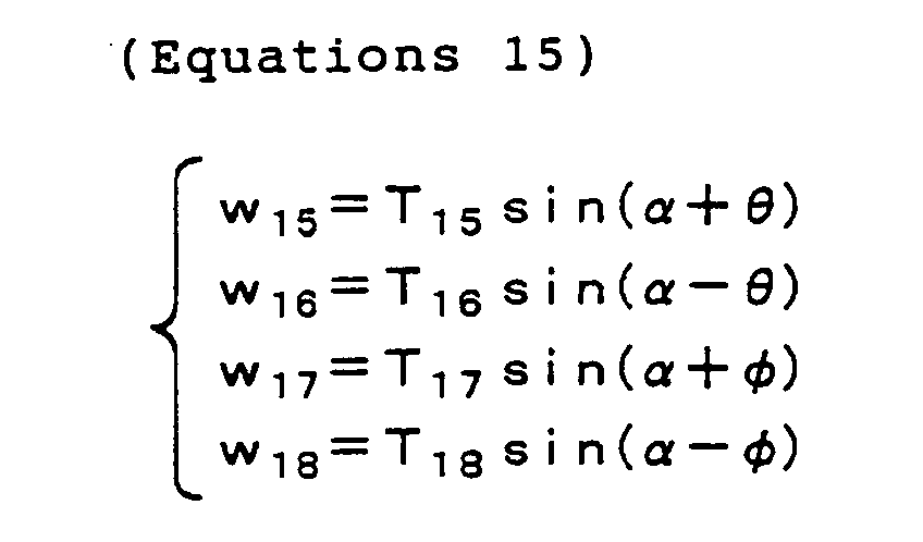
- Here, R15 to R18 are distance information of the radar sensor 15 to the radar sensor 18. Next, the pitch angle is calculated by equation 16.

- Here, LVEHICLE is the length of the vehicle. Lastly, the roll angle is calculated by equation 17.

- By repeatedly calculating the calculations of equation 12 to equation 17 per predetermined period, it becomes possible to calculate the forward speed VX, the left-right direction speed VY, the vertical speed w, the angle of sideslip β, the pitch angle , and the roll angle . At this time, the initial values of the pitch angle and the roll angle are respectively set to zero, and calculation becomes simple when the pitch angle and the roll angle of the previous period are used per period.
- Fig. 11 illustrates, as a third embodiment, a vehicle equipped with the travel control device of the present invention. Installed in the vehicle 14 are three radar sensors 16, 17 and 18, the hydraulic unit 2, the electronic control unit 3, the steering angle sensor 4, the stroke sensor 5, the wheel speed sensors 6, 7, 8 and 9, and the brake calipers 10, 11, 12 and 13. The forward speed VX, the left-right direction speed Vy, the vertical speed w, the angle of sideslip β, the pitch angle , and the roll angle can be calculated even by using the three radar sensors 16, 17 and 18. First, the forward speed VX is calculated by equation 12.
- Here, V16 is relative speed information of the radar sensor 16, and α is the mounting angle between the radar sensors and the road surface (e.g., 45 degrees). Next, the left-right direction speed VY is calculated by equation 19.
- Here, V17 is relative speed information of the radar sensor 17, and V18 is relative speed information of the radar sensor 18. Next, the angle of sideslip β is calculated by equation 20.

- Next, the vertical distance between each radar sensor and the road surface is calculated by equations 15.

- Here, R16 to R18 are distance information of the radar sensor 15 to the radar sensor 18. Next, the pitch angle is calculated by equation 16.
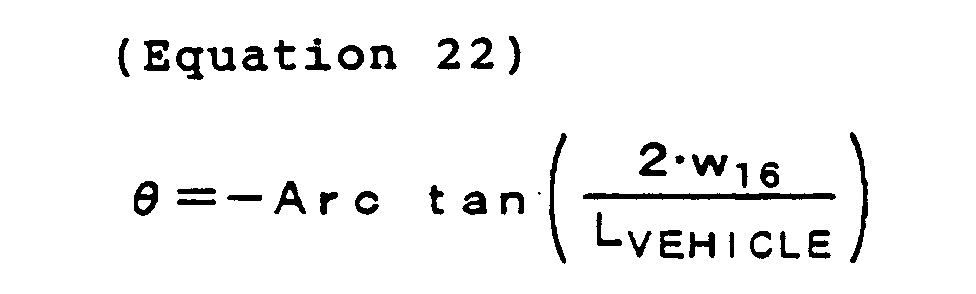
- Here, LVEHICLE is the length of the vehicle. Lastly, the roll angle is calculated by equation 17.

- By repeatedly calculating the calculations of equation 18 to equation 23 per predetermined period, it becomes possible to calculate the forward speed VX, the left-right direction speed VY, the vertical speed w, the angle of sideslip β, the pitch angle , and the roll angle . At this time, the initial values of the pitch angle and the roll angle are respectively set to zero, and calculation becomes simple when the pitch angle and the roll angle of the previous period are used per period.
- According to the invention, six physical quantities-the forward speed, the left-right direction speed, the vertical speed, the angle of sideslip, the pitch angle, and the roll angle-can be calculated by using three or four radar sensors. Also, three physical quantities-the forward speed, the left-right speed, and the angle of sideslip-can be calculated by using two radar sensors.
- According to the invention, it becomes possible to obtain six physical quantities-the forward speed, the left-right direction speed, the vertical speed, the angle of sideslip, the pitch angle, and the roll angle-necessary for the momentum of a vehicle with a few number of radar sensors.
- Also, because the information of relative speed and distance is superposed on the on-duty and period of the pulse signal, communication between the radar sensors and the electronic control unit in which the adverse effect of noise is reduced becomes possible.
- Moreover, a vehicle in which braking distance at the time of braking is more shortened and vehicle behavior is more stable can be provided.
Claims (8)
- A vehicular travel control device including at least a control unit (3) that conducts calculation processing on the basis of signals from plural radar sensors (15 ... 18), the vehicular travel control device calculating physical quantities of vehicular movement with the control unit (3) on the basis of at least one of a phase difference between an emission signal transmitted toward a road surface from the radar sensors (15 .. 18) and a reflection signal reflected from the road surface and received by the radar sensors (15 ... 18) and a Doppler shift frequency superposed on the reflection signal.
- A vehicular travel control device including at least: radar sensors (15 ... 18) that emit an emission signal onto a road surface and receive a reflection signal resulting from the emission signal being reflected from the road surface; a steering angle sensor (4) that detects a steering angle; a brake unit (2) that controls a braking force of wheels; and a control unit (3) that inputs a signal from the radar sensors (15 ... 18) or the steering angle sensor (4), processes the inputted signal, and outputs the processed signal to the brake unit (2); wherein a Doppler shift frequency superposed on the reflection signal is detected and the braking force of the wheels is controlled on the basis of the detected Doppler frequency.
- The vehicular travel control device of claim 2, wherein a measured angle of sideslip and a ground speed are calculated on the basis of the Doppler shift frequency, and the braking force of the wheels is controlled so that the measured angle of sideslip follows a target angle of sideslip set from the ground speed and the steering angle detected by the steering angle sensor (4).
- The vehicular travel control device of claim 3, further including wheel speed sensors (6 ... 9) disposed in correspondence to the wheels, wherein the braking force of the wheels is controlled so that a measured wheel speed value detected by the wheel speed sensors (6 ... 9) follows a target wheel speed set on the basis of the Doppler shift frequency.
- The vehicular travel control device of claim 4, further including shock absorbers that vary a damping coefficient corresponding to the wheels, wherein the damping coefficient of the shock absorbers or the braking force of the wheels is controlled on the basis of the phase difference between the emission signal and the reflection signal and the Doppler shift frequency superposed on the reflection signal.
- The vehicular travel control device of claim 2, wherein the radar sensors (15 ... 18) and the control unit (3) are connected by at least two electrical wires and communicate with a pulse signal between the radar sensors (15 ... 18) and the control unit (3).
- A vehicle that includes the vehicular travel control device of claim 2 including the control unit (3).
- A radar sensor that emits an emission signal onto a road surface and receives a reflection signal resulting from the emission signal being reflected from the road surface, wherein at least one of a frequency or on-duty ratio of an output pulse signal is varied on the basis of a phase difference between plural reflection signals of different frequencies and the other is varied on the basis of a Doppler shift frequency superposed on the reflection signal.
Applications Claiming Priority (2)
| Application Number | Priority Date | Filing Date | Title |
|---|---|---|---|
| JP2003003834 | 2003-01-10 | ||
| JP2003003834A JP2004216954A (en) | 2003-01-10 | 2003-01-10 | Vehicle travel control device |
Publications (1)
| Publication Number | Publication Date |
|---|---|
| EP1437276A1 true EP1437276A1 (en) | 2004-07-14 |
Family
ID=32501236
Family Applications (1)
| Application Number | Title | Priority Date | Filing Date |
|---|---|---|---|
| EP20030008049 Withdrawn EP1437276A1 (en) | 2003-01-10 | 2003-04-14 | Vehicular travel control device |
Country Status (3)
| Country | Link |
|---|---|
| US (1) | US7136736B2 (en) |
| EP (1) | EP1437276A1 (en) |
| JP (1) | JP2004216954A (en) |
Cited By (7)
| Publication number | Priority date | Publication date | Assignee | Title |
|---|---|---|---|---|
| WO2007101796A1 (en) * | 2006-03-06 | 2007-09-13 | Robert Bosch Gmbh | System for regulating the position of the chassis of a motor vehicle |
| GB2441420A (en) * | 2006-08-30 | 2008-03-05 | Ford Global Tech Llc | A Method and System for Controlling a Motor Vehicle |
| CN102256817A (en) * | 2008-12-19 | 2011-11-23 | 法国欧陆汽车公司 | Method for locating the longitudinal position of the wheels of a vehicle |
| WO2016032905A1 (en) * | 2014-08-29 | 2016-03-03 | Viasat, Inc. | Interference mitigation for a velocity sensing controller |
| CN109507672A (en) * | 2018-10-23 | 2019-03-22 | 福瑞泰克智能系统有限公司 | A kind of vehicle radar system and vehicle of omnibearing visual angle |
| CN111284287A (en) * | 2018-12-06 | 2020-06-16 | 现代自动车株式会社 | Active suspension control unit and method |
| CN114608849A (en) * | 2020-12-08 | 2022-06-10 | 美智纵横科技有限责任公司 | Sweeper state detection method and device, electronic equipment and storage medium |
Families Citing this family (54)
| Publication number | Priority date | Publication date | Assignee | Title |
|---|---|---|---|---|
| US8121770B2 (en) * | 2001-07-31 | 2012-02-21 | Kelsey-Hayes Company | Boundary adaptation scheme for spool valve pressure control |
| JP4337638B2 (en) * | 2003-06-30 | 2009-09-30 | 株式会社日立製作所 | Ground speed measuring device |
| JP4314250B2 (en) * | 2006-05-23 | 2009-08-12 | トヨタ自動車株式会社 | Road surface determination device for vehicles |
| JP4713408B2 (en) * | 2006-06-07 | 2011-06-29 | トヨタ自動車株式会社 | Vehicle control device |
| US7934092B2 (en) * | 2006-07-10 | 2011-04-26 | Silverbrook Research Pty Ltd | Electronic device having improved security |
| JP4977443B2 (en) * | 2006-10-31 | 2012-07-18 | 日立オートモティブシステムズ株式会社 | Radar apparatus and radar detection method |
| JP4957272B2 (en) * | 2007-01-31 | 2012-06-20 | トヨタ自動車株式会社 | Vehicle speed information estimation device |
| DE102008038615A1 (en) * | 2007-09-18 | 2009-03-19 | Continental Teves Ag & Co. Ohg | Sensor device and method for detecting the movement of a vehicle |
| KR101509696B1 (en) * | 2013-03-15 | 2015-04-06 | 기아자동차 주식회사 | Sideslip test system and method for vehicle |
| EP3045934A4 (en) * | 2013-09-12 | 2016-10-19 | Panasonic Corp | RADAR DEVICE, VEHICLE AND METHOD FOR DETECTING MOVING BODY SPEED |
| JP2015155844A (en) * | 2014-02-20 | 2015-08-27 | 多摩川精機株式会社 | Moving body position measurement system, rolling work locus creation system, and moving body relative position recording method |
| US9689967B1 (en) | 2016-04-07 | 2017-06-27 | Uhnder, Inc. | Adaptive transmission and interference cancellation for MIMO radar |
| US10261179B2 (en) | 2016-04-07 | 2019-04-16 | Uhnder, Inc. | Software defined automotive radar |
| US9846228B2 (en) | 2016-04-07 | 2017-12-19 | Uhnder, Inc. | Software defined automotive radar systems |
| US9772397B1 (en) | 2016-04-25 | 2017-09-26 | Uhnder, Inc. | PMCW-PMCW interference mitigation |
| US9945935B2 (en) | 2016-04-25 | 2018-04-17 | Uhnder, Inc. | Digital frequency modulated continuous wave radar using handcrafted constant envelope modulation |
| WO2017187330A1 (en) * | 2016-04-25 | 2017-11-02 | Uhnder, Inc. | Software defined automotive radar |
| US9791551B1 (en) | 2016-04-25 | 2017-10-17 | Uhnder, Inc. | Vehicular radar system with self-interference cancellation |
| WO2017187306A1 (en) | 2016-04-25 | 2017-11-02 | Uhnder, Inc. | Adaptive filtering for fmcw interference mitigation in pmcw radar systems |
| US10573959B2 (en) | 2016-04-25 | 2020-02-25 | Uhnder, Inc. | Vehicle radar system using shaped antenna patterns |
| US9599702B1 (en) | 2016-04-25 | 2017-03-21 | Uhnder, Inc. | On-demand multi-scan micro doppler for vehicle |
| WO2017187299A2 (en) | 2016-04-25 | 2017-11-02 | Uhnder, Inc. | Successive signal interference mitigation |
| US9954955B2 (en) | 2016-04-25 | 2018-04-24 | Uhnder, Inc. | Vehicle radar system with a shared radar and communication system |
| US9753121B1 (en) | 2016-06-20 | 2017-09-05 | Uhnder, Inc. | Power control for improved near-far performance of radar systems |
| WO2018051288A1 (en) | 2016-09-16 | 2018-03-22 | Uhnder, Inc. | Virtual radar configuration for 2d array |
| US11468476B1 (en) * | 2016-09-28 | 2022-10-11 | Allstate Insurance Company | Modulation of advertisement display based on vehicle operation data |
| WO2018146530A1 (en) | 2017-02-10 | 2018-08-16 | Uhnder, Inc. | Reduced complexity fft-based correlation for automotive radar |
| US11454697B2 (en) | 2017-02-10 | 2022-09-27 | Uhnder, Inc. | Increasing performance of a receive pipeline of a radar with memory optimization |
| US9971020B1 (en) | 2017-02-10 | 2018-05-15 | Uhnder, Inc. | Radar data buffering |
| GB2566545B (en) * | 2017-09-19 | 2020-01-01 | Jaguar Land Rover Ltd | An actuator system |
| US11105890B2 (en) | 2017-12-14 | 2021-08-31 | Uhnder, Inc. | Frequency modulated signal cancellation in variable power mode for radar applications |
| US12386029B2 (en) | 2018-01-29 | 2025-08-12 | Robert Bosch Gmbh | Millimeter wave automotive radar systems |
| US11474225B2 (en) | 2018-11-09 | 2022-10-18 | Uhnder, Inc. | Pulse digital mimo radar system |
| US11681017B2 (en) | 2019-03-12 | 2023-06-20 | Uhnder, Inc. | Method and apparatus for mitigation of low frequency noise in radar systems |
| US11953615B2 (en) | 2020-01-13 | 2024-04-09 | Uhnder Inc. | Method and system for antenna array calibration for cross-coupling and gain/phase variations in radar systems |
| CN116324496A (en) * | 2020-07-23 | 2023-06-23 | Gpr公司 | Monitoring Vehicle Movement Using Surface Penetrating Radar Systems and Doppler Shift |
| IT202000019969A1 (en) * | 2020-08-11 | 2022-02-11 | Truckscreenia Srl | METHOD FOR PUBLISHING INFORMATION ESPECIALLY ADVERTISING INFORMATION AND A SYSTEM USING THIS METHOD |
| WO2023100108A1 (en) | 2021-12-02 | 2023-06-08 | Uhnder, Inc. | Radar system with enhanced processing for increased contrast ratio, improved angular separability and elimination of ghost targets |
| US20250231290A1 (en) | 2022-03-07 | 2025-07-17 | Volvo Truck Corporation | Radar systems for determining vehicle speed over ground |
| US12576857B2 (en) | 2022-03-10 | 2026-03-17 | Volvo Truck Corporation | Robust vehicle speed over ground estimation using wheel speed sensors and inertial measurement units |
| US12570295B2 (en) | 2022-03-10 | 2026-03-10 | Volvo Truck Corporation | Fast free-rolling of wheels for robust vehicle speed over ground determination |
| US20250180728A1 (en) | 2022-03-10 | 2025-06-05 | Volvo Truck Corporation | Sensor system for determining vehicle speed over ground |
| CN119421793A (en) | 2022-06-22 | 2025-02-11 | 沃尔沃卡车集团 | Device for determining the properties of a tire |
| WO2024088506A1 (en) | 2022-10-24 | 2024-05-02 | Volvo Truck Corporation | Slope estimation using ground radar |
| WO2024114885A1 (en) | 2022-11-28 | 2024-06-06 | Volvo Truck Corporation | A wheel axle mounted vehicle ground radar system |
| US20240248487A1 (en) | 2023-01-20 | 2024-07-25 | Volvo Penta Corporation | Marine vessel motion estimation and stabilization |
| US20240246645A1 (en) | 2023-01-20 | 2024-07-25 | Volvo Penta Corporation | Marine vessel motion estimation and hydrofoiling |
| WO2024217671A1 (en) | 2023-04-18 | 2024-10-24 | Volvo Truck Corporation | Radar systems for real time estimation of vehicle pivot axes |
| WO2024217668A1 (en) | 2023-04-18 | 2024-10-24 | Volvo Truck Corporation | Notch-based slip angle estimation for ground speed radars |
| WO2024217670A1 (en) | 2023-04-18 | 2024-10-24 | Volvo Truck Corporation | A ground speed radar in virtual janus configuration |
| WO2024217669A1 (en) | 2023-04-18 | 2024-10-24 | Volvo Truck Corporation | Multi-band ground radar transceiver systems |
| SE2330191A1 (en) | 2023-05-01 | 2024-11-02 | Volvo Truck Corp | Radar-based wheel end modules for determining wheel force generating capability |
| EP4556952A1 (en) | 2023-11-15 | 2025-05-21 | Volvo Truck Corporation | Multi-frame vehicle motion estimation using radar and imu |
| EP4600696A1 (en) | 2024-02-07 | 2025-08-13 | Volvo Truck Corporation | Robust radar-based vehicle motion estimation |
Citations (6)
| Publication number | Priority date | Publication date | Assignee | Title |
|---|---|---|---|---|
| US3910647A (en) * | 1972-12-07 | 1975-10-07 | Nissan Motor | Skid control system |
| US4148028A (en) * | 1976-08-03 | 1979-04-03 | Nissan Motor Company, Limited | Radar system for an anti-collision system for a vehicle |
| DE3825639A1 (en) * | 1988-07-28 | 1990-02-01 | Sepp Gunther | Anti-skid system for motor vehicles |
| JP2001047832A (en) * | 1999-08-05 | 2001-02-20 | Toyota Motor Corp | Vehicle damping coefficient control device |
| DE10050278A1 (en) * | 2000-10-10 | 2002-04-25 | S M S | Object range and relative velocity measuring method uses evaluation of alternating frequency-shifted signal sections reflected from detected object |
| US6445337B1 (en) * | 1998-12-29 | 2002-09-03 | Valeo Schalter Und Sensoren Gmbh | Method for measuring the speed of a vehicle |
Family Cites Families (8)
| Publication number | Priority date | Publication date | Assignee | Title |
|---|---|---|---|---|
| US3859660A (en) * | 1972-02-14 | 1975-01-07 | Midwest Microwave Inc | Doppler radar for land vehicles |
| US4414548A (en) * | 1981-03-30 | 1983-11-08 | Trw Inc. | Doppler speed sensing apparatus |
| JP2687066B2 (en) * | 1992-04-13 | 1997-12-08 | トヨタ自動車株式会社 | Doppler ground speed detector |
| DE69611278T2 (en) * | 1995-11-10 | 2001-05-23 | Toyota Jidosha K.K., Toyota | Radar device for detecting the direction of the center of a target |
| US6121915A (en) * | 1997-12-03 | 2000-09-19 | Raytheon Company | Random noise automotive radar system |
| DE19754720C2 (en) * | 1997-12-10 | 2000-12-07 | Adc Automotive Dist Control | Method for operating a radar system |
| JP4209496B2 (en) * | 1998-05-15 | 2009-01-14 | アイシン・エィ・ダブリュ株式会社 | Vehicle control device |
| US6681180B2 (en) * | 2001-01-29 | 2004-01-20 | The Board Of Trustees Of The Leland Stanford Junior University | Determination and control of vehicle sideslip using GPS |
-
2003
- 2003-01-10 JP JP2003003834A patent/JP2004216954A/en active Pending
- 2003-04-14 EP EP20030008049 patent/EP1437276A1/en not_active Withdrawn
- 2003-04-22 US US10/419,878 patent/US7136736B2/en not_active Expired - Lifetime
Patent Citations (6)
| Publication number | Priority date | Publication date | Assignee | Title |
|---|---|---|---|---|
| US3910647A (en) * | 1972-12-07 | 1975-10-07 | Nissan Motor | Skid control system |
| US4148028A (en) * | 1976-08-03 | 1979-04-03 | Nissan Motor Company, Limited | Radar system for an anti-collision system for a vehicle |
| DE3825639A1 (en) * | 1988-07-28 | 1990-02-01 | Sepp Gunther | Anti-skid system for motor vehicles |
| US6445337B1 (en) * | 1998-12-29 | 2002-09-03 | Valeo Schalter Und Sensoren Gmbh | Method for measuring the speed of a vehicle |
| JP2001047832A (en) * | 1999-08-05 | 2001-02-20 | Toyota Motor Corp | Vehicle damping coefficient control device |
| DE10050278A1 (en) * | 2000-10-10 | 2002-04-25 | S M S | Object range and relative velocity measuring method uses evaluation of alternating frequency-shifted signal sections reflected from detected object |
Non-Patent Citations (1)
| Title |
|---|
| PATENT ABSTRACTS OF JAPAN vol. 2000, no. 19 5 June 2001 (2001-06-05) * |
Cited By (11)
| Publication number | Priority date | Publication date | Assignee | Title |
|---|---|---|---|---|
| WO2007101796A1 (en) * | 2006-03-06 | 2007-09-13 | Robert Bosch Gmbh | System for regulating the position of the chassis of a motor vehicle |
| CN101395019B (en) * | 2006-03-06 | 2011-11-16 | 罗伯特.博世有限公司 | System for regulating the position of the chassis of a motor vehicle |
| US8079603B2 (en) | 2006-03-06 | 2011-12-20 | Robert Bosch Gmbh | System for regulating the position of the chassis of a motor vehicle |
| GB2441420A (en) * | 2006-08-30 | 2008-03-05 | Ford Global Tech Llc | A Method and System for Controlling a Motor Vehicle |
| GB2441420B (en) * | 2006-08-30 | 2011-10-26 | Ford Global Tech Llc | A method for controlling a motor vehicle |
| CN102256817A (en) * | 2008-12-19 | 2011-11-23 | 法国欧陆汽车公司 | Method for locating the longitudinal position of the wheels of a vehicle |
| CN102256817B (en) * | 2008-12-19 | 2013-08-21 | 法国欧陆汽车公司 | Method for locating the longitudinal position of the wheels of a vehicle |
| WO2016032905A1 (en) * | 2014-08-29 | 2016-03-03 | Viasat, Inc. | Interference mitigation for a velocity sensing controller |
| CN109507672A (en) * | 2018-10-23 | 2019-03-22 | 福瑞泰克智能系统有限公司 | A kind of vehicle radar system and vehicle of omnibearing visual angle |
| CN111284287A (en) * | 2018-12-06 | 2020-06-16 | 现代自动车株式会社 | Active suspension control unit and method |
| CN114608849A (en) * | 2020-12-08 | 2022-06-10 | 美智纵横科技有限责任公司 | Sweeper state detection method and device, electronic equipment and storage medium |
Also Published As
| Publication number | Publication date |
|---|---|
| US20040138802A1 (en) | 2004-07-15 |
| US7136736B2 (en) | 2006-11-14 |
| JP2004216954A (en) | 2004-08-05 |
Similar Documents
| Publication | Publication Date | Title |
|---|---|---|
| EP1437276A1 (en) | Vehicular travel control device | |
| US5529138A (en) | Vehicle collision avoidance system | |
| US5314037A (en) | Automobile collision avoidance system | |
| US20050203705A1 (en) | Vehicle driving control device and vehicle control unit | |
| US8412433B2 (en) | Motion control device for vehicle | |
| US5929785A (en) | Control device for vehicle | |
| US8866665B2 (en) | Obstacle detection apparatus | |
| EP1285842B1 (en) | Driving-assist system | |
| JP5733924B2 (en) | Trailer sway reduction method and system using measurement distance between trailer and towing vehicle | |
| US10572742B2 (en) | System for use in a vehicle | |
| US9981667B2 (en) | Apparatus and method for use in a vehicle | |
| JP2012512387A (en) | FMCW radar sensor for vehicles | |
| GB2552030B (en) | Vehicle launch control system | |
| US20170166218A1 (en) | Apparatus and method for use in a vehicle | |
| US20250199155A1 (en) | Radar systems for determining vehicle speed over ground | |
| US6219600B1 (en) | Undercarriage control system | |
| KR20180072808A (en) | Vehicle radar system | |
| JP3346867B2 (en) | Stationary object identification type mobile radar device | |
| GB2523096A (en) | Apparatus and method for use in a vehicle | |
| KR100597344B1 (en) | Scanning Radar Device | |
| US6678602B2 (en) | Method for regulating the speed of a vehicle | |
| JP3518363B2 (en) | FMCW radar device, recording medium, and vehicle control device | |
| JP2008070358A (en) | Vehicle travel control device | |
| CN104483667A (en) | Vehicle-mounted radar device | |
| JP3565862B2 (en) | Measuring method of ground speed of a vehicle using radar using reflection of electromagnetic wave on road |
Legal Events
| Date | Code | Title | Description |
|---|---|---|---|
| PUAI | Public reference made under article 153(3) epc to a published international application that has entered the european phase |
Free format text: ORIGINAL CODE: 0009012 |
|
| AK | Designated contracting states |
Kind code of ref document: A1 Designated state(s): AT BE BG CH CY CZ DE DK EE ES FI FR GB GR HU IE IT LI LU MC NL PT RO SE SI SK TR |
|
| AX | Request for extension of the european patent |
Extension state: AL LT LV MK |
|
| 17P | Request for examination filed |
Effective date: 20041105 |
|
| AKX | Designation fees paid |
Designated state(s): DE FR IT |
|
| 17Q | First examination report despatched |
Effective date: 20070503 |
|
| STAA | Information on the status of an ep patent application or granted ep patent |
Free format text: STATUS: THE APPLICATION IS DEEMED TO BE WITHDRAWN |
|
| 18D | Application deemed to be withdrawn |
Effective date: 20091103 |