EP1437090A1 - Automatic, continuous measuring device for a ventricle volume - Google Patents
Automatic, continuous measuring device for a ventricle volume Download PDFInfo
- Publication number
- EP1437090A1 EP1437090A1 EP02799489A EP02799489A EP1437090A1 EP 1437090 A1 EP1437090 A1 EP 1437090A1 EP 02799489 A EP02799489 A EP 02799489A EP 02799489 A EP02799489 A EP 02799489A EP 1437090 A1 EP1437090 A1 EP 1437090A1
- Authority
- EP
- European Patent Office
- Prior art keywords
- electrodes
- conductance
- catheter
- mentioned
- ventricle
- Prior art date
- Legal status (The legal status is an assumption and is not a legal conclusion. Google has not performed a legal analysis and makes no representation as to the accuracy of the status listed.)
- Withdrawn
Links
Images





Classifications
-
- A—HUMAN NECESSITIES
- A61—MEDICAL OR VETERINARY SCIENCE; HYGIENE
- A61B—DIAGNOSIS; SURGERY; IDENTIFICATION
- A61B5/00—Measuring for diagnostic purposes; Identification of persons
- A61B5/68—Arrangements of detecting, measuring or recording means, e.g. sensors, in relation to patient
- A61B5/6846—Arrangements of detecting, measuring or recording means, e.g. sensors, in relation to patient specially adapted to be brought in contact with an internal body part, i.e. invasive
- A61B5/6847—Arrangements of detecting, measuring or recording means, e.g. sensors, in relation to patient specially adapted to be brought in contact with an internal body part, i.e. invasive mounted on an invasive device
- A61B5/6852—Catheters
-
- A—HUMAN NECESSITIES
- A61—MEDICAL OR VETERINARY SCIENCE; HYGIENE
- A61B—DIAGNOSIS; SURGERY; IDENTIFICATION
- A61B5/00—Measuring for diagnostic purposes; Identification of persons
- A61B5/02—Detecting, measuring or recording for evaluating the cardiovascular system, e.g. pulse, heart rate, blood pressure or blood flow
- A61B5/026—Measuring blood flow
- A61B5/0295—Measuring blood flow using plethysmography, i.e. measuring the variations in the volume of a body part as modified by the circulation of blood therethrough, e.g. impedance plethysmography
-
- A—HUMAN NECESSITIES
- A61—MEDICAL OR VETERINARY SCIENCE; HYGIENE
- A61B—DIAGNOSIS; SURGERY; IDENTIFICATION
- A61B5/00—Measuring for diagnostic purposes; Identification of persons
- A61B5/05—Detecting, measuring or recording for diagnosis by means of electric currents or magnetic fields; Measuring using microwaves or radio waves
- A61B5/053—Measuring electrical impedance or conductance of a portion of the body
- A61B5/0538—Measuring electrical impedance or conductance of a portion of the body invasively, e.g. using a catheter
-
- A—HUMAN NECESSITIES
- A61—MEDICAL OR VETERINARY SCIENCE; HYGIENE
- A61B—DIAGNOSIS; SURGERY; IDENTIFICATION
- A61B5/00—Measuring for diagnostic purposes; Identification of persons
- A61B5/103—Measuring devices for testing the shape, pattern, colour, size or movement of the body or parts thereof, for diagnostic purposes
- A61B5/107—Measuring physical dimensions, e.g. size of the entire body or parts thereof
- A61B5/1076—Measuring physical dimensions, e.g. size of the entire body or parts thereof for measuring dimensions inside body cavities, e.g. using catheters
Definitions
- This invention concerns an automatic, continuous measuring device for a ventricle volume, and in detail, concerns an automatic, continuous measuring device for a ventricle volume using a conductance catheter.
- the purpose is to provide an automatic, continuous measuring device for a ventricle volume by which blood conductivity and parallel conductance, which are regarded as essential for calculating ventricular volume from the conductance measured from a conductance catheter, can be measured by the conductance catheter inserted into the ventricle, and does not require special procedures such as blood sampling and hypertonic saline infusion.
- electrocardiographic signals are indirect signals expressed outside the human body. It is thus difficult to understand the precise condition of the heart from the electrographic signals, and interpretation of the signals requires skill. In addition, some symptoms do not manifest in the electrocardiographic signals and there is a risk of overlooking cardiac abnormalities.
- ventricular volume measurement is an important factor for the quantitative evaluation of the cardiac function.
- a known method of measuring ventricular volume is to use the one-dimensional or two-dimensional measurements obtained from echocardiography or magnetic resonance imaging (MRI) and then apply a revolution ellipsoidal model.
- these methods require a very long measuring time and are not direct measurements of the ventricular volume.
- a lack of reliability is a major problem.
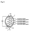
- the conductance catheter method is a known method that directly measures the ventricular volume. As shown in Figure 9, this method requires a conductance catheter (3) composed of several (5 in the example shown in the figure) segments (31s 1 to 31s 5 ) along the longitudinal direction.
- This catheter is inserted into the apical portion of the heart (H) and directed toward the aortic valve.
- a weak current with specific high frequencies flows constantly between the electrodes (32d 1 and 32d 6 ) at the two ends of this catheter (3).
- the voltage between the electrodes (32d 2 and 32d 3 ) (32d 3 and 32d 4 , or 32d 4 and 32d 5 ) at two ends of each of the inner segments (31s 2 ) (31s 3 or 31s 4 ) is measured.
- This change in electric field, or change in conductance is measured as voltage change between the electrodes (32d 2 and 32d 3 ) (32d 3 and 32d 4 , or 32d 4 and 32d 5 ) at the two ends of segment 31s 2 (31s 3 or 31 s 4 ).
- Figure 10 shows the wave diagrams of the signals obtained from the above conductance catheter.
- (A) to (C) show the voltage changes between electrodes at the two end of the each of the inner segments.
- (D) shows the intracardiac electrocardiographic signals.
- the ventricular volume can be calculated by measuring the conductance at each segment.
- the conductance catheter used in the conductance catheter method is known to be disclosed in, for example, Japan patent publication No. 269136/1993 or Japan patent publication No. 1372090/1998.
- This invention is a device for continuous ventricular volume measurements by automatic procedures using a conductance catheter.
- the conductance catheter inserted into the ventricle allows the measurement of blood conductivity and parallel conductance, which are regarded as essential for calculating ventricular volume from the conductance measured from the conductance catheter, thereby obviating the need for special procedures such as blood sampling and hypertonic saline infusion. Therefore, it is an automatic, continuous measuring device for a ventricle volume that allows automatic and moreover continuous measurement of ventricular volume even though the operator is not at the side of the animal implanted with a conductance catheter.
- the invention described in claim 1 concerns an automatic, continuous measuring device for a ventricle volume with the following features: that it is furnished with a multifunction catheter to be inserted into the ventricle and a power supply unit that supplies the necessary current to the above-mentioned multifunction catheter; and that the above-mentioned multifunction catheter is composed of two parts - a conductance catheter divided into multiple segments with electrodes interposed at fixed intervals such that an arbitrary high-frequency weak current is passed between the two end electrodes among the above-mentioned electrodes while the voltage differences between each of the segments except the two end segments are measured, and an electrode for measuring blood conductivity placed in one of the above-mentioned multiple segments.
- the invention described in claim 2 concerns an automatic, continuous measuring device for a ventricle volume with the following features: that it is furnished with a multifunction catheter to be inserted into the ventricle and a power supply unit that supplies the necessary current to the above-mentioned multifunction catheter; that the above-mentioned multifunction catheter is composed of two parts - a conductance catheter divided into at least three segments with at least four electrodes fitted at fixed intervals such that an arbitrary high-frequency weak current is passed between the two end electrodes among the above-mentioned electrodes while the voltage differences between each of the segments except the two end segments are measured, and 4 electrodes for measuring blood conductivity placed in one of the above-mentioned segments; and that among the above-mentioned four electrodes, the two end electrodes are designated current input electrodes and the pair of inner electrodes is designated voltage measurement electrodes.
- the invention described in claim 3 concerns an automatic, continuous measuring device for a ventricle volume described in claim 1 or claim 2 with the following feature: that the above-mentioned power supply unit is configurated so as to be able to supply a weak current at two frequencies between the two electrodes at the two ends of the above-mentioned multifunction catheter.
- the invention described in claim 4 concerns an automatic, continuous measuring device for a ventricle volume described in claim 1 or claim 2 with the following feature: that the above-mentioned power supply unit is configurated so as to be able to supply a weak current at three or more frequencies between the two electrodes at the two ends of the above-mentioned multifunction catheter; and that individual ventricular conductances are measured with three or more arbitrary frequencies supplied to the electrodes at the two ends of the above-mentioned multifunction catheter, and the two frequencies that provide the greatest difference in conductance are used to determine parallel conductance.
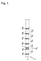
- Figure 1 is an enlarged drawing of a part of the multifunction catheter.
- Figure 2 is a block diagram showing the outline of the automatic, continuous measuring device for a ventricle volume concerning the first embodiment of this invention.
- the automatic, continuous measuring device for a ventricle volume (1) concerning the first embodiment of this invention is composed of a multifunction catheter (2), a power supply unit (5) and the main unit (9).
- the multifunction catheter (2) is to be inserted into the ventricle, and consists of a conductance catheter (3) and an electrode for measuring blood conductivity (4), as shown in an enlarged diagram in Figure 1.
- the conductance electrode (3) is similar to the conventional conductance catheter as explained in Figure 8, and is composed of multiple (five in the example shown in the figure) segments (31s 1 to 31s 5 ) interposed with electrodes (32d 1 and 32d 6 ) at fixed intervals.
- the multiple (five in the example shown in the figure) segments (31s 1 to 31s 5 ) each with electrodes at the two ends are arranged together along the longitudinal direction.
- an arbitrary high-frequency weak current such as 20 KHz and 3-5 ⁇ A supplied from a power supply unit to be described later is passed between the two electrodes (32d 1 and 32d 6 ) located at the outer side of the two end segments (31s 1 and 31s 5 , respectively).
- the voltage changes for the remaining segments (31s 2 to 31s 4 ) (thereinafter referred to as conductance measuring segments) except the two end segments (31s 1 and 31s 5 ) are measured.
- the number of conductance measuring segments and the inter-electrode distance of the electrodes are not restricted, and these can be set appropriately according to the size of the heart to be measured. In general, it is considered that at least one conductance measuring segment is required to measure voltage changes in the case of measuring the ventricular volume of the mouse heart, at least three conductance measuring segments to measure voltage changes in the case of measuring the ventricular volume of the rat heart, and at least five conductance measuring segments to measure voltage changes in the case of measuring the ventricular volume of the human heart.
- the electrodes can be placed at distances that allows placement of the above-mentioned number of conductance measuring segments. For example, in the case of measuring the ventricular volume of the rat heart, setting an inter-electrode distance of approximately 2 mm will allow adequate space for the above-mentioned number of conductance measuring segments.
- the electrode for measuring blood conductivity (4) is placed at one of the above-mentioned multiple segments. In other words, it is placed close to one (32d 2 in the figure) of the above-mentioned multiple electrodes (32d 1 to 32d 6 ), and blood conductivity is measured by the two electrodes (4 and 32d 2 ) at the two ends of the segment (31 s 6 ) by the two-electrode measurement method.
- the reason for placing the electrode for measuring blood conductivity close to one (32d 2 in the figure) of the above-mentioned multiple electrodes (32d 1 to 32d 6 ) is that since the cardiac volume changes constantly as a result of heart beat, blood conductivity cannot be measured due to the pulse-induced volume changes if the electrode for measuring blood conductivity (4) is far apart from one other of the above-mentioned multiple electrodes (32d 1 to 32d 6 ).
- the electrode for measuring blood conductivity and one of the above-mentioned multiple electrodes are placed at a distance that is not affected by the ventricular volume change accompanying beating of the heart; in other words, at a close enough distance such that the current from one electrode is converged only within the ventricular blood.
- the power supply unit (5) consists of a battery (51), a high frequency power circuit (52) and a frequency modulating circuit (53).
- the battery (51) supplies the necessary power to all parts of the signal detectors (7) and all parts of the automatic, continuous measuring device for a ventricle volume (1).
- the high frequency power circuit (52) supplies an arbitrary high-frequency weak current that flows between the two electrodes (32d 1 and 32d 6 ) at the two ends of the conductance catheter (3).
- the frequency modulating circuit (53) is installed so that the frequency of the weak current supplied to the conductance catheter (3) can be modulated arbitrarily.
- the parallel conductance derived from the myocardium and other sources can be estimated by measuring ventricular conductance using two predetermined frequencies such as "20 KHz and 2 KHz", it is also possible to measure the ventricular conductance individually using three or more arbitrary frequencies (for example, 2 KHz, 20 KHz and 30 KHz) and then choose the two frequencies (for example, 2 KHz and 30 KHz) that give the greatest difference in conductance, and use them to determine parallel conductance.
- the parallel conductance which is conventionally measured by hypertonic saline infusion and other methods, can be measured without special procedures and, moreover, with higher precision.
- the signal detector (7) is the part that detects ventricular volume signals, intracardiac electrocardiographic signals and blood conductivity signals from the multifunction catheter (2).
- the signal input side consists of multiple (three in the figure) signal detectors (7a, 7b and 7c) (hereinafter referred to as 7 collectively) for detecting conductance signals that are the ventricular volume signals, one signal detector (8) for intracardiac electrocardiographic signals, and one signal detector (6) for blood conductivity signals. From these signal detectors (6, 7 and 8), the detected signals are output via four or more channels (five channels in the figure).
- the detectors (7) for ventricular volume signals are installed corresponding to the three conductance measuring segments (31s 2 , 32s 3 , 32s 4 ) in the inner part of the conductance catheter (3). They are composed of differential amplifiers (71a, 71 b, 71c) to measure signals from the electrodes (32d 2 and 32d 3 ) (32d 3 and 32d 4 , or 32d 4 and 32d 5 ) at the two ends of each of the inner conductance measuring segments (31 s 2 ) (31 s 3 or 31s 4 ), band pass filters (72a, 72b and 72c), and wave detectors (73a, 73b and 73c).
- the band pass filters (72a, 72b and 72c) eliminate contamination by other signals such as intracardiac electrocardiographic signals.
- the wave detectors (73a, 73b and 73c) cut off the high frequency components from the output of the band pass filters (72a, 72b and 72c) and extract the low frequency components.
- the signal detector (8) for intracardiac electrocardiographic signals consists of a differential amplifier (81) connected to the two electrodes (32d 1 and 32d 5 ) at the two ends of the conductance catheter (3), and a band pass filter (82).
- the signal detector (6) for blood conductivity signals consists of a differential amplifier (61) connected to the electrode for measuring blood conductivity (4) and a electrode (32d 2 in the figure) located close to the above electrode, and a band pass filter (62).
- a pressure sensor (not shown in the figure) for measuring ventricular pressure may also be installed in the above-mentioned multifunction catheter (2).
- a pressure sensor By installing a pressure sensor, the state of the heart can be monitored more precisely.
- the type of pressure sensor is not restricted, but use of a piezo-resistant element is desirable. The reason is that this type of sensor is superior with respect to response to mild pressure changes, and is able to accurately measure the mild changes of ventricle pressure compared to pressure sensors using piezoelectric element.
- a bias alternating voltage is input from the power supply unit (5).
- the signals detected by the pressure sensor is sent to a signal detector (not shown in the figure) for ventricular pressure signals, which has a differential amplifier (not shown in the figure), and are then output from the signal detector as ventricular pressure signals.
- the signals output from the above-mentioned signal detectors (6, 7 and 8) are sent to the computing and processing unit (not shown in the figure) and undergo specified processing.
- these signals can be sent either by wired or wireless route.
- the signals output from various signal detectors (6, 7 and 8) are sent to a multiple converter.
- the signals from various channels are sampled in sequence, and converted to pulse position modulation (PPM wave) in the order of sampling, and the signals from multiple channels are subjected to time-division multiplexing.
- PPM wave pulse position modulation
- the pulse sequences of the modulated pulses including signals from multiple channels are superimposed on fixed carrier waves and transmitted by the transmission unit.
- the multifunction catheter (2) is inserted into the ventricle. In this case, thoracotomy is performed under anesthesia. After the multifunction catheter (2) is placed in the heart, the animal/subject is allowed to recover to a conscious state and return to a free-moving usual life.
- the conductance catheter (3) portion of the multifunction catheter (2) independently generates intracardiac electrocardiographic signals and conductance signals that are ventricular volume signals. These signals are detected by the corresponding signal detectors (7a, 7b, 7c and 8), amplified, and transmitted to the computing and processing units, etc. In addition, blood conductivity signals are generated and detected by the corresponding signal detector (6), amplified, and transmitted to the computing and processing unit.
- intracardiac electrocardiographic signals can be calculated in addition to the ventricular volume signals, which allows even more precise evaluation of the cardiac function.
- blood conductivity can be determined using the electrode for measuring blood conductivity (4) and the electrode (32d 2 in the figure) in close proximity of the above electrode. For this reason, there is no need to perform blood sampling separately to measure blood conductivity for calculating ventricular volume. For instance, ventricular volume can be measured even when the experimental animals and the study operators are remotely located from each other.
- parallel conductance can be determined by measuring the conductances using different frequencies, and then multiplying the difference in the above conductances by the coefficient.
- the automatic, continuous measuring device for a ventricle volume concerning the second embodiment of this invention differs from the automatic, continuous measuring device for a ventricle volume concerning the first embodiment by the following aspect.
- blood conductivity is measured by the two-electrode measurement method using an electrode for measuring blood conductivity placed close to one of the multiple electrodes.
- blood conductivity is measured by the four-electrode measurement method.
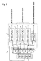
- Figure 3 is the block diagram showing the outline of the automatic, continuous measuring device for a ventricle volume concerning the second embodiment of this invention.
- Figure 4 is the block diagram of the part around the electrode for measuring blood conductivity (41), enlarged and extracted from the block diagram of the automatic, continuous measuring device for a ventricle volume shown in Figure 3. Some components not essential for the explanation of Figure 4 have been omitted.
- the electrode for measuring blood conductivity (41) is placed in one of the segments (31s 1 to 31s 5 ). In Figures 3 and 4, it is placed in segment (31s 2 ).
- the electrode for measuring blood conductivity (41) is composed of 4 electrodes (41a to 41d) placed in fixed intervals.
- the electrode pair at the two ends (41 a and 41d) are current input electrodes, and the pair of electrodes (41 b and 41c) located in between the current input electrodes are voltage measurement electrodes.
- the blood between the current input electrodes (41a and 41 d) When a current flows between the current input electrodes (41 a and 41 d), the blood between the current input electrodes (41a and 41 d) generate potential differences depending on the conductivity and distance. By measuring the voltage between the pair of voltage measurement electrodes (41b and 41 c) placed at equidistance between the current input electrodes (41a and 41d), the blood conductivity corresponding to the current can be measured.
- the distances between the four electrodes (41a to 41d) are not specifically restricted.
- the four electrodes (41 a to 41 d) can be placed at intervals of 0.1 mm.
- the power supply unit (5) consists of a battery (51), a high frequency power circuit (52a) and a frequency modulating circuit (53a).
- the battery (51) supplies the necessary power to all parts of the signal detectors (7) and all parts of the automatic, continuous measuring device for a ventricle volume (1).
- the high frequency power circuit (52a) supplies an arbitrary high-frequency weak current that flows between the two electrodes (32d 1 and 32d 6 ) at the two ends of the conductance catheter (3).
- a frequency modulating circuit (53a) is installed so that the frequency of the weak current supplied to the conductance catheter (3) can be modulated arbitrarily.
- the parallel conductance derived from the myocardium and other sources can be estimated by measuring ventricular conductance using two predetermined frequencies such as "20 KHz and 2 KHz", it is also possible to measure the ventricular conductance individually using three or more arbitrary frequencies (for example, 2 KHz, 20 KHz and 30 KHz) and then choose the two frequencies (for example, 2 KHz and 30 KHz) that give the greatest difference in conductance, and use them to measure parallel conductance.
- the parallel conductance which is conventionally measured by hypertonic saline infusion and other methods, can be measured without special procedures and, moreover, with higher precision.
- the power supply unit (5) contains a high frequency power circuit (52b) and a frequency modulating circuit (53b). Through the power supply from the high frequency power circuit (52b), an arbitrary high-frequency weak current flows between the current input electrodes (41 a and 41 d) at the two ends of the electrode for measuring blood conductivity (4) fitted in the conductance catheter (3).
- the frequency modulating circuit (53b) is installed so that the frequency of the weak current supplied by the current input electrodes (41a and 41d) can be modulated arbitrarily.
- the signal detector (7) is the part that detects ventricular volume signals, intracardiac electrocardiographic signals and blood conductivity signals obtained from the multifunction catheter (2).
- the signal input side consists of multiple (three in the figure) signal detectors (7a, 7b and 7c) (hereinafter referred to collectively as 7) for detecting conductance signals that are the ventricular volume signals, one signal detector (8) for intracardiac electrocardiographic signals, and one signal detector (6) for blood conductivity signals. From these signal detectors (6, 7 and 8), the detected signals are output via four or more channels (five channels in the figure).
- the detectors for ventricle volume signals are installed corresponding to the three conductance measuring segments (31s 2 , 32s 3 and 32s 4 ) in the inner portion of the conductance catheter (3). They consist of differential amplifiers (71a, 71b and 71c) to measure signals from the electrodes (32d 2 and 32d 3 ) (32d 3 and 32d 4 , or 32d 4 and 32d 5 ) at the two ends of each of the inner conductance measuring segments (31s 2 ) (31s 3 or 31s 4 ), band pass filters (72a, 72b and 72c), and wave detectors (73a, 73b and 73c).
- the band pass filters (72a, 72b and 72c) eliminate contamination by other signals such as intracardiac electrocardiographic signals.
- the wave detectors (73a, 73b and 73c) cut off the high frequency components from the output of the band pass filters (72a, 72b and 72c) and extract the low frequency components.
- the signal detector (8) for intracardiac electrocardiographic signals consists of a differential amplifier (81) connected to the two electrodes (32d 1 and 32d 5 ) at the two ends of the conductance catheter (3), and a band pass filter (82).
- the signal detector (6) for blood conductivity signals consists of a differential amplifier (61) connected to the two central electrodes for measuring blood conductivity (41 b and 41 c), and a band pass filter (62).
- the conductance catheter (3) When the conductance catheter (3) is inserted into the heart for a long period of time, the blood components may adhere to the surrounding of the conductance catheter (3). When blood conductivity is measured by two-electrode measurement, the blood components attached to the surrounding of the conductance catheter (3) change the voltage, and accurate measurement of blood conductivity may not be possible.
- the multifunction catheter (2) is inserted into the ventricle. In this case, thoracotomy is performed under anesthesia. After the multifunction catheter (2) is placed in the heart, the animal/subject is allowed to recover to a conscious state and return to a free-moving usual life.
- the conductance catheter (3) portion of the multifunction catheter (2) After starting the device that has been set as above-mentioned, the conductance catheter (3) portion of the multifunction catheter (2) generates intracardiac electrocardiographic signals and conductance signals that are ventricular volume signals. These signals are detected by the corresponding signal detectors (7a, 7b, 7c and 8), amplified, and transmitted to the computing and processing units, etc. In addition, blood conductivity signals are generated and detected by the corresponding signal detector (6), amplified, and transmitted to the computing and processing unit.
- blood conductivity can be measured by the four-electrode measurement method using electrodes for measuring blood conductivity (41) composed of a pair of current input electrodes (41 a and 41 d) and a pair of voltage measurement electrodes (41b and 41c). For this reason, there is no need to perform blood sampling separately to measure blood conductivity for the calculation of ventricular volume. For instance, ventricular volume can be measured even when the experimental animals and the study operators are physically remote from each other. Furthermore, this method has less measurement error compared to the two-electrode measurement method for measuring blood conductivity, and more precise measurement of ventricular volume is thus possible.
- the automatic, continuous measuring device for a ventricle volume (1) concerning the first and second embodiments is well suited for use in small animals such as rats and mice; as well as in large animals such as dogs, cats, cows, sheep, horses and humans.
- an electrode for measuring blood conductivity close to one of the electrodes installed in the conductance catheter obviates the need to collect blood and measure blood conductivity separately. For that reason, for instance, ventricular volume can be measured continuously even when the experimental animals and the operators are physically remote from each other.
- the device since the device is able to supply a weak current of two frequencies to the electrodes at the two ends of the multifunction catheter, conductances for two different frequencies can be measured. Therefore, by calculating the difference of the above-mentioned conductances, the conductance derived from the myocardium and other sources can be determined. Using the previously determined coefficient, the parallel conductance can be calculated. This method permits automatic measurement of ventricular volume continuously without the need to measure parallel conductance of the experimental animal by conventional methods such as saline infusion.
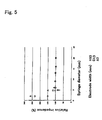
- the relative impedance decreased with increase in syringe diameter for all the electrode types, and the relative impedance reached 100% at syringe diameters of 10 mm and greater for all the inter-electrode distances.
- impedance decrease was observed with smaller syringe diameters.
- the relative impedance was 100% at a syringe diameter of 5 mm.
- the above results indicate that when the inter-electrode distance is within 3 mm, the effective conductivity volume can be focused within diameter of 10 mm vertical to the catheter, and when the distance between two electrodes is 0.5 mm, it can be focused within a diameter of 5 mm.
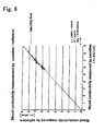
- a conductance catheter was placed into the left ventricle of a Japanese white rabbit.
- the conductance catheter had an electrode for measuring blood conductivity placed 0.5 mm from one (third electrode from the catheter tip) of 7 electrodes that formed the conductance catheter.
- a high-frequency current of 20 KHz and 30 pA was passed between the two ends of the conductance catheter and the blood conductivity ( ⁇ v) was measured.
- blood was collected from the same Japanese white rabbit and the blood conductivity ( ⁇ c) was measured using a special cuvette.
- the X axis in Figure 6 is the blood conductivity measured by the cuvette ( ⁇ c) and the Y axis is the blood conductivity measured by the catheter ( ⁇ v).
- GpSAL nine Japanese white rabbits were randomly selected and parallel conductance at 20 KHz (GpSAL) was measured by the saline infusion method.
- GpSAL : ⁇ G 2KHz-20KHz ratio was calculated for each Japanese white rabbit, and the mean value was 9.158 ( ⁇ 0.558).
- the automatic, continuous measuring device for a ventricle volume permits measurement of blood conductivity and parallel conductance, which are regarded as essential for calculating ventricular volume from the conductance measured by a conductance catheter, by using the conductance catheter inserted into the ventricle without special procedures such as blood sampling and saline infusion. It allows automatic and, moreover, continuous measurement of the ventricular volume even when the operator is not physically close to the animal implanted with the conductance catheter.
Landscapes
- Health & Medical Sciences (AREA)
- Life Sciences & Earth Sciences (AREA)
- General Health & Medical Sciences (AREA)
- Public Health (AREA)
- Pathology (AREA)
- Engineering & Computer Science (AREA)
- Biomedical Technology (AREA)
- Heart & Thoracic Surgery (AREA)
- Medical Informatics (AREA)
- Molecular Biology (AREA)
- Surgery (AREA)
- Veterinary Medicine (AREA)
- Biophysics (AREA)
- Physics & Mathematics (AREA)
- Animal Behavior & Ethology (AREA)
- Dentistry (AREA)
- Oral & Maxillofacial Surgery (AREA)
- Nuclear Medicine, Radiotherapy & Molecular Imaging (AREA)
- Radiology & Medical Imaging (AREA)
- Hematology (AREA)
- Cardiology (AREA)
- Physiology (AREA)
- Measurement And Recording Of Electrical Phenomena And Electrical Characteristics Of The Living Body (AREA)
- Measuring Pulse, Heart Rate, Blood Pressure Or Blood Flow (AREA)
Abstract
Description
Claims (4)
- An automatic, continuous measuring device for a ventricle volume (1) characterized by the following: furnished with a multifunction catheter (2) to be introduced into the ventricle, and a power supply unit (5) to supply the necessary current to the above-mentioned multifunction catheter (2);
The above-mentioned multifunction catheter (2) consists of two parts - a conductance catheter (3) made up of multiple segments interposed with electrodes at fixed intervals such that an arbitrary high-frequency weak current is passed between the two end electrodes while the voltages are measured in the other segments except the two end segments, and an electrode for measuring blood conductivity (4) placed at one of the above-mentioned multiple segments. - An automatic, continuous measuring device for a ventricle volume (1) characterized by the following: furnished with a multifunction catheter (2) to be introduced into the ventricle, and a power supply unit (5) to supply the necessary current to the above-mentioned multifunction catheter (2);
The above-mentioned multifunction catheter (2) consists of two parts - a conductance catheter (3) made up of at least three segments interposed with at least four electrodes such that an arbitrary high-frequency weak current is passed between the two end electrodes while the voltages are measured in all segments except the two end segments, and four electrodes (41) for measuring blood conductivity placed in one of the above-mentioned multiple segments;
Of the above-mentioned four electrodes (41) for measuring blood conductivity, the electrodes at two ends are designated current input electrodes (41 a and 41d) and the inner pair of electrodes is designated voltage measurement electrodes (41 b and 41 c). - An automatic, continuous measuring device for a ventricle volume (1) described in claim 1 or claim 2 characterized by the following: the above-mentioned power supply unit (5) is configurated so as to be able to supply a weak current at two frequencies between the two electrodes at the two ends of the above-mentioned multifunction catheter (2).
- An automatic, continuous measuring device for a ventricle volume (1) described in claim 1 or claim 2 characterized by the following: the above-mentioned power supply unit (5) is configurated so as to be able to supply a weak current at three or more frequencies between the two electrodes at the two ends of the above-mentioned multifunction catheter (2);
Individual ventricular conductances are measured with three or more arbitrary frequencies supplied to the electrodes at the two ends of the above-mentioned multifunction catheter (2), and the two frequencies that provide the greatest difference in conductance are used to determine parallel conductance.
Applications Claiming Priority (3)
| Application Number | Priority Date | Filing Date | Title |
|---|---|---|---|
| JP2001286997 | 2001-09-20 | ||
| JP2001286997 | 2001-09-20 | ||
| PCT/JP2002/009655 WO2003026504A1 (en) | 2001-09-20 | 2002-09-19 | Automatic, continuous measuring device for a ventricle volume |
Publications (2)
| Publication Number | Publication Date |
|---|---|
| EP1437090A1 true EP1437090A1 (en) | 2004-07-14 |
| EP1437090A4 EP1437090A4 (en) | 2006-03-01 |
Family
ID=19109884
Family Applications (1)
| Application Number | Title | Priority Date | Filing Date |
|---|---|---|---|
| EP02799489A Withdrawn EP1437090A4 (en) | 2001-09-20 | 2002-09-19 | DEVICE FOR MEASURING, AUTOMATICALLY AND CONTINUOUSLY, VENTRICULAR VOLUME |
Country Status (5)
| Country | Link |
|---|---|
| US (1) | US20040254436A1 (en) |
| EP (1) | EP1437090A4 (en) |
| JP (1) | JP4189551B2 (en) |
| CA (1) | CA2460186A1 (en) |
| WO (1) | WO2003026504A1 (en) |
Cited By (3)
| Publication number | Priority date | Publication date | Assignee | Title |
|---|---|---|---|---|
| WO2006102905A1 (en) * | 2005-03-31 | 2006-10-05 | Gregersen Enterprises 2005 Aps | Apparatus and method for a global model of hollow internal organs including the determination of cross-sectional areas and volume in internal hollow organs and wall properties |
| EP1667577A4 (en) * | 2003-09-09 | 2010-03-03 | Univ Texas | METHOD AND APPARATUS FOR MEASURING CARDIAC POWER IN A PATIENT USING A CONDUCTANCE CATHETER |
| EP1919355A4 (en) * | 2005-08-22 | 2011-04-20 | Scisense Inc | IMPLANTED TRANSMITTER |
Families Citing this family (1)
| Publication number | Priority date | Publication date | Assignee | Title |
|---|---|---|---|---|
| WO2008091557A2 (en) * | 2007-01-23 | 2008-07-31 | Cvdevices, Llc | Devices, systems, and methods to evaluate cardiovascular function |
Family Cites Families (7)
| Publication number | Priority date | Publication date | Assignee | Title |
|---|---|---|---|---|
| US4840182A (en) * | 1988-04-04 | 1989-06-20 | Rhode Island Hospital | Conductance catheter |
| JP3092027B2 (en) | 1992-03-23 | 2000-09-25 | 科学技術振興事業団 | Ventricular volume measuring method and catheter for measurement |
| US5842998A (en) * | 1996-08-21 | 1998-12-01 | Cleveland Clinic Foundation | Apparatus for determining the conductivity of blood |
| JPH10137209A (en) * | 1996-11-07 | 1998-05-26 | Haruo Ito | Electrode catheter for ventricular volume measurement |
| US6112115A (en) * | 1999-03-09 | 2000-08-29 | Feldman; Marc D. | Method and apparatus for determining cardiac performance in a patient |
| JP2001137209A (en) * | 1999-11-17 | 2001-05-22 | Star Medical Kk | Ventricular volume measuring apparatus |
| JP2002143109A (en) * | 2000-11-13 | 2002-05-21 | Natl Space Development Agency Of Japan | Simultaneous continuous measurement of ventricular volume and ventricular pressure for small animal implantation |
-
2002
- 2002-09-19 WO PCT/JP2002/009655 patent/WO2003026504A1/en not_active Ceased
- 2002-09-19 EP EP02799489A patent/EP1437090A4/en not_active Withdrawn
- 2002-09-19 US US10/489,120 patent/US20040254436A1/en not_active Abandoned
- 2002-09-19 JP JP2003530148A patent/JP4189551B2/en not_active Expired - Fee Related
- 2002-09-19 CA CA002460186A patent/CA2460186A1/en not_active Abandoned
Cited By (4)
| Publication number | Priority date | Publication date | Assignee | Title |
|---|---|---|---|---|
| EP1667577A4 (en) * | 2003-09-09 | 2010-03-03 | Univ Texas | METHOD AND APPARATUS FOR MEASURING CARDIAC POWER IN A PATIENT USING A CONDUCTANCE CATHETER |
| WO2006102905A1 (en) * | 2005-03-31 | 2006-10-05 | Gregersen Enterprises 2005 Aps | Apparatus and method for a global model of hollow internal organs including the determination of cross-sectional areas and volume in internal hollow organs and wall properties |
| EP1919355A4 (en) * | 2005-08-22 | 2011-04-20 | Scisense Inc | IMPLANTED TRANSMITTER |
| US8460198B2 (en) | 2005-08-22 | 2013-06-11 | Scisense Inc. | Implant transmitter |
Also Published As
| Publication number | Publication date |
|---|---|
| EP1437090A4 (en) | 2006-03-01 |
| WO2003026504B1 (en) | 2003-09-25 |
| US20040254436A1 (en) | 2004-12-16 |
| JPWO2003026504A1 (en) | 2005-01-06 |
| WO2003026504A1 (en) | 2003-04-03 |
| CA2460186A1 (en) | 2003-04-03 |
| JP4189551B2 (en) | 2008-12-03 |
Similar Documents
| Publication | Publication Date | Title |
|---|---|---|
| US20230240577A1 (en) | Multi-electrode impedance sensing | |
| EP0553187B1 (en) | A device for measurement of electrical impedance of organic and biological materials | |
| US7104947B2 (en) | Determining stimulation levels for transcranial magnetic stimulation | |
| US11241281B2 (en) | Estimation of electrode-tissue contact using oscillator at common ground of electrocardiogram (ECG) system | |
| EP2561805B1 (en) | Apparatus and method for measuring bioelectric signals | |
| US5246008A (en) | Method for monitoring a patient for rejection reactions to an implanted heart | |
| IL275215B2 (en) | Extension of electrocardiography (ecg) acquisition capabilities of catheter-based cardiac system | |
| JP2008543453A (en) | Electrode and method for determining biopotential | |
| KR101879634B1 (en) | Monitoring system for cardiopulmonary vessel | |
| WO2003092495A1 (en) | Intracavitary impedance measuring probe | |
| US20040254436A1 (en) | Automatic continuous measuring device for ventricle volume | |
| EP3202319B1 (en) | Method for detecting position of signal source in living body, and device for detecting position of signal source in living body | |
| JP5061011B2 (en) | Pacemaker pulse detector | |
| US10542941B2 (en) | Integrated assessment of electrical activation and myocardial strain | |
| JPS63109840A (en) | Multielectrode type living body electric impedance measuring method | |
| JP3909710B2 (en) | Ventricular volume measuring device and ventricular volume measuring method | |
| RU2082315C1 (en) | Device for setting diagnosis based on biologically active points state | |
| US20100262023A1 (en) | Power approach to biomedical signal analysis | |
| JPH0347096B2 (en) | ||
| JP2001526074A (en) | Non-invasive device for electromyographic measurements | |
| Hoffmann et al. | Recording and processing of biosignals | |
| UA34541A (en) | Generator for electroimpedance measuring of biological objects |
Legal Events
| Date | Code | Title | Description |
|---|---|---|---|
| PUAI | Public reference made under article 153(3) epc to a published international application that has entered the european phase |
Free format text: ORIGINAL CODE: 0009012 |
|
| 17P | Request for examination filed |
Effective date: 20040405 |
|
| AK | Designated contracting states |
Kind code of ref document: A1 Designated state(s): AT BE BG CH CY CZ DE DK EE ES FI FR GB GR IE IT LI LU MC NL PT SE SK TR |
|
| RIN1 | Information on inventor provided before grant (corrected) |
Inventor name: SUNAGAWA, KENJI Inventor name: UEMURA, KAZUNORI |
|
| A4 | Supplementary search report drawn up and despatched |
Effective date: 20060118 |
|
| STAA | Information on the status of an ep patent application or granted ep patent |
Free format text: STATUS: THE APPLICATION HAS BEEN WITHDRAWN |
|
| REG | Reference to a national code |
Ref country code: DE Ref legal event code: 8566 |
|
| 18W | Application withdrawn |
Effective date: 20060412 |