EP1435841B1 - A method of assessing the effect of a conduit section on flow characteristics of a first fluid - Google Patents
A method of assessing the effect of a conduit section on flow characteristics of a first fluid Download PDFInfo
- Publication number
- EP1435841B1 EP1435841B1 EP02798778A EP02798778A EP1435841B1 EP 1435841 B1 EP1435841 B1 EP 1435841B1 EP 02798778 A EP02798778 A EP 02798778A EP 02798778 A EP02798778 A EP 02798778A EP 1435841 B1 EP1435841 B1 EP 1435841B1
- Authority
- EP
- European Patent Office
- Prior art keywords
- flow
- fluid
- tubing
- conduit
- transverse
- Prior art date
- Legal status (The legal status is an assumption and is not a legal conclusion. Google has not performed a legal analysis and makes no representation as to the accuracy of the status listed.)
- Expired - Lifetime
Links
- 239000012530 fluid Substances 0.000 title claims abstract description 49
- 238000000034 method Methods 0.000 title claims abstract description 25
- 230000000694 effects Effects 0.000 title claims abstract description 24
- 238000012360 testing method Methods 0.000 claims description 39
- 238000002604 ultrasonography Methods 0.000 claims description 17
- 230000015572 biosynthetic process Effects 0.000 claims description 13
- 238000011144 upstream manufacturing Methods 0.000 claims description 12
- 208000031481 Pathologic Constriction Diseases 0.000 description 17
- 238000005259 measurement Methods 0.000 description 13
- 238000005755 formation reaction Methods 0.000 description 12
- 208000037804 stenosis Diseases 0.000 description 11
- 230000036262 stenosis Effects 0.000 description 11
- 230000017531 blood circulation Effects 0.000 description 7
- 239000007788 liquid Substances 0.000 description 7
- 239000008280 blood Substances 0.000 description 6
- 210000004369 blood Anatomy 0.000 description 6
- 210000001367 artery Anatomy 0.000 description 5
- 238000013461 design Methods 0.000 description 4
- 230000000541 pulsatile effect Effects 0.000 description 4
- 239000000523 sample Substances 0.000 description 4
- 238000001514 detection method Methods 0.000 description 3
- 238000001727 in vivo Methods 0.000 description 3
- 210000003462 vein Anatomy 0.000 description 3
- 210000004204 blood vessel Anatomy 0.000 description 2
- 238000002595 magnetic resonance imaging Methods 0.000 description 2
- 230000000704 physical effect Effects 0.000 description 2
- 230000035899 viability Effects 0.000 description 2
- 230000000007 visual effect Effects 0.000 description 2
- 201000001320 Atherosclerosis Diseases 0.000 description 1
- 238000013459 approach Methods 0.000 description 1
- 230000009286 beneficial effect Effects 0.000 description 1
- 230000001427 coherent effect Effects 0.000 description 1
- 238000010586 diagram Methods 0.000 description 1
- 238000002513 implantation Methods 0.000 description 1
- 238000003780 insertion Methods 0.000 description 1
- 230000037431 insertion Effects 0.000 description 1
- 238000011835 investigation Methods 0.000 description 1
- 230000003278 mimic effect Effects 0.000 description 1
- 239000000203 mixture Substances 0.000 description 1
- 239000003921 oil Substances 0.000 description 1
- 229920001296 polysiloxane Polymers 0.000 description 1
- 238000012545 processing Methods 0.000 description 1
- 230000002035 prolonged effect Effects 0.000 description 1
- 230000000644 propagated effect Effects 0.000 description 1
- 229910052710 silicon Inorganic materials 0.000 description 1
- 239000010703 silicon Substances 0.000 description 1
Images

Classifications
-
- A—HUMAN NECESSITIES
- A61—MEDICAL OR VETERINARY SCIENCE; HYGIENE
- A61B—DIAGNOSIS; SURGERY; IDENTIFICATION
- A61B8/00—Diagnosis using ultrasonic, sonic or infrasonic waves
- A61B8/06—Measuring blood flow
-
- A—HUMAN NECESSITIES
- A61—MEDICAL OR VETERINARY SCIENCE; HYGIENE
- A61B—DIAGNOSIS; SURGERY; IDENTIFICATION
- A61B8/00—Diagnosis using ultrasonic, sonic or infrasonic waves
- A61B8/12—Diagnosis using ultrasonic, sonic or infrasonic waves in body cavities or body tracts, e.g. by using catheters
-
- A—HUMAN NECESSITIES
- A61—MEDICAL OR VETERINARY SCIENCE; HYGIENE
- A61F—FILTERS IMPLANTABLE INTO BLOOD VESSELS; PROSTHESES; DEVICES PROVIDING PATENCY TO, OR PREVENTING COLLAPSING OF, TUBULAR STRUCTURES OF THE BODY, e.g. STENTS; ORTHOPAEDIC, NURSING OR CONTRACEPTIVE DEVICES; FOMENTATION; TREATMENT OR PROTECTION OF EYES OR EARS; BANDAGES, DRESSINGS OR ABSORBENT PADS; FIRST-AID KITS
- A61F2/00—Filters implantable into blood vessels; Prostheses, i.e. artificial substitutes or replacements for parts of the body; Appliances for connecting them with the body; Devices providing patency to, or preventing collapsing of, tubular structures of the body, e.g. stents
- A61F2/02—Prostheses implantable into the body
- A61F2/04—Hollow or tubular parts of organs, e.g. bladders, tracheae, bronchi or bile ducts
- A61F2/06—Blood vessels
- A61F2002/068—Modifying the blood flow model, e.g. by diffuser or deflector
Definitions
- This invention relates to a method of and apparatus for assessing the effect of a conduit section on flow characteristics of a first fluid.
- WO 00/38591 discloses the use of tubing, for example, blood flow tubing, with internal spiral formations to improve flow through the tubing in at least some respects.
- spiral flow induced by a spiral formation in an artery or graft can reduce or eliminate dead flow regions and turbulence, leading to reduced tendency of stenosis. The same effect is observed in industrial tubing and pipes.
- the effect depends upon the dimensions of the tubing and the properties of the fluid flow, its density, viscosity and its speed, as well as on the nature of the spiral formation.
- the problem is to specify an internal spiral formation, of a tube of given dimensions, that produces a beneficial effect; a further problem is to specify a formation which optimises the effect.
- Stonebridge et al disclose a method of studying spiral laminar flow in vivo using Doppler ultrasound in " Spiral laminar flow in vivo", Clinical Science, 1996, Vol. 91, pages 17-21 .
- the present invention is a method as defined in claim 1.
- the transverse flow parameter comprises transverse flow velocity, and typically, a number of transverse flow velocities are detected across a cross-section of the first conduit system.
- the transverse flow parameter is detected using ultrasound, and preferably, using a Doppler ultrasound technique.
- ultrasound and preferably, using a Doppler ultrasound technique.
- other detection methods are possible, such as magnetic resonance imaging (MRI).
- MRI magnetic resonance imaging
- the at least one transverse flow characteristic that is determined comprises a quantitative flow characteristic.
- the quantitative flow characteristic comprises peak transverse flow velocity.
- the quantitative flow characteristic also comprises spiral statistical uncertainty.
- the at least one transverse flow characteristic that is determined comprises a qualitative flow characteristic.
- the qualitative flow characteristic comprises one or more of transverse flow profile and transverse velocity profile.
- the pressure of the first fluid in the flow system is also detected.
- the pressure may be detected upstream and/or downstream of the conduit section.
- the invention may be used to assess the effect of the conduit section on the flow characteristics of a second fluid in a second conduit system.
- initially flow characteristics of the second conduit system are analysed, the first conduit system is configured to at least partially emulate the second conduit system, and a second assessment of the effect of the conduit section on the flow characteristics of a second fluid in the second conduit system are derived from the assessment of the effect of the conduit section on the flow characteristics of the first fluid in the first conduit system.
- the first fluid has a known relationship to the second fluid.
- the detecting region is a cross-section of the first conduit system.
- the sensing system is a Doppler ultrasound sensing system that comprises a source of ultrasonic waves and a sensor for detecting ultrasonic waves from the detecting region of the first conduit system.
- the first and second fluids are liquids.
- the first conduit system may comprise upstream and downstream tubing delivering fluid to and receiving it from the conduit section.
- the upstream tubing may be such as deliver specific amounts of turbulence in the flow and non-rotational flow to the conduit section, and the downstream tubing may be such as not to induce turbulence and/or rotation which could be propagated upstream.
- Smooth-walled tubing such as silicon or silicon-lined or silicone treated tubing will usually be found suitable.
- the first conduit system may comprise a source for the fluid and pressure means to provide a pressure head in the fluid.
- the pressure means may comprise a fluid reservoir elevated above the tube, and/or a pump.
- the fluid will be a liquid.
- the fluid will be blood, or, preferably, a liquid simulating blood, as by having comparable density and viscosity.
- the fluid may also have comparable acoustic refractive index.
- the effect of a stenosis may be observed by making measurements with and without such.
- An apertured plug may be inserted in the downstream tube of a flow system for this.
- Testing the effect of different stenosis values (stenosis value may be defined as the ratio of plug aperture to tube area) may be done by inserting a series of plugs with different stenosis values.
- Ultrasound measurements may be made on the downstream tubing, just downstream of the tube, and at differing distances from it, but upstream of the stenosis, to indicate how a spiral form graft will be affected over time by developing atherosclerosis, for example.
- pulsatile flow such as blood flow
- clearly pulsatile flow conditions can be imposed by control of a pump or a valve. Snapshot and/or time sequence measurements may be made.
- Measurement may give, for a tomographic slice of the tubing, a distribution of transverse velocity values against radius from the axis of the tubing.
- a distribution may be analysed by any convenient method.
- the distribution may be regarded as an image, which may be bit-mapped and subjected to image processing techniques.
- the method according to the invention indicates that single spiral formation tubing is best, and that downstream stenosis of no more than 44% stenosis value is sufficient to cancel any spiral flow induced by the spiral formation tube - this is rectangular linear profile stenosis.
- the internal spiral formation, in blood flow tubing, may be that of a stent.
- WO 00/38591 referred to above discloses stents with spiral formations that induce spiral flow in veins or arteries and such stents may also be assessed using the method of the invention.
- the set-up may be designed to mimic the site at which the stent will be implanted, by suitable choice of tube, and inlet and outlet tubing, and different stents tested, or a reconfigurable stent tested in different configurations, in order to optimise stent performance.
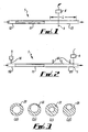
- Figure 1 shows a test tube 11 mounted in a test system 1 between an upstream tubing 12 and a downstream tubing 13.
- Figure 2 shows the test system 1 but with an alternative example of upstream tubing 112 and downstream tubing 113.
- the tubing 112, 113 has ports 14 which enable the pressure of the fluid in the tubing 112, 113 to be measured.
- a Döppler ultrasound probe 4 is located adjacent the downstream tubing 13, 113 of the test system 1 so that transverse flow velocities of fluid in the tube 13, 113 are detected across a plane 3 transverse to the tubing 13, 113.
- the probe 4 is movable mounted so that it can be moved in a direction parallel to the longitudinal axis of the tubing 13, 1 13 along the length "L".
- the Döppler ultrasound techniques enable the range and distribution of transverse flow velocities in the plane to be detected. Döppler ultrasound probes are commercially available, and details will not be elaborated here. Of particular interest is to see how spiral flow induced in the tube 11 is maintained downstream, and tomographic slices of fluid are observed at various positions in the downstream tubing 13, 113, within the available length "L".
- any suitable detection system could be used to detect the transverse flow velocities or another suitable transverse flow parameter.
- An example of another suitable detection system is a magnetic resonance imaging (MRI) system.
- MRI magnetic resonance imaging
- the test system 1 also comprises a source for the fluid and pressure means to provide a pressure head in the fluid, neither of which is shown.
- the pressure means may comprise a fluid reservoir elevated above the tube 11 and/or a pump.
- the fluid will usually be a liquid, and a liquid of particular interest is blood, it having been realised that the way blood flows in veins and arteries can have a major influence on the continued patency thereof.
- WO 00/38591 discusses how spiral formation in blood vessels can prevent build up of deposits on their walls to maintain healthy flow and militate against the formation of clots.
- Blood could be used for testing, but preferred is a liquid that simulates blood without the problems of maintaining its viability over prolonged tests.
- a mix of Shelley fluid and ATS mimics blood in terms of density, viscosity and acoustic refractive index, and is ideal for Döppler ultrasound measurements.
- the tubing 112, 113 includes pressure sensing ports 14 at various positions in the delivery and receiving tubing 112,113.
- the ports 14 each permit a pressure sensor 5 to be coupled to them to permit sensing of the pressure at the respective location in the respective tubing 112, 113.
- Typical testing stenoses are illustrated in Figures 3(a) to 3(d) in cross section.
- Figure 3(a) and 3(c) show coaxial stenoses 20, 21 respectively, with stenosis values (ratio of hatched blocked area to whole) of 44% and 75% respectively.
- Figures 3(b) and (d) show off-axis stenoses 22, 23 having the same values as the stenoses 20, 21, respectively.
- flow is pulsatile, and the flow system is adapted to produce pulsatile flow by suitable motor or valve control. Measurements can be snapshot or continuous over time.
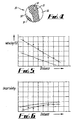
- Figure 4 shows a Döppler ultrasound scan 30. These are usually two-colour scans with one colour 31 (hatched area) indicating flow towards and the other colour 32 (unhatched) indicating flow away from the ultrasound source. The intensity of the colour (which cannot be shown in the drawing) indicates velocity.
- the scan 30 is generated from output signals output by the probe 4 to a processor 6, which processes the output signals and displays them as the scan 30 on an output device 7, such as a visual display.
- the processor 6 also processes the output signals using conventional numerical analysis techniques to obtain transverse flow profile, transverse velocity profile, peak transverse velocity and spiral statistical uncertainty. These can then be analysed along with the scan 30 to assess the effect of the test tube 11 in the test system.
- the spiral statistical uncertainty is effectively a percentage of v peak . If the spiral statistical uncertainty is greater than 100% this indicates that no spiral flow was detected. If the spiral statistical uncertainty is less than 100% this indicates that spiral flow was detected. The lower the percentage, the higher the amount of spiral flow detected. Hence, the spiral statistical uncertainty gives an indication of the quality of the spiral flow.
- the peak transverse velocity and the spiral statistical uncertainty provide quantitative indications of the effect of the test tube 11 on fluid flow in the tubing 13, 113.
- the linear flow characteristics i.e. the flow parallel to the longitudinal axis of the tubing 13,113
- the ratio of peak transverse velocity to peak linearvelocity provides an indication of the speed of travel of the spiral flow along the tubing 13, 113.
- the transverse flow profile and the transverse velocity profile can be displayed as graphs and used to proved qualitative indications of the effect of the test tube 11 on the fluid flow in the tubing 13, 113.
- the advantage of the scan 30 is that it provides a visual indication of the position and quality of the spiral flow pattern within the tubing 13, 113.
- tubing 112, 113 to assess the effect on the test tube 11 on fluid pressures upstream and downstream of the test tube 11. This is important to ensure that the flow pattern produced by the test tube 11 does not have the undesirable side effect of generating fluid pressures that are too high upstream and downstream of the test tube 11.
- Graft 1 was an 8mm diameter graft with a single internal fin, of helix angle 8°, the depth of the fin being 2mm.
- Graft 2 was a similar graft, but with two internal fins. It will be seen that the Spiral velocity is higher for Graft 1, and the Spiral statistical uncertainty lower than for Graft 2, indicating that Graft 1 is the better graft, at least by the applied standards.
- a flow system according to the invention will have desirably a sufficiently flexible design to accommodate grafts of different lengths and to investigate flow in downstream tubing at different distances, perhaps up to half a metre or more, from the graft under investigation. Fixtures and fittings will be provided facilitating the connection of tube of different diameters and for the insertion of stenoses. For the testing of stents, facilities will be provided for accommodating stents of different designs and for actuating stents which need to be deployed and manipulated in veins and arteries.
- the test system 1 can be used to replicate the conditions within an actual flow system by first analysing the flow in the actual flow system and then adjusting parameters of the test system 1 to replicate the actual system.
- Typical parameters that are analysed and then replicated in the test system 1 are physical properties of the fluid flowing through the test system 1, such as density and viscosity and physical properties of the test system 1, such as fluid pressure, flow velocity and any restrictions within the actual system.
- the processor 6 can be used to control the test system 1 to emulate the actual system by controlling test system controls 8.
- the test system controls 8 can control valves and/or a pump (not shown) in the test system 1.
- the effect of the conduit section 11 on the fluid flow in the test system 1 can be derived from the assessment of the effect of the conduit section on flow in the test system 1.
- the actual system could be any fluid flow system, and especially a system where the fluid is a liquid.
- the actual system could be an industrial pipeline system, such as an oil or gas pipeline, or a blood vessel system in the human or animal body.
- the invention has the advantage that it enables the effect of a conduit section 11 on fluid flow to be assessed in a test system before it is inserted into an actual system.
- the conduit section 11 may be, for example, designed to improve or alter the fluid flow pattern in the actual system. This may be, for example, to reduce turbulence, to alter the wall pressures, to reduce deposits forming within the conduit system and/or to improve flow in the region of a specific conduit geometry, such as a bifurcation or a restriction or enlargement.
Landscapes
- Health & Medical Sciences (AREA)
- Life Sciences & Earth Sciences (AREA)
- Molecular Biology (AREA)
- Heart & Thoracic Surgery (AREA)
- Biophysics (AREA)
- Nuclear Medicine, Radiotherapy & Molecular Imaging (AREA)
- Pathology (AREA)
- Radiology & Medical Imaging (AREA)
- Engineering & Computer Science (AREA)
- Animal Behavior & Ethology (AREA)
- Surgery (AREA)
- Medical Informatics (AREA)
- Physics & Mathematics (AREA)
- Veterinary Medicine (AREA)
- Biomedical Technology (AREA)
- General Health & Medical Sciences (AREA)
- Public Health (AREA)
- Hematology (AREA)
- Ultra Sonic Daignosis Equipment (AREA)
- Eye Examination Apparatus (AREA)
- Iron Core Of Rotating Electric Machines (AREA)
- Measuring Volume Flow (AREA)
- Indicating Or Recording The Presence, Absence, Or Direction Of Movement (AREA)
- Pipeline Systems (AREA)
- Measuring Pulse, Heart Rate, Blood Pressure Or Blood Flow (AREA)
Abstract
Description
- This invention relates to a method of and apparatus for assessing the effect of a conduit section on flow characteristics of a first fluid.
-
WO 00/38591 - The effect depends upon the dimensions of the tubing and the properties of the fluid flow, its density, viscosity and its speed, as well as on the nature of the spiral formation.
- For a given fluid flow, the problem is to specify an internal spiral formation, of a tube of given dimensions, that produces a beneficial effect; a further problem is to specify a formation which optimises the effect. Given all the possible variations in tube dimensions and fluid properties, as well as the number of different ways in which a spiral formation can be realised, and given the difficulty of even observing spiral flow, especially in narrow bore tubing, the trial and error approach is often tedious, and cannot ever be guaranteed to produce the best design, since there will always be some configurations that remain unexplored.
- Stonebridge et al disclose a method of studying spiral laminar flow in vivo using Doppler ultrasound in "Spiral laminar flow in vivo", Clinical Science, 1996, Vol. 91, pages 17-21.
- The term "spiral" as used herein covers the mathematical definitions of spiral, helical or a combination of spiral and helical.
- The present invention is a method as defined in
claim 1. - Preferably, the transverse flow parameter comprises transverse flow velocity, and typically, a number of transverse flow velocities are detected across a cross-section of the first conduit system.
- Typically, the transverse flow parameter is detected using ultrasound, and preferably, using a Doppler ultrasound technique. However, other detection methods are possible, such as magnetic resonance imaging (MRI).
- The at least one transverse flow characteristic that is determined comprises a quantitative flow characteristic. The quantitative flow characteristic comprises peak transverse flow velocity. Typically, the quantitative flow characteristic also comprises spiral statistical uncertainty.
- Preferably, the at least one transverse flow characteristic that is determined comprises a qualitative flow characteristic. Typically, the qualitative flow characteristic comprises one or more of transverse flow profile and transverse velocity profile.
- Typically, the pressure of the first fluid in the flow system is also detected. The pressure may be detected upstream and/or downstream of the conduit section.
- In one example of the invention, the invention may be used to assess the effect of the conduit section on the flow characteristics of a second fluid in a second conduit system. In this example, initially flow characteristics of the second conduit system are analysed, the first conduit system is configured to at least partially emulate the second conduit system, and a second assessment of the effect of the conduit section on the flow characteristics of a second fluid in the second conduit system are derived from the assessment of the effect of the conduit section on the flow characteristics of the first fluid in the first conduit system. Preferably, the first fluid has a known relationship to the second fluid.
- Preferably, the detecting region is a cross-section of the first conduit system.
- The sensing system is a Doppler ultrasound sensing system that comprises a source of ultrasonic waves and a sensor for detecting ultrasonic waves from the detecting region of the first conduit system.
- Preferably, the first and second fluids are liquids.
- The first conduit system may comprise upstream and downstream tubing delivering fluid to and receiving it from the conduit section. The upstream tubing may be such as deliver specific amounts of turbulence in the flow and non-rotational flow to the conduit section, and the downstream tubing may be such as not to induce turbulence and/or rotation which could be propagated upstream. Smooth-walled tubing, such as silicon or silicon-lined or silicone treated tubing will usually be found suitable.
- The first conduit system may comprise a source for the fluid and pressure means to provide a pressure head in the fluid. The pressure means may comprise a fluid reservoir elevated above the tube, and/or a pump.
- Usually, the fluid will be a liquid. For testing blood flow tubing, the fluid will be blood, or, preferably, a liquid simulating blood, as by having comparable density and viscosity. For Döppler ultrasound measurements, the fluid may also have comparable acoustic refractive index.
- The effect of a stenosis may be observed by making measurements with and without such. An apertured plug may be inserted in the downstream tube of a flow system for this. Testing the effect of different stenosis values (stenosis value may be defined as the ratio of plug aperture to tube area) may be done by inserting a series of plugs with different stenosis values. Ultrasound measurements may be made on the downstream tubing, just downstream of the tube, and at differing distances from it, but upstream of the stenosis, to indicate how a spiral form graft will be affected over time by developing atherosclerosis, for example.
- For measurement of pulsatile flow, such as blood flow, clearly pulsatile flow conditions can be imposed by control of a pump or a valve. Snapshot and/or time sequence measurements may be made.
- Measurement, especially Döppler ultrasound measurement, may give, for a tomographic slice of the tubing, a distribution of transverse velocity values against radius from the axis of the tubing. Such a distribution may be analysed by any convenient method. For example, the distribution may be regarded as an image, which may be bit-mapped and subjected to image processing techniques.
- For blood flow tubing, which is to say, grafts, whether modified natural or artificial tubing, and possibly also tubing of devices such as heart-lung machines and giving sets, the method according to the invention indicates that single spiral formation tubing is best, and that downstream stenosis of no more than 44% stenosis value is sufficient to cancel any spiral flow induced by the spiral formation tube - this is rectangular linear profile stenosis. This is already a useful result in terms of aftercare of patients who have received grafts, and indicates that a programme of regular Döppler ultrasound or other measurement of spiral flow in vivo is a useful check on the viability of grafts, not to mention the indication that a graft with a single start thread would be the preferred choice for implantation, whether as an arterial bypass graft or as a leg artery replacement.
- The internal spiral formation, in blood flow tubing, may be that of a stent.
WO 00/38591 - Examples of a method of and apparatus for assessing the effect of a conduit section on flow characteristics of a first fluid in accordance with the invention will now be described with reference to the accompanying drawings, in which:
-
Figure 1 is a cross-sectional view of a part of a first example of a test system with first examples of upstream tubing and downstream tubing, and a test tube mounted in the test system; -
Figure 2 is a cross-sectional view of the test system with the test tube mounted in the test system, and with second examples of upstream and downstream tubing; -
Figure 3 shows four different stenoses for the measurement mode ofFigure 2 ; -
Figure 4 shows an example of the measurements made by the Döppler ultrasound technique; -
Figure 5 is a graph showing spiral velocity against distance for two designs of graft; -
Figure 6 is a graph showing spiral statistical uncertainty against distance for the two grafts ofFigure 5 ; and -
Figure 7 is a schematic block diagram of the analysing equipment for use with the test systems. -
Figure 1 shows atest tube 11 mounted in atest system 1 between anupstream tubing 12 and adownstream tubing 13. -
Figure 2 shows thetest system 1 but with an alternative example ofupstream tubing 112 anddownstream tubing 113. In this example, thetubing ports 14 which enable the pressure of the fluid in thetubing - A
Döppler ultrasound probe 4 is located adjacent thedownstream tubing test system 1 so that transverse flow velocities of fluid in thetube plane 3 transverse to thetubing probe 4 is movable mounted so that it can be moved in a direction parallel to the longitudinal axis of thetubing tube 11 is maintained downstream, and tomographic slices of fluid are observed at various positions in thedownstream tubing - Although in this example the use of ultrasound is described to detect the transverse flow velocities, any suitable detection system could be used to detect the transverse flow velocities or another suitable transverse flow parameter. An example of another suitable detection system is a magnetic resonance imaging (MRI) system.
- The
test system 1 also comprises a source for the fluid and pressure means to provide a pressure head in the fluid, neither of which is shown. The pressure means may comprise a fluid reservoir elevated above thetube 11 and/or a pump. - The fluid will usually be a liquid, and a liquid of particular interest is blood, it having been realised that the way blood flows in veins and arteries can have a major influence on the continued patency thereof.
WO 00/38591 - In addition to the measurement of transverse velocity, it is also considered important to determine how the
tube 11 affects pressure in the flow system, and, in particular, how downstream stenosis affects the spiral flow induced by thetube 11. Therefore, thetubing pressure sensing ports 14 at various positions in the delivery and receiving tubing 112,113. Theports 14 each permit apressure sensor 5 to be coupled to them to permit sensing of the pressure at the respective location in therespective tubing Figures 3(a) to 3(d) in cross section.Figure 3(a) and 3(c) showcoaxial stenoses Figures 3(b) and (d) show off-axis stenoses stenoses - In blood flow tubing, flow is pulsatile, and the flow system is adapted to produce pulsatile flow by suitable motor or valve control. Measurements can be snapshot or continuous over time.
-
Figure 4 shows aDöppler ultrasound scan 30. These are usually two-colour scans with one colour 31 (hatched area) indicating flow towards and the other colour 32 (unhatched) indicating flow away from the ultrasound source. The intensity of the colour (which cannot be shown in the drawing) indicates velocity. Thescan 30 is generated from output signals output by theprobe 4 to aprocessor 6, which processes the output signals and displays them as thescan 30 on an output device 7, such as a visual display. - The
processor 6 also processes the output signals using conventional numerical analysis techniques to obtain transverse flow profile, transverse velocity profile, peak transverse velocity and spiral statistical uncertainty. These can then be analysed along with thescan 30 to assess the effect of thetest tube 11 in the test system. - The transverse flow profile is an angle corrected velocity v'(r, θ) which is obtained from the measured velocity vmeas and is defined as:

- The transverse velocity profile is the average velocity around a circle of radius r and is defined as:

- The peak transverse velocity vpeak ± σpeak can be measured from the transverse velocity profile, where:


- The spiral statistical uncertainty S is defined as:

- The spiral statistical uncertainty is effectively a percentage of vpeak. If the spiral statistical uncertainty is greater than 100% this indicates that no spiral flow was detected. If the spiral statistical uncertainty is less than 100% this indicates that spiral flow was detected. The lower the percentage, the higher the amount of spiral flow detected. Hence, the spiral statistical uncertainty gives an indication of the quality of the spiral flow.
- If the peak transverse velocity is low, this indicates that the flow is coherent.
- Hence, the peak transverse velocity and the spiral statistical uncertainty provide quantitative indications of the effect of the
test tube 11 on fluid flow in thetubing - In addition, if the linear flow characteristics (i.e. the flow parallel to the longitudinal axis of the tubing 13,113) are also analysed, and a measure is obtained of the peak linear velocity, the ratio of peak transverse velocity to peak linearvelocity provides an indication of the speed of travel of the spiral flow along the
tubing - The transverse flow profile and the transverse velocity profile can be displayed as graphs and used to proved qualitative indications of the effect of the
test tube 11 on the fluid flow in thetubing - The advantage of the
scan 30 is that it provides a visual indication of the position and quality of the spiral flow pattern within thetubing - Finally, it is also possible, using the
tubing test tube 11 on fluid pressures upstream and downstream of thetest tube 11. This is important to ensure that the flow pattern produced by thetest tube 11 does not have the undesirable side effect of generating fluid pressures that are too high upstream and downstream of thetest tube 11. - That significant differences between even apparently similar tube configurations can be detected by the method of the invention is demonstrated by reference to
Figures 5 and 6 which show, for two different grafts, spiral velocity against distance (Figure 5 ) and spiral statistical uncertainty against distance (Figure 6 ). -
Graft 1 was an 8mm diameter graft with a single internal fin, ofhelix angle 8°, the depth of the fin being 2mm. Graft 2 was a similar graft, but with two internal fins. It will be seen that the Spiral velocity is higher forGraft 1, and the Spiral statistical uncertainty lower than for Graft 2, indicating thatGraft 1 is the better graft, at least by the applied standards. - A flow system according to the invention will have desirably a sufficiently flexible design to accommodate grafts of different lengths and to investigate flow in downstream tubing at different distances, perhaps up to half a metre or more, from the graft under investigation. Fixtures and fittings will be provided facilitating the connection of tube of different diameters and for the insertion of stenoses. For the testing of stents, facilities will be provided for accommodating stents of different designs and for actuating stents which need to be deployed and manipulated in veins and arteries.
- In use, the
test system 1 can be used to replicate the conditions within an actual flow system by first analysing the flow in the actual flow system and then adjusting parameters of thetest system 1 to replicate the actual system. Typical parameters that are analysed and then replicated in thetest system 1 are physical properties of the fluid flowing through thetest system 1, such as density and viscosity and physical properties of thetest system 1, such as fluid pressure, flow velocity and any restrictions within the actual system.. Theprocessor 6 can be used to control thetest system 1 to emulate the actual system by controlling test system controls 8. Typically, the test system controls 8 can control valves and/or a pump (not shown) in thetest system 1. - When the effect of the
conduit section 11 on the fluid flow in thetest system 1 has been assessed, the effect of the conduit section on fluid flow in the actual system can be derived from the assessment of the effect of the conduit section on flow in thetest system 1. The actual system could be any fluid flow system, and especially a system where the fluid is a liquid. For example, the actual system could be an industrial pipeline system, such as an oil or gas pipeline, or a blood vessel system in the human or animal body. - The invention has the advantage that it enables the effect of a
conduit section 11 on fluid flow to be assessed in a test system before it is inserted into an actual system. Theconduit section 11 may be, for example, designed to improve or alter the fluid flow pattern in the actual system. This may be, for example, to reduce turbulence, to alter the wall pressures, to reduce deposits forming within the conduit system and/or to improve flow in the region of a specific conduit geometry, such as a bifurcation or a restriction or enlargement.
Claims (7)
- A method of assessing the effect of a conduit section (11) comprising an internal spiral formation on flow characteristics of a fluid in a conduit system (11, 12, 13; 112, 113) mounted in a test system (1), the method comprising:(a) causing a fluid to flow through the conduit system;(b) detecting a transverse flow parameter of the fluid in the conduit system (11, 12, 13; 112, 113) downstream of the conduit section (11);(c) determining a transverse flow characteristic of the fluid from the detected transverse flow parameter, wherein the transverse flow characteristic comprises the peak transverse flow velocity, wherein the peak transverse flow velocity is the maximum transverse flow velocity as a function of the radius of the conduit system (11); and(d) assessing the effect of the conduit section (11) from the determined flow characteristic.
- A method according to claim 1, wherein a number of transverse flow velocities are detected across a cross-section of the conduit system (11, 12, 13; 112, 113).
- A method according to claim 1 or 2, wherein the transverse flow parameter is detected using ultrasound.
- A method according to claim 1, 2 or 3, wherein the at least one transverse flow characteristic that is determined comprises a transverse velocity profile.
- A method according to any of the preceding claims, further comprising detecting pressure of the fluid in the flow system (11, 12, 13; 112, 113).
- A method according to claim 5, wherein the pressure is detected downstream of the conduit section (11).
- A method according to claim 5 or claim 6, wherein the pressure is detected upstream of the conduit section (11).
Applications Claiming Priority (3)
| Application Number | Priority Date | Filing Date | Title |
|---|---|---|---|
| GB0122476 | 2001-09-18 | ||
| GB0122476A GB2373058B (en) | 2001-09-18 | 2001-09-18 | Spiral flow testing |
| PCT/GB2002/004243 WO2003024334A1 (en) | 2001-09-18 | 2002-09-18 | A method of and apparatus for assessing the effect of a conduit section on flow characteristics of a first fluid |
Publications (2)
| Publication Number | Publication Date |
|---|---|
| EP1435841A1 EP1435841A1 (en) | 2004-07-14 |
| EP1435841B1 true EP1435841B1 (en) | 2010-07-14 |
Family
ID=9922265
Family Applications (1)
| Application Number | Title | Priority Date | Filing Date |
|---|---|---|---|
| EP02798778A Expired - Lifetime EP1435841B1 (en) | 2001-09-18 | 2002-09-18 | A method of assessing the effect of a conduit section on flow characteristics of a first fluid |
Country Status (6)
| Country | Link |
|---|---|
| US (1) | US7503226B2 (en) |
| EP (1) | EP1435841B1 (en) |
| AT (1) | ATE473687T1 (en) |
| DE (1) | DE60237022D1 (en) |
| GB (1) | GB2373058B (en) |
| WO (1) | WO2003024334A1 (en) |
Families Citing this family (6)
| Publication number | Priority date | Publication date | Assignee | Title |
|---|---|---|---|---|
| GB2373058B (en) * | 2001-09-18 | 2003-02-19 | Tayside Flow Technologies Ltd | Spiral flow testing |
| WO2003103540A1 (en) * | 2002-06-05 | 2003-12-18 | Tayside Flow Technologies Limited | A method of determining the helix angle of a helical formation for a conduit |
| US7243057B2 (en) * | 2003-03-12 | 2007-07-10 | Frantic Films Corporation | Method for modeling complex occlusions in fluid simulations |
| RU2380040C1 (en) * | 2008-07-30 | 2010-01-27 | Государственное образовательное учреждение высшего профессионального образования "Алтайский государственный медицинский университет Федерального агентства по здравоохранению и социальному развитию" (ГОУ ВПО АГМУ Росздрава) | Method of measuring spiral velocity of blood in arteries |
| CN106483325A (en) * | 2015-08-31 | 2017-03-08 | 中国石油化工股份有限公司 | The apparatus for evaluating characteristics of spiral flow field and method |
| CN112715545A (en) * | 2021-01-20 | 2021-04-30 | 合肥尚邦植保科技有限公司 | Herbicide composition containing benzobicylon, quinclorac and metamifop |
Citations (1)
| Publication number | Priority date | Publication date | Assignee | Title |
|---|---|---|---|---|
| GB2373058A (en) * | 2001-09-18 | 2002-09-11 | Tayside Flow Technologies Ltd | Spiral flow testing |
Family Cites Families (17)
| Publication number | Priority date | Publication date | Assignee | Title |
|---|---|---|---|---|
| US5365795A (en) * | 1993-05-20 | 1994-11-22 | Brower Jr William B | Improved method for determining flow rates in venturis, orifices and flow nozzles involving total pressure and static pressure measurements |
| BR9706984A (en) * | 1996-01-17 | 1999-07-20 | Micro Motion Inc | Deviation type coriolis flow meter |
| US6030344A (en) * | 1996-12-04 | 2000-02-29 | Acuson Corporation | Methods and apparatus for ultrasound image quantification |
| US6086539A (en) * | 1996-12-04 | 2000-07-11 | Acuson Corporation | Methods and apparatus for ultrasound image quantification |
| WO1998029030A1 (en) * | 1997-01-03 | 1998-07-09 | Biosense Inc. | Pressure-sensing stent |
| CH691846A5 (en) * | 1997-06-20 | 2001-11-15 | Ecole Polytech | intravascular implant expansion deflector. |
| US5967986A (en) * | 1997-11-25 | 1999-10-19 | Vascusense, Inc. | Endoluminal implant with fluid flow sensing capability |
| US6151557A (en) * | 1998-01-13 | 2000-11-21 | Rosemount Inc. | Friction flowmeter with improved software |
| US6547731B1 (en) * | 1998-05-05 | 2003-04-15 | Cornell Research Foundation, Inc. | Method for assessing blood flow and apparatus thereof |
| FR2779340B1 (en) * | 1998-06-04 | 2000-12-29 | Delab | IMPLANTABLE INTRALUMINAL DEVICE |
| GB9828696D0 (en) * | 1998-12-29 | 1999-02-17 | Houston J G | Blood-flow tubing |
| TW421710B (en) * | 1999-04-13 | 2001-02-11 | Inst Of Nuclear Energy Res Roc | Method and device for bi-directional low-velocity flow measurement |
| US6308553B1 (en) * | 1999-06-04 | 2001-10-30 | Honeywell International Inc | Self-normalizing flow sensor and method for the same |
| US6535835B1 (en) * | 2000-01-31 | 2003-03-18 | Ge Medical Systems Global Technology Company, Llc | Angle independent ultrasound volume flow measurement |
| US6609431B1 (en) * | 2000-09-29 | 2003-08-26 | Xellogy, Inc. | Flow measuring device based on predetermine class of liquid |
| EP1234554A1 (en) | 2001-02-21 | 2002-08-28 | EndoArt SA | Vascular graft with internal deflector |
| US6971259B2 (en) * | 2001-11-07 | 2005-12-06 | Weatherford/Lamb, Inc. | Fluid density measurement in pipes using acoustic pressures |
-
2001
- 2001-09-18 GB GB0122476A patent/GB2373058B/en not_active Expired - Lifetime
-
2002
- 2002-09-18 EP EP02798778A patent/EP1435841B1/en not_active Expired - Lifetime
- 2002-09-18 WO PCT/GB2002/004243 patent/WO2003024334A1/en not_active Ceased
- 2002-09-18 US US10/492,431 patent/US7503226B2/en not_active Expired - Lifetime
- 2002-09-18 DE DE60237022T patent/DE60237022D1/en not_active Expired - Lifetime
- 2002-09-18 AT AT02798778T patent/ATE473687T1/en not_active IP Right Cessation
Patent Citations (1)
| Publication number | Priority date | Publication date | Assignee | Title |
|---|---|---|---|---|
| GB2373058A (en) * | 2001-09-18 | 2002-09-11 | Tayside Flow Technologies Ltd | Spiral flow testing |
Non-Patent Citations (1)
| Title |
|---|
| Stonebridge P.A. et al.: "Spiral laminar flow in vivo", Clinical Science, 1996, Vol. 91, pages 17-21 * |
Also Published As
| Publication number | Publication date |
|---|---|
| US7503226B2 (en) | 2009-03-17 |
| WO2003024334A1 (en) | 2003-03-27 |
| US20050165289A1 (en) | 2005-07-28 |
| GB2373058B (en) | 2003-02-19 |
| EP1435841A1 (en) | 2004-07-14 |
| GB2373058A (en) | 2002-09-11 |
| DE60237022D1 (en) | 2010-08-26 |
| GB0122476D0 (en) | 2001-11-07 |
| ATE473687T1 (en) | 2010-07-15 |
Similar Documents
| Publication | Publication Date | Title |
|---|---|---|
| US4689986A (en) | Variable frequency gas-bubble-manipulating apparatus and method | |
| Laustsen et al. | Validation of a new transit time ultrasound flowmeter in man | |
| US6354999B1 (en) | System and method for detecting, localizing, and characterizing occlusions and aneurysms in a vessel | |
| US20100168566A1 (en) | Method and a device for imaging a visco-elastic medium | |
| Sazonov et al. | A novel method for non-invasively detecting the severity and location of aortic aneurysms | |
| US7503226B2 (en) | Method of and apparatus for assessing the effect of a conduit section on flow characteristics of a first fluid | |
| Spángberg et al. | Quantification of urethral function based on Griffiths' model of flow through elastic tubes | |
| Fernandez et al. | Estimation of the concentration of particles in suspension based on envelope statistics of ultrasound backscattering | |
| Fiori et al. | A preliminary study on an image analysis based method for lowest detectable signal measurements in pulsed wave Doppler ultrasounds | |
| Pignoli et al. | Ultrasound evaluation of atherosclerosis: methodological problems and technological developments | |
| Ahamed et al. | Pulsatile flow measurements and wall stress distribution in a patient specific abdominal aortic aneurysm phantom | |
| Liou et al. | Experimental study of steady and pulsatile flows in cerebral aneurysm model of various sizes at branching site | |
| DE112012004474T5 (en) | Measuring device, measuring method and measuring program storing the recording medium | |
| Thorne et al. | Use of an ultrasound blood-mimicking fluid for Doppler investigations of turbulence in vitro | |
| JP2006166956A (en) | Phantom for ultrasonic diagnostic equipment | |
| US6719706B2 (en) | Method for identifying physiopathological parameters that characterize the lower urinary tract | |
| Fiori et al. | A preliminary study on a novel approach to the assessment of the sample volume length and registration accuracy in PW Doppler quality control | |
| Wendt III et al. | Nuclear magnetic resonance velocity spectra of pulsatile flow in a rigid tube | |
| Kłoskowski | Neural hybrid tomograph for monitoring industrial reactors | |
| Türk | Characterization of wall shear stress in abdominal aortic aneurysm phantom using particle image velocimetry | |
| Alfareh et al. | Simulation of invasive ultrasonic tomography for three phase mixture | |
| Kim et al. | Analysis of pressure waves as a mean of diagnosing vascular obstructions | |
| Cheniti et al. | TOWARD A NONINVASIVE MEASUREMENT METHOD OF CO2 ARTERIAL PRESSURE | |
| Banerjee et al. | Flow-pressure drop measurement and calculation in a tapered femoral artery of a dog | |
| Bay et al. | Tissue blood flow assessment of pulsed Doppler ultrasound using autoregressive modeling |
Legal Events
| Date | Code | Title | Description |
|---|---|---|---|
| PUAI | Public reference made under article 153(3) epc to a published international application that has entered the european phase |
Free format text: ORIGINAL CODE: 0009012 |
|
| 17P | Request for examination filed |
Effective date: 20040419 |
|
| AK | Designated contracting states |
Kind code of ref document: A1 Designated state(s): AT BE BG CH CY CZ DE DK EE ES FI FR GB GR IE IT LI LU MC NL PT SE SK TR |
|
| AX | Request for extension of the european patent |
Extension state: AL LT LV MK RO SI |
|
| RAP1 | Party data changed (applicant data changed or rights of an application transferred) |
Owner name: TAYSIDE FLOW TECHNOLOGIES LIMITED |
|
| 17Q | First examination report despatched |
Effective date: 20061024 |
|
| 17Q | First examination report despatched |
Effective date: 20061024 |
|
| GRAP | Despatch of communication of intention to grant a patent |
Free format text: ORIGINAL CODE: EPIDOSNIGR1 |
|
| RTI1 | Title (correction) |
Free format text: A METHOD OF ASSESSING THE EFFECT OF A CONDUIT SECTION ON FLOW CHARACTERISTICS OF A FIRST FLUID |
|
| GRAS | Grant fee paid |
Free format text: ORIGINAL CODE: EPIDOSNIGR3 |
|
| GRAA | (expected) grant |
Free format text: ORIGINAL CODE: 0009210 |
|
| AK | Designated contracting states |
Kind code of ref document: B1 Designated state(s): AT BE BG CH CY CZ DE DK EE ES FI FR GB GR IE IT LI LU MC NL PT SE SK TR |
|
| REG | Reference to a national code |
Ref country code: GB Ref legal event code: FG4D |
|
| REG | Reference to a national code |
Ref country code: CH Ref legal event code: EP |
|
| REG | Reference to a national code |
Ref country code: IE Ref legal event code: FG4D |
|
| REF | Corresponds to: |
Ref document number: 60237022 Country of ref document: DE Date of ref document: 20100826 Kind code of ref document: P |
|
| REG | Reference to a national code |
Ref country code: NL Ref legal event code: T3 |
|
| PG25 | Lapsed in a contracting state [announced via postgrant information from national office to epo] |
Ref country code: AT Free format text: LAPSE BECAUSE OF FAILURE TO SUBMIT A TRANSLATION OF THE DESCRIPTION OR TO PAY THE FEE WITHIN THE PRESCRIBED TIME-LIMIT Effective date: 20100714 Ref country code: FI Free format text: LAPSE BECAUSE OF FAILURE TO SUBMIT A TRANSLATION OF THE DESCRIPTION OR TO PAY THE FEE WITHIN THE PRESCRIBED TIME-LIMIT Effective date: 20100714 |
|
| PG25 | Lapsed in a contracting state [announced via postgrant information from national office to epo] |
Ref country code: PT Free format text: LAPSE BECAUSE OF FAILURE TO SUBMIT A TRANSLATION OF THE DESCRIPTION OR TO PAY THE FEE WITHIN THE PRESCRIBED TIME-LIMIT Effective date: 20101115 Ref country code: BG Free format text: LAPSE BECAUSE OF FAILURE TO SUBMIT A TRANSLATION OF THE DESCRIPTION OR TO PAY THE FEE WITHIN THE PRESCRIBED TIME-LIMIT Effective date: 20101014 Ref country code: CY Free format text: LAPSE BECAUSE OF FAILURE TO SUBMIT A TRANSLATION OF THE DESCRIPTION OR TO PAY THE FEE WITHIN THE PRESCRIBED TIME-LIMIT Effective date: 20100714 |
|
| PG25 | Lapsed in a contracting state [announced via postgrant information from national office to epo] |
Ref country code: GR Free format text: LAPSE BECAUSE OF FAILURE TO SUBMIT A TRANSLATION OF THE DESCRIPTION OR TO PAY THE FEE WITHIN THE PRESCRIBED TIME-LIMIT Effective date: 20101015 Ref country code: SE Free format text: LAPSE BECAUSE OF FAILURE TO SUBMIT A TRANSLATION OF THE DESCRIPTION OR TO PAY THE FEE WITHIN THE PRESCRIBED TIME-LIMIT Effective date: 20100714 Ref country code: BE Free format text: LAPSE BECAUSE OF FAILURE TO SUBMIT A TRANSLATION OF THE DESCRIPTION OR TO PAY THE FEE WITHIN THE PRESCRIBED TIME-LIMIT Effective date: 20100714 |
|
| PG25 | Lapsed in a contracting state [announced via postgrant information from national office to epo] |
Ref country code: DK Free format text: LAPSE BECAUSE OF FAILURE TO SUBMIT A TRANSLATION OF THE DESCRIPTION OR TO PAY THE FEE WITHIN THE PRESCRIBED TIME-LIMIT Effective date: 20100714 Ref country code: MC Free format text: LAPSE BECAUSE OF NON-PAYMENT OF DUE FEES Effective date: 20100930 |
|
| REG | Reference to a national code |
Ref country code: CH Ref legal event code: PL |
|
| PLBE | No opposition filed within time limit |
Free format text: ORIGINAL CODE: 0009261 |
|
| STAA | Information on the status of an ep patent application or granted ep patent |
Free format text: STATUS: NO OPPOSITION FILED WITHIN TIME LIMIT |
|
| PG25 | Lapsed in a contracting state [announced via postgrant information from national office to epo] |
Ref country code: IT Free format text: LAPSE BECAUSE OF FAILURE TO SUBMIT A TRANSLATION OF THE DESCRIPTION OR TO PAY THE FEE WITHIN THE PRESCRIBED TIME-LIMIT Effective date: 20100714 Ref country code: SK Free format text: LAPSE BECAUSE OF FAILURE TO SUBMIT A TRANSLATION OF THE DESCRIPTION OR TO PAY THE FEE WITHIN THE PRESCRIBED TIME-LIMIT Effective date: 20100714 Ref country code: CZ Free format text: LAPSE BECAUSE OF FAILURE TO SUBMIT A TRANSLATION OF THE DESCRIPTION OR TO PAY THE FEE WITHIN THE PRESCRIBED TIME-LIMIT Effective date: 20100714 Ref country code: EE Free format text: LAPSE BECAUSE OF FAILURE TO SUBMIT A TRANSLATION OF THE DESCRIPTION OR TO PAY THE FEE WITHIN THE PRESCRIBED TIME-LIMIT Effective date: 20100714 |
|
| 26N | No opposition filed |
Effective date: 20110415 |
|
| PG25 | Lapsed in a contracting state [announced via postgrant information from national office to epo] |
Ref country code: ES Free format text: LAPSE BECAUSE OF FAILURE TO SUBMIT A TRANSLATION OF THE DESCRIPTION OR TO PAY THE FEE WITHIN THE PRESCRIBED TIME-LIMIT Effective date: 20101025 |
|
| REG | Reference to a national code |
Ref country code: DE Ref legal event code: R097 Ref document number: 60237022 Country of ref document: DE Effective date: 20110415 |
|
| PG25 | Lapsed in a contracting state [announced via postgrant information from national office to epo] |
Ref country code: LI Free format text: LAPSE BECAUSE OF NON-PAYMENT OF DUE FEES Effective date: 20100930 Ref country code: CH Free format text: LAPSE BECAUSE OF NON-PAYMENT OF DUE FEES Effective date: 20100930 Ref country code: IE Free format text: LAPSE BECAUSE OF NON-PAYMENT OF DUE FEES Effective date: 20100918 |
|
| PG25 | Lapsed in a contracting state [announced via postgrant information from national office to epo] |
Ref country code: LU Free format text: LAPSE BECAUSE OF NON-PAYMENT OF DUE FEES Effective date: 20100918 |
|
| PG25 | Lapsed in a contracting state [announced via postgrant information from national office to epo] |
Ref country code: TR Free format text: LAPSE BECAUSE OF FAILURE TO SUBMIT A TRANSLATION OF THE DESCRIPTION OR TO PAY THE FEE WITHIN THE PRESCRIBED TIME-LIMIT Effective date: 20100714 |
|
| REG | Reference to a national code |
Ref country code: FR Ref legal event code: PLFP Year of fee payment: 14 |
|
| REG | Reference to a national code |
Ref country code: FR Ref legal event code: PLFP Year of fee payment: 15 |
|
| REG | Reference to a national code |
Ref country code: FR Ref legal event code: PLFP Year of fee payment: 16 |
|
| REG | Reference to a national code |
Ref country code: FR Ref legal event code: PLFP Year of fee payment: 17 |
|
| PGFP | Annual fee paid to national office [announced via postgrant information from national office to epo] |
Ref country code: FR Payment date: 20210831 Year of fee payment: 20 Ref country code: NL Payment date: 20210902 Year of fee payment: 20 |
|
| PGFP | Annual fee paid to national office [announced via postgrant information from national office to epo] |
Ref country code: GB Payment date: 20210831 Year of fee payment: 20 Ref country code: DE Payment date: 20210929 Year of fee payment: 20 |
|
| REG | Reference to a national code |
Ref country code: DE Ref legal event code: R071 Ref document number: 60237022 Country of ref document: DE |
|
| REG | Reference to a national code |
Ref country code: NL Ref legal event code: MK Effective date: 20220917 |
|
| REG | Reference to a national code |
Ref country code: GB Ref legal event code: PE20 Expiry date: 20220917 |
|
| PG25 | Lapsed in a contracting state [announced via postgrant information from national office to epo] |
Ref country code: GB Free format text: LAPSE BECAUSE OF EXPIRATION OF PROTECTION Effective date: 20220917 |