EP1435540A1 - Dispositif optique à indice de réfraction variable comprenant un conducteur d'ions - Google Patents
Dispositif optique à indice de réfraction variable comprenant un conducteur d'ions Download PDFInfo
- Publication number
- EP1435540A1 EP1435540A1 EP03293178A EP03293178A EP1435540A1 EP 1435540 A1 EP1435540 A1 EP 1435540A1 EP 03293178 A EP03293178 A EP 03293178A EP 03293178 A EP03293178 A EP 03293178A EP 1435540 A1 EP1435540 A1 EP 1435540A1
- Authority
- EP
- European Patent Office
- Prior art keywords
- electrodes
- refractive index
- chosen
- conductor
- ion conductor
- Prior art date
- Legal status (The legal status is an assumption and is not a legal conclusion. Google has not performed a legal analysis and makes no representation as to the accuracy of the status listed.)
- Granted
Links
- 239000010416 ion conductor Substances 0.000 title claims abstract description 54
- 230000003287 optical effect Effects 0.000 title claims abstract description 30
- 239000000463 material Substances 0.000 claims abstract description 53
- 150000002500 ions Chemical class 0.000 claims abstract description 33
- OKTJSMMVPCPJKN-UHFFFAOYSA-N Carbon Chemical compound [C] OKTJSMMVPCPJKN-UHFFFAOYSA-N 0.000 claims abstract description 17
- 239000011262 electrochemically active material Substances 0.000 claims abstract description 12
- 229920001940 conductive polymer Polymers 0.000 claims abstract description 7
- 229910052799 carbon Inorganic materials 0.000 claims abstract description 5
- 230000000694 effects Effects 0.000 claims abstract description 5
- 238000003780 insertion Methods 0.000 claims abstract description 5
- 230000037431 insertion Effects 0.000 claims abstract description 5
- 150000003839 salts Chemical class 0.000 claims description 28
- 229920000642 polymer Polymers 0.000 claims description 23
- 239000004020 conductor Substances 0.000 claims description 11
- 238000000034 method Methods 0.000 claims description 11
- -1 polyparaphenylene Polymers 0.000 claims description 11
- 239000000203 mixture Substances 0.000 claims description 10
- 239000013307 optical fiber Substances 0.000 claims description 9
- 239000002904 solvent Substances 0.000 claims description 9
- 150000001450 anions Chemical class 0.000 claims description 8
- 150000001768 cations Chemical class 0.000 claims description 8
- WHXSMMKQMYFTQS-UHFFFAOYSA-N Lithium Chemical compound [Li] WHXSMMKQMYFTQS-UHFFFAOYSA-N 0.000 claims description 5
- 229910052744 lithium Inorganic materials 0.000 claims description 5
- 229920001577 copolymer Polymers 0.000 claims description 4
- 229920000128 polypyrrole Polymers 0.000 claims description 4
- 229920000123 polythiophene Polymers 0.000 claims description 4
- 229920001169 thermoplastic Polymers 0.000 claims description 4
- 239000000470 constituent Substances 0.000 claims description 3
- MHCFAGZWMAWTNR-UHFFFAOYSA-M lithium perchlorate Chemical compound [Li+].[O-]Cl(=O)(=O)=O MHCFAGZWMAWTNR-UHFFFAOYSA-M 0.000 claims description 3
- 229910001486 lithium perchlorate Inorganic materials 0.000 claims description 3
- 229910000314 transition metal oxide Inorganic materials 0.000 claims description 3
- 229910017008 AsF 6 Inorganic materials 0.000 claims description 2
- VEXZGXHMUGYJMC-UHFFFAOYSA-M Chloride anion Chemical compound [Cl-] VEXZGXHMUGYJMC-UHFFFAOYSA-M 0.000 claims description 2
- 229910020366 ClO 4 Inorganic materials 0.000 claims description 2
- 229920003171 Poly (ethylene oxide) Polymers 0.000 claims description 2
- 229920000265 Polyparaphenylene Polymers 0.000 claims description 2
- 239000004721 Polyphenylene oxide Substances 0.000 claims description 2
- QAOWNCQODCNURD-UHFFFAOYSA-L Sulfate Chemical compound [O-]S([O-])(=O)=O QAOWNCQODCNURD-UHFFFAOYSA-L 0.000 claims description 2
- UCKMPCXJQFINFW-UHFFFAOYSA-N Sulphide Chemical compound [S-2] UCKMPCXJQFINFW-UHFFFAOYSA-N 0.000 claims description 2
- 239000006229 carbon black Substances 0.000 claims description 2
- 239000000571 coke Substances 0.000 claims description 2
- 229910021397 glassy carbon Inorganic materials 0.000 claims description 2
- 229910002804 graphite Inorganic materials 0.000 claims description 2
- 239000010439 graphite Substances 0.000 claims description 2
- 229920001519 homopolymer Polymers 0.000 claims description 2
- 229910001496 lithium tetrafluoroborate Inorganic materials 0.000 claims description 2
- QSZMZKBZAYQGRS-UHFFFAOYSA-N lithium;bis(trifluoromethylsulfonyl)azanide Chemical compound [Li+].FC(F)(F)S(=O)(=O)[N-]S(=O)(=O)C(F)(F)F QSZMZKBZAYQGRS-UHFFFAOYSA-N 0.000 claims description 2
- MCVFFRWZNYZUIJ-UHFFFAOYSA-M lithium;trifluoromethanesulfonate Chemical compound [Li+].[O-]S(=O)(=O)C(F)(F)F MCVFFRWZNYZUIJ-UHFFFAOYSA-M 0.000 claims description 2
- 229920003229 poly(methyl methacrylate) Polymers 0.000 claims description 2
- 229920002239 polyacrylonitrile Polymers 0.000 claims description 2
- 229920000767 polyaniline Polymers 0.000 claims description 2
- 229920000570 polyether Polymers 0.000 claims description 2
- 239000004926 polymethyl methacrylate Substances 0.000 claims description 2
- 239000004800 polyvinyl chloride Substances 0.000 claims description 2
- 229920000915 polyvinyl chloride Polymers 0.000 claims description 2
- 239000000758 substrate Substances 0.000 description 7
- VYPSYNLAJGMNEJ-UHFFFAOYSA-N Silicium dioxide Chemical compound O=[Si]=O VYPSYNLAJGMNEJ-UHFFFAOYSA-N 0.000 description 6
- FVAUCKIRQBBSSJ-UHFFFAOYSA-M sodium iodide Chemical compound [Na+].[I-] FVAUCKIRQBBSSJ-UHFFFAOYSA-M 0.000 description 6
- 230000008859 change Effects 0.000 description 5
- 238000009792 diffusion process Methods 0.000 description 5
- 230000004048 modification Effects 0.000 description 5
- 238000012986 modification Methods 0.000 description 5
- 230000008901 benefit Effects 0.000 description 4
- 230000006870 function Effects 0.000 description 4
- 239000000654 additive Substances 0.000 description 3
- 230000000996 additive effect Effects 0.000 description 3
- 238000005253 cladding Methods 0.000 description 3
- 230000005684 electric field Effects 0.000 description 3
- 239000000835 fiber Substances 0.000 description 3
- 230000000737 periodic effect Effects 0.000 description 3
- 230000008569 process Effects 0.000 description 3
- 239000000377 silicon dioxide Substances 0.000 description 3
- 229910013684 LiClO 4 Inorganic materials 0.000 description 2
- PXHVJJICTQNCMI-UHFFFAOYSA-N Nickel Chemical compound [Ni] PXHVJJICTQNCMI-UHFFFAOYSA-N 0.000 description 2
- NINIDFKCEFEMDL-UHFFFAOYSA-N Sulfur Chemical compound [S] NINIDFKCEFEMDL-UHFFFAOYSA-N 0.000 description 2
- 239000011149 active material Substances 0.000 description 2
- 150000003863 ammonium salts Chemical class 0.000 description 2
- 230000000903 blocking effect Effects 0.000 description 2
- 238000001311 chemical methods and process Methods 0.000 description 2
- 238000010494 dissociation reaction Methods 0.000 description 2
- 230000005593 dissociations Effects 0.000 description 2
- 229910003002 lithium salt Inorganic materials 0.000 description 2
- 159000000002 lithium salts Chemical class 0.000 description 2
- 238000010297 mechanical methods and process Methods 0.000 description 2
- 239000013308 plastic optical fiber Substances 0.000 description 2
- 230000000644 propagated effect Effects 0.000 description 2
- 230000002441 reversible effect Effects 0.000 description 2
- 235000009518 sodium iodide Nutrition 0.000 description 2
- 238000007614 solvation Methods 0.000 description 2
- 230000003595 spectral effect Effects 0.000 description 2
- 229910052717 sulfur Inorganic materials 0.000 description 2
- 239000011593 sulfur Substances 0.000 description 2
- 239000012780 transparent material Substances 0.000 description 2
- UWFRVQVNYNPBEF-UHFFFAOYSA-N 1-(2,4-dimethylphenyl)propan-1-one Chemical compound CCC(=O)C1=CC=C(C)C=C1C UWFRVQVNYNPBEF-UHFFFAOYSA-N 0.000 description 1
- WTFAGPBUAGFMQX-UHFFFAOYSA-N 1-[2-[2-(2-aminopropoxy)propoxy]propoxy]propan-2-amine Chemical compound CC(N)COCC(C)OCC(C)OCC(C)N WTFAGPBUAGFMQX-UHFFFAOYSA-N 0.000 description 1
- 229910015015 LiAsF 6 Inorganic materials 0.000 description 1
- 229910013063 LiBF 4 Inorganic materials 0.000 description 1
- 229910013870 LiPF 6 Inorganic materials 0.000 description 1
- 239000002202 Polyethylene glycol Substances 0.000 description 1
- XUIMIQQOPSSXEZ-UHFFFAOYSA-N Silicon Chemical compound [Si] XUIMIQQOPSSXEZ-UHFFFAOYSA-N 0.000 description 1
- XHCLAFWTIXFWPH-UHFFFAOYSA-N [O-2].[O-2].[O-2].[O-2].[O-2].[V+5].[V+5] Chemical compound [O-2].[O-2].[O-2].[O-2].[O-2].[V+5].[V+5] XHCLAFWTIXFWPH-UHFFFAOYSA-N 0.000 description 1
- 238000009825 accumulation Methods 0.000 description 1
- 230000032683 aging Effects 0.000 description 1
- 230000005540 biological transmission Effects 0.000 description 1
- 239000011575 calcium Substances 0.000 description 1
- 159000000007 calcium salts Chemical class 0.000 description 1
- 239000003054 catalyst Substances 0.000 description 1
- 238000006243 chemical reaction Methods 0.000 description 1
- 239000010941 cobalt Substances 0.000 description 1
- 229910017052 cobalt Inorganic materials 0.000 description 1
- GUTLYIVDDKVIGB-UHFFFAOYSA-N cobalt atom Chemical compound [Co] GUTLYIVDDKVIGB-UHFFFAOYSA-N 0.000 description 1
- 238000004891 communication Methods 0.000 description 1
- 150000001875 compounds Chemical class 0.000 description 1
- 238000004132 cross linking Methods 0.000 description 1
- 238000003487 electrochemical reaction Methods 0.000 description 1
- 238000005265 energy consumption Methods 0.000 description 1
- 238000005516 engineering process Methods 0.000 description 1
- 239000011521 glass Substances 0.000 description 1
- 229910052738 indium Inorganic materials 0.000 description 1
- APFVFJFRJDLVQX-UHFFFAOYSA-N indium atom Chemical compound [In] APFVFJFRJDLVQX-UHFFFAOYSA-N 0.000 description 1
- 230000001939 inductive effect Effects 0.000 description 1
- 230000002427 irreversible effect Effects 0.000 description 1
- 239000007788 liquid Substances 0.000 description 1
- 229910003473 lithium bis(trifluoromethanesulfonyl)imide Inorganic materials 0.000 description 1
- WPBNNNQJVZRUHP-UHFFFAOYSA-L manganese(2+);methyl n-[[2-(methoxycarbonylcarbamothioylamino)phenyl]carbamothioyl]carbamate;n-[2-(sulfidocarbothioylamino)ethyl]carbamodithioate Chemical compound [Mn+2].[S-]C(=S)NCCNC([S-])=S.COC(=O)NC(=S)NC1=CC=CC=C1NC(=S)NC(=O)OC WPBNNNQJVZRUHP-UHFFFAOYSA-L 0.000 description 1
- 230000003446 memory effect Effects 0.000 description 1
- 229910052759 nickel Inorganic materials 0.000 description 1
- 229910052757 nitrogen Inorganic materials 0.000 description 1
- 238000005457 optimization Methods 0.000 description 1
- 229920000620 organic polymer Polymers 0.000 description 1
- 229910052698 phosphorus Inorganic materials 0.000 description 1
- 239000004014 plasticizer Substances 0.000 description 1
- 229920001223 polyethylene glycol Polymers 0.000 description 1
- XAEFZNCEHLXOMS-UHFFFAOYSA-M potassium benzoate Chemical compound [K+].[O-]C(=O)C1=CC=CC=C1 XAEFZNCEHLXOMS-UHFFFAOYSA-M 0.000 description 1
- 230000004044 response Effects 0.000 description 1
- 239000012266 salt solution Substances 0.000 description 1
- 238000000926 separation method Methods 0.000 description 1
- 229910052710 silicon Inorganic materials 0.000 description 1
- 239000010703 silicon Substances 0.000 description 1
- 239000011734 sodium Substances 0.000 description 1
- 159000000000 sodium salts Chemical class 0.000 description 1
- 229910021653 sulphate ion Inorganic materials 0.000 description 1
- 229910001935 vanadium oxide Inorganic materials 0.000 description 1
Images


Classifications
-
- G—PHYSICS
- G02—OPTICS
- G02F—OPTICAL DEVICES OR ARRANGEMENTS FOR THE CONTROL OF LIGHT BY MODIFICATION OF THE OPTICAL PROPERTIES OF THE MEDIA OF THE ELEMENTS INVOLVED THEREIN; NON-LINEAR OPTICS; FREQUENCY-CHANGING OF LIGHT; OPTICAL LOGIC ELEMENTS; OPTICAL ANALOGUE/DIGITAL CONVERTERS
- G02F1/00—Devices or arrangements for the control of the intensity, colour, phase, polarisation or direction of light arriving from an independent light source, e.g. switching, gating or modulating; Non-linear optics
- G02F1/01—Devices or arrangements for the control of the intensity, colour, phase, polarisation or direction of light arriving from an independent light source, e.g. switching, gating or modulating; Non-linear optics for the control of the intensity, phase, polarisation or colour
- G02F1/19—Devices or arrangements for the control of the intensity, colour, phase, polarisation or direction of light arriving from an independent light source, e.g. switching, gating or modulating; Non-linear optics for the control of the intensity, phase, polarisation or colour based on variable-reflection or variable-refraction elements not provided for in groups G02F1/015 - G02F1/169
-
- G—PHYSICS
- G02—OPTICS
- G02F—OPTICAL DEVICES OR ARRANGEMENTS FOR THE CONTROL OF LIGHT BY MODIFICATION OF THE OPTICAL PROPERTIES OF THE MEDIA OF THE ELEMENTS INVOLVED THEREIN; NON-LINEAR OPTICS; FREQUENCY-CHANGING OF LIGHT; OPTICAL LOGIC ELEMENTS; OPTICAL ANALOGUE/DIGITAL CONVERTERS
- G02F1/00—Devices or arrangements for the control of the intensity, colour, phase, polarisation or direction of light arriving from an independent light source, e.g. switching, gating or modulating; Non-linear optics
- G02F1/01—Devices or arrangements for the control of the intensity, colour, phase, polarisation or direction of light arriving from an independent light source, e.g. switching, gating or modulating; Non-linear optics for the control of the intensity, phase, polarisation or colour
- G02F1/011—Devices or arrangements for the control of the intensity, colour, phase, polarisation or direction of light arriving from an independent light source, e.g. switching, gating or modulating; Non-linear optics for the control of the intensity, phase, polarisation or colour in optical waveguides, not otherwise provided for in this subclass
-
- G—PHYSICS
- G02—OPTICS
- G02F—OPTICAL DEVICES OR ARRANGEMENTS FOR THE CONTROL OF LIGHT BY MODIFICATION OF THE OPTICAL PROPERTIES OF THE MEDIA OF THE ELEMENTS INVOLVED THEREIN; NON-LINEAR OPTICS; FREQUENCY-CHANGING OF LIGHT; OPTICAL LOGIC ELEMENTS; OPTICAL ANALOGUE/DIGITAL CONVERTERS
- G02F2201/00—Constructional arrangements not provided for in groups G02F1/00 - G02F7/00
- G02F2201/30—Constructional arrangements not provided for in groups G02F1/00 - G02F7/00 grating
- G02F2201/307—Reflective grating, i.e. Bragg grating
Definitions
- the present invention relates to an optical device intended for transmit light through a medium with a refractive index changeable according to user needs.
- the invention also relates to a device using this optical device. It also extends to the process allowing to vary the refractive index of such a device.
- An optical device for transmitting light also called a guide wave
- a guide wave includes a guiding or core part and a sheathing part intended for confine the light in the heart. It can be a guide, whose heart is circular (optical fiber) or rectangular, surrounded by an optical sheath of index less. It can also be a planar guide, also comprising a layer guide and a sheath, deposited on a substrate serving as support. Since long there have been waveguides based on siliceous glass. Waveguides based on organic polymers were then developed.
- a Bragg grating is a wavelength selective reflector having a periodic structure which creates an index modulation. It is characterized by its bandwidth, that is to say the wavelength range that it lets through. A given grating generally has a maximum reflection at a certain wavelength ⁇ b , called "Bragg wavelength”.
- ⁇ b 2.n eff . ⁇ , where ⁇ is the pitch of the Bragg grating and n eff is the average effective refractive index of the fundamental guided mode incident on the network.
- ⁇ is the pitch of the Bragg grating
- n eff is the average effective refractive index of the fundamental guided mode incident on the network.
- Bragg gratings can be achieved by optical, mechanical or chemical processes resulting in a physical modification of the support. Recently, it has been possible to transform a small portion of a waveguide into a filter by inducing a periodic variation of the refractive index of the heart according to lines regularly spaced by a fixed distance.
- the change in the average effective refractive index n eff of a simple waveguide makes it possible to adjust an optical length in a system. In this way one obtains for example a fine adjustment of the characteristic frequencies of the system.
- Tunable lasers, tunable filters and modulators are other examples of components that use such variable index guides.
- the refractive index is varied in one of the two guides in order to modify the transmission of the interferometer.
- the FABRY-PERROT filter is a multi-wave interferometer in which a change of index causes a shift in resonant frequencies and which can be used to obtain a tunable filter.
- a tunable laser is another special case of this type of filter where the optical length of the cavity can be adjusted in order to very precisely control the emission wavelength. For this, there is a phase section in the cavity which is a waveguide whose index can be modified.
- the ability to change the refractive index of the guides can be used to tune the spectral response of the component.
- European patent EP-0 496 278 describes an optical device the refractive index of which is controlled by a method based on the principle that the refractive index of a material containing mobile ions, ie a conductor of 'ions, varies reversibly depending on the electric field applied to it.
- the optical device comprises an ion conductor, made of a transparent material of high molecular mass containing mobile ions, and at least one pair of electrodes facing each other through the ion conductor and in contact with the ion conductor.
- the refractive index is modified in at least one area of the ion conductor in accordance with the electric field applied.
- the ions contained in the conductor move in the material, so that the refractive index of the ion conductor rises in one of its interfaces with the electrodes and fall into the other interface.
- the device operates at low voltage, for example 20V.
- the capacity of the electrodes described is very low because the accumulation of ions takes place only on their surface. Therefore as soon as the tension is no longer maintained, the variation of interfacial index will quickly disappear by self-discharge.
- the modification of the refractive index thus obtained is limited to the contact interface between the ion conductor and the electrodes. The change is therefore difficult to reverse and causes an aging phenomenon.
- this device is not very easy to use. It has the drawback of requiring the electrodes to be kept permanently at a relatively high voltage (20V) in order to maintain the desired refractive index, which leads to a considerable consumption of electric current.
- the object of the present invention is to eliminate the drawbacks of the art prior and, in particular, to propose a device in which the variation of reversible shrinkage index is obtained in the entire volume of the material while requiring lower voltages ( ⁇ 20 Volts) than in processes known.
- the object of the present invention is an optical device comprising a ion conductor made of a light-transparent material containing mobile ions and at least one pair of electrodes, the refractive index in at least one area of said ion conductor being liable to vary under the effect of the voltage applied between said electrodes, characterized in that said electrodes are able to absorb and desorb ions and are in ionic contact with said ion conductor.
- a voltage applied to the electrodes varies the ion concentration in the conductor. This variation in concentration is propagated by diffusion to within the ionic conductor. The variation of the concentration depends on the ability of the electrodes to absorb and desorb ions, and the amount of ions present in the conductor. The variation in ion concentration induces a variation of the refractive index of the conductor.
- the electrodes used contain an electrochemically active material whose function is to absorb and retain the ions extracted from the ionic conductor.
- Each of the electrodes contains an electrochemically active material which is chosen from known active materials capable of fulfilling this function and in particular from an activated carbon, a conductive polymer and an insertion material capable of inserting ions into its structure.
- the electrodes contain active carbon as electrochemically active material.
- an active carbon is used having a specific surface greater than 200 m 2 / g.
- These electrodes are also called “blocking" electrodes because they store the ions according to the principle of the Helmotz double electrochemical layer. The quantity of ions capable of being stored is proportional to the specific surface of the material.
- a first electrode contains as an electrochemically active material a material capable of inserting cations in its structure and a second electrode contains as an electrochemically active material an insertion material capable of inserting anions in its structure.
- the material capable of inserting cations into its structure is chosen from a transition metal oxide, a sulphide, a sulphate and their mixtures.
- the material capable of inserting anions into its structure is chosen from a graphitic oxide, a graphite, a coke, a carbon black and a vitreous carbon.
- the transition metal oxides which can be used in the present invention, there may be mentioned vanadium oxide, lithiated oxides of manganese, nickel and / or cobalt, and mixtures thereof.
- the electrodes contain, as an electrochemically active material, a conductive polymer.
- the conductive polymer is chosen from a polypyrrole, a polythiophene, a polyaniline, a polyacethylene and a polyparaphenylene. Most of these materials can be N or P doped.
- a P doped material will absorb anions (negatively charged ion) and an N doped material will absorb cations (positively charged ion). It is of course possible to combine together the electrodes corresponding to the three variants described above.
- the electrodes are volume electrodes, that is to say that their entire volume is involved in the electrochemical reaction. They therefore have a high capacity. Therefore as soon as the tension is no longer maintained, the memory effect will play a significant role and the variation of index obtained will hardly vary. However, to keep the refractive index at the precise value chosen, it is preferable to maintain the applied potential. Thus any drift is avoided for practically zero energy consumption, since it is much less than 1 ⁇ A.
- the device according to the present invention comprises an ion conductor containing mobile ions.
- the conductor comprises at least one cation and at least one anion.
- the cation can be chosen from Li + , Na + , K + , Ca 2+ and NH 4 + .
- the anion can be chosen from CF 3 SO 3 - , N (CF 3 SO 2 ) 2 - , N (C 2 F 5 SO 2 ) 2 - , C (CF 3 SO 2 ) 3 - , CF 3 CO 3 - , ClO 4 - , BF 4 - , AsF 6 - , PF 6 - , BH 4 - , SCN - , N 3 - , I - and Br - .
- the material constituting the ion conductor is chosen from a polymer containing a dissociated salt and a polymer containing a salt dissolved in a solvent.
- the term “polymer containing a dissociated salt” is understood to mean a polymer which complexes an ionizable salt. In this case, the polymer plays an active role with respect to the salt because it contributes to its dissociation and to the solvation of the ions. It is also called dry polymer because it contains no solvent.
- polymer containing a salt dissolved in a solvent means a polymer swollen by a solvent which contains a dissociated salt.
- the polymer is said to be gelled or plasticized, and the liquid salt solution is often called a plasticizer. In this case, the polymer plays a passive role with respect to the salt because it contributes only negligibly to its dissociation and to the solvation of the ions.
- the polymer containing a salt dissolved in a solvent can be chosen: a thermoplastic polymer, a fluorinated homopolymer or a fluorinated copolymer.
- the polymer containing a salt dissolved in a solvent is a thermoplastic polymer, it is preferably chosen from a polyacrylonitrile, a polymethyl methacrylate, a polyvinyl chloride and their copolymers.
- lithium salt lithium perchlorate LiClO 4 will preferably be chosen, lithium hexafluoroarsenate LiAsF 6 , lithium hexafluorophosphate LiPF 6 , lithium tetrafluoroborate LiBF 4 , lithium trifluoromethanesulfonate LiCF 3 SO 3 , trifluoromethanesulfim lithium LiN (CF 3 SO 2 ) 2 (LiTFSI), lithium trifluoromethanesulfonemethide LiC (CF 3 SO 2 ) 3 (LiTFSM) or bis (perfluoroethylsulfonimide) lithium LiN (C 2 F S SO 2 ) 2 (BETI).
- ammonium salt tetralkylammoni
- Polymer-based ion conductor containing mobile ions as previously described is included in a waveguide.
- This waveguide has a guiding part which is surrounded by a sheathing part. when wishes to modify the refractive index of the ion conducting guide part and in the case where the electrodes are not in direct contact with the guiding part but are separated from it by a layer of the material of the sheathing part, this material must also be an ionic conductor to ensure continuity of the ionic contact between the electrodes and the guiding part.
- the electrodes are in physical contact with the guiding part.
- the guiding part and the sheathing part are ionic conductor. In this case, the variation in index will affect both the guiding part and the sheathing part.
- the guiding part is ionic conductor and the sheathing part is not ionic conductor. In this case, the variation of index will only affect the guiding part.
- the electrodes are arranged in physical contact with the sheathing part, but are not in contact with the guiding part.
- the guiding part and the sheathing part are ionic conductor.
- the electrodes are then in ionic contact with the guiding part via the sheathing part.
- the variation in salt concentration is propagated by diffusion throughout the volume of the sheathing part and the guiding part. Given the very small dimensions of an optical fiber or a waveguide, this diffusion takes place almost instantaneously.
- the guiding part is not ionic conductor and the sheathing part is ionic conductor.
- the electrodes are then in ionic contact only with the sheathing part. In this case the variation in salt concentration, and therefore the variation in refractive index, only occurs in the sheathing part, which results in a modification of the average effective refractive index n eff of the waveguide .
- the electrodes are respectively arranged on either side of the guiding part. According to a fourth embodiment, the electrodes are respectively arranged on the same side of said guiding part.
- the waveguide is an optical fiber comprising a core constituting the guiding part and an optical sheath constituting the sheathing part.
- This fiber is also called "plastic optical fiber” (POF).
- the waveguide is a flat waveguide, deposited on a substrate, comprising a guiding layer, constituting the guiding part, surrounded by a sheath, constituting the sheathing part.
- the waveguide can also be surrounded by a superstrate.
- the optical fibers and the waveguides to which the invention applies can be manufactured using any known method.
- the guiding part includes a Bragg network.
- the most remarkable advantage of the present invention resides in the fact that the modification of the index subsists for a relatively long period of time even when the voltage ceases to be applied, unlike what is known. Just apply a different voltage to change the index again. Thus the user will be able to grant the value of the index to his needs permanently.
- the index variation applies to the entire volume of the ionic conductor.
- the reversibility is excellent: 10 million cycles were carried out with blocking electrodes having active carbon as active material.
- the invention is more particularly intended for use with waveguides of the "single mode" type.
- the method according to the invention has the advantage of requiring the application lower voltages (20 Volts) than in known methods (20 Volts) during a short duration.
- the applied voltage is preferably at most equal to 5 Volts ( ⁇ 5 Volts). Beyond the irreversible reactions could occur which will make prematurely age the device. No need to apply voltage for a very long time. Voltage can be applied for a period between 10 and 100 milliseconds.
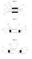
- FIG. 1 represents a device 10 according to the invention comprising an optical fiber 11 comprising a core 12 surrounded by an optical sheath 13.
- the core 12, of refractive index n 12 consists of a material comprising a compound mixture 80% by weight of O ', O'-bis (2-aminopropyl) polyethylene glycol 1900 (sold under the brand "JEFFAMINE” by the company HUNTSMAN) and 20% by weight of ethylene glycol diglycidyl ether (supplied by ALDRICH), in which a salt is added which is sodium iodide Nal at a concentration of 1 M, and a crosslinking catalyst which is lithium perchlorate LiClO 4 at a concentration of 0.1 M.
- the optical sheath 13, having a refractive index n 13 of less than n 12 is made of a material similar to that of the core in which a fluorinated additive has been added in order to reduce the refractive index.
- the device 10 also comprises a first electrode 14 and a second electrode 15 arranged on either side of the optical fiber 11 .
- the electrodes 14 and 15 are in ionic contact with the core 12 by means of the sheath 13, itself ionic conductor.
- the two electrodes 14 and 15 are identical and made up of a mixture comprising 50% by weight of BRX activated carbon manufactured by the company NORIT and 50% by weight of the material constituting the core 12 .
- the device 20 comprises a plane waveguide comprising a guiding layer 21, having a refractive index n 21 , made of a material similar to that of the core 12 of FIG. 1 , but in which a sulfur additive has been added in order to increase the refractive index.
- the guide layer 21 is surrounded by a sheath 22, having a refractive index n 22 less than n 21 , made of a material similar to that of the core 12 of FIG. 1.
- the guide layer 21, surrounded by the sheath 22 is deposited on a substrate 23 which is preferably made of silicon Si or of indium phosphoride InP.
- the device 20 further comprises a first electrode 24 and a second electrode 25 arranged on either side of the waveguide and in physical contact with the guiding layer 21 : they are thus in ionic contact with the guiding layer 21.
- the two electrodes 24 and 25 are identical and made of a material similar to that of the electrodes 14 and 15 of FIG. 1.
- a voltage of 2.2 volts is applied between the two electrodes 24 and 25 in order to cause a variation in the index n 21 of the guiding layer 21 of the waveguide.
- a variation ⁇ n 21 5.10 -2 is obtained.
- the capacity of the device 20 is 0.02 Farad.
- the sheath 22 is also made of an ion-conducting material. By diffusion, a variation of the refractive index n 22 of the sheath 22 occurs simultaneously .
- FIG. 3 shows another device 30 according to the invention comprising a plane waveguide comprising a guiding layer 31, having a refractive index n 31 , surrounded by a sheath 32, having a refractive index n 32 less than n 31 , made of a material similar to that of the optical sheath 13 of FIG. 1.
- the guiding layer made of a material similar to that of the core 12 of FIG. 1 but not containing Nal salt (sodium iodide ), is not an ionic conductor.
- the guiding layer could also be made of silica.
- the waveguide is deposited on a substrate 33 similar to that of FIG. 2.
- the device 30 further comprises a first electrode 34 and a second electrode 35 arranged in the sheath 32 on either side of the guiding part 31 , but which are not in physical contact with the guiding part 31 .
- the material constituting the sheath 32 being ionic conductor, the electrodes 34 and 35 are thus in ionic contact with the guiding layer 31 via the sheath 32.
- the two electrodes 34 and 35 are identical and made of a similar material to that of the electrodes 14 and 15 of FIG. 1.
- a voltage of 2.2 Volts is applied between the two electrodes 34 and 35 in order to cause a variation in the index n 32 of the sheath 32 of the waveguide.
- a variation ⁇ n 32 5.10 -2 is obtained.
- the capacity of the device 30 is 0.02 Farad.
- a plane waveguide comprising a guiding layer 41, having a refractive index n 41 , made of a material similar to that of the core 12 of FIG. 1.
- the layer guide 41 is surrounded by a sheath 42, having a refractive index n 42 less than n 41 , made of a material similar to that of the optical sheath 13 of FIG. 1.
- the waveguide is deposited on a substrate 43 similar to that of FIG. 2.
- the device 40 further comprises a first electrode 44 and a second electrode 45 arranged on the same side and in physical contact with the guiding layer 41 : they are thus in ionic contact with the guiding layer 41.
- the electrode 44 consists of a mixture comprising 50% by weight of polythiophene and 50% by weight of the material constituting the core 12 of FIG. 1.
- the electrode 45 consists of a mixture comprising 50% by weight of polypyrrole and 50% by weight of the ma constituent material of the heart 12 of FIG. 1.
- a plane waveguide similar to that of Figure 4 comprising a guide layer 51, having a refractive index n 51 , surrounded by a sheath 52, having an index of refraction n 52 less than n 51 .
- the waveguide is deposited on a substrate 53 similar to that of FIG. 2.
- the device 50 further comprises a first electrode 54 and a second electrode 55 arranged in the sheath 52 , on the same side of the guiding layer 51 and in ionic contact with it via the ionic conductive material of the sheath 52 .
- the electrodes 54 and 55 are identical and made of a material similar to those of FIG. 4.
- FIG. 6 shows another device 60 according to the invention comprising a plane waveguide comprising a guiding layer 61 having a refractive index n 61 , made of a material similar to that of the core 12 of FIG. 1 in which a sulfur additive was added to increase the refractive index.
- the guiding layer 61 is surrounded by a sheath 62 having a refractive index n 33 less than n 31 , made of a material similar to that of the core 12 of FIG. 1.
- the waveguide is deposited on a substrate 63 similar to that of FIG. 2.
- the device 60 further comprises a first electrode 64 and a second electrode 65 arranged in the sheath 62 , on the same side with respect to the guiding layer 61 and in ionic contact with it via the sheath 62 , itself an ionic conductor.
- the electrode 64 consists of a mixture comprising 50% by weight of polythiophene and 50% by weight of the material constituting the core 12 of FIG. 1.
- the electrode 65 consists of a mixture comprising 50% by weight of polypyrrole and 50% by weight of the material constituting the core 12 of FIG. 1.
- a waveguide comprises a guiding layer 72, having a refractive index n 72 , is surrounded by an optical cladding 73 having a refractive index n 73 less than n 72 .
- the guiding layer 72 made of silica is not ionic conductive.
- the optical sheath 73 is made of a material similar to that of the optical sheath 13 of FIG. 1.
- the device 70 further comprises a first electrode 74 and a second electrode 75 arranged in the optical sheath 73 on either side of the guiding layer 71. The electrodes 74 and 75 are thus in ionic contact with the sheath 73, itself ionic conductor.
- the electrodes 74 and 75 are identical and made of a material similar to that of the electrodes 14 and 15 of FIG. 1.
- a portion of the guiding layer 72 of the fiber 71 is used as an adjustable filter.
- a Bragg grating 76 has been formed there which consists of a periodic variation of amplitude ⁇ n 72 of the refractive index of layer 72 around its mean value n 72 with a spatial period ⁇ (not of the grating) along the axis of propagation of the wave.
- the Bragg grating can also be obtained by varying the index ⁇ n 73 of the cladding 73 around its average value n 73 .
- n eff represents a characteristic quantity of the filter which is a function of n 72 and n 73 . This is the reason why we can obtain a variation of n eff by varying either n 72 , n 73 , or even both at the same time.
- n eff depends on the respective indices of the salt and of the polymer constituting the ion conductor: if the salt has an index higher than that of the polymer, the output of the salt will cause the index of the heart and vice versa.
- a waveguide comprising a Bragg grating can be produced not only with an optical fiber but also by using any other type of waveguide, in particular the plane waveguides of the integrated optics.
- a Bragg grating can be in the guiding part in silica by a known optical, mechanical or chemical process causing a physical modification of the support. It is possible to register a Bragg grating in a polymer, in particular under the effect of irradiation.
- a waveguide comprises a guiding layer 82, having a refractive index n 72 , is surrounded by an optical cladding 83 having a refractive index n 73 less than n 72 .
- the guiding layer 82 is made of a material similar to that of the core 12 of Figure 1.
- the optical sheath 83 is made of a material similar to that of the optical sheath 13 of Figure 1.
- the device 80 further comprises a first electrode 84 and a second electrode 85 arranged on the same side and in physical contact with the guiding layer 82 : they are thus in ionic contact with the guiding layer 82.
- the electrodes 84 and 85 are identical and made of a material similar to that of the electrodes 14 and 15 of FIG. 1.
Landscapes
- Physics & Mathematics (AREA)
- Nonlinear Science (AREA)
- General Physics & Mathematics (AREA)
- Optics & Photonics (AREA)
- Optical Integrated Circuits (AREA)
- Optical Modulation, Optical Deflection, Nonlinear Optics, Optical Demodulation, Optical Logic Elements (AREA)
- Glass Compositions (AREA)
- Electrochromic Elements, Electrophoresis, Or Variable Reflection Or Absorption Elements (AREA)
- Surface Treatment Of Glass (AREA)
- Optical Fibers, Optical Fiber Cores, And Optical Fiber Bundles (AREA)
Abstract
Description
On peut citer par exemple un interféromètre à deux guides, de type MACH-ZEHNDER ou MICHELSON, qui est utilisé pour obtenir notamment un filtre accordable ou un modulateur. Dans ce cas on fait varier l'indice de réfraction dans l'un des deux guides afin de modifier la transmission de l'interféromètre.
Le filtre FABRY-PERROT est un interféromètre à ondes multiples dans lequel un changement d'indice provoque un décalage des fréquences de résonance et qui peut être utilisé pour obtenir un filtre accordable. Un laser accordable est un autre cas particulier de ce type de filtre où la longueur optique de la cavité peut être ajustée afin de contrôler très précisément la longueur d'onde d'émission. Pour cela on dispose dans la cavité une section de phase qui est un guide d'onde dont l'indice est modifiable.
On peut encore citer les multiplexeurs/démultiplexeurs à réseau de guides, parfois appelés "phasar" ou "AWG". La possibilité de modifier l'indice de réfraction des guides peut être utilisée pour accorder la réponse spectrale du composant.
Bien entendu, on peut aussi modifier l'indice d'un guide simple ne faisant pas partie d'un système interférométrique. Par exemple dans une jonction, il peut être important de modifier l'indice de réfraction d'un guide par rapport à un autre. Par exemple dans une jonction en Y, en changeant l'indice de l'un des deux bras de sortie, on va diriger le signal d'entrée vers l'une ou l'autre sortie. On a ainsi formé un commutateur ("digital optical switch"). Le besoin de tels systèmes est très important pour toutes les applications de commutation.
La capacité des électrodes décrites est très faible car l'accumulation des ions ne s'effectue que sur leur surface. De ce fait dès que la tension ne sera plus maintenue, la variation d'indice interfacial va rapidement disparaítre par autodécharge. En outre la modification de l'indice de réfraction ainsi obtenue est limitée à l'interface de contact entre le conducteur d'ions et les électrodes. La modification est de ce fait difficilement réversible et entraíne un phénomène de vieillissement. Enfin ce dispositif est d'utilisation peu aisée. Il a pour inconvénient de nécessiter le maintien permanent des électrodes sous une tension relativement élevée (20V) pour conserver l'indice de réfraction souhaité, ce qui conduit à une consommation de courant électrique non négligeable.
Selon une première variante, les électrodes contiennent comme matière électrochimiquement active un charbon actif. De préférence on utilise un charbon actif ayant une surface spécifique supérieure à 200m2/g. Ces électrodes sont aussi appelées électrodes "bloquantes" car elles stockent les ions selon le principe de la double couche électrochimique de Helmotz. La quantité d'ions susceptible d'être stockée est proportionnelle à la surface spécifique du matériau. Dans ce cas la quantité Q d'ions absorbés par les électrodes est proportionnelle à la tension V appliquée entre les deux électrodes selon la relation : Q = C x V dans laquelle C est la capacité des électrodes à absorber et désorber des ions, exprimée en Farad.
Selon une deuxième variante, une première électrode contient comme matière électrochimiquement active un matériau apte à insérer des cations dans sa structure et une seconde électrode contient comme matière électrochimiquement active un matériau d'insertion apte à insérer des anions dans sa structure. De préférence le matériau apte à insérer des cations dans sa structure est choisi parmi un oxyde de métaux de transition, un sulfure, un sulfate et leurs mélanges. Et de préférence encore le matériau apte à insérer des anions dans sa structure est choisi parmi un oxyde graphitique, un graphite, un coke, un noir de carbone et un carbone vitreux. Parmi les oxydes de métaux de transition utilisables dans la présente invention, on peut citer l'oxyde de vanadium, les oxydes lithiés de manganèse, de nickel et/ou de cobalt, et leurs mélanges.
Selon une troisième variante, les électrodes contiennent comme matière électrochimiquement active un polymère conducteur. De préférence, le polymère conducteur est choisi parmi un polypyrrole, un polythiophène, une polyaniline, un polyacéthylène et un polyparaphénylène. La plupart de ces matériaux peuvent être dopés N ou P. Un matériau dopé P absorbera les anions (ion chargé négativement) et un matériau dopé N absorbera les cations (ion chargé positivement).
Il est bien entendu possible de combiner entre elles les électrodes correspondant aux trois variantes précédemment décrites.
Dans la présente invention les électrodes sont des électrodes volumiques, c'est à dire que la totalité de leur volume est impliquée dans la réaction électrochimique. Elles possèdent donc une capacité élevée. De ce fait dès que la tension ne sera plus maintenue, l'effet mémoire jouera de manière importante et la variation d'indice obtenu ne variera quasiment pas. Cependant pour conserver l'indice de réfraction à la valeur précise choisie, il est préférable de maintenir le potentiel appliqué. Ainsi toute dérive est évitée pour une consommation énergétique pratiquement nulle, car très inférieure à 1µA.
De préférence le matériau constituant le conducteur d'ions est choisi parmi un polymère contenant un sel dissocié et un polymère contenant un sel dissout dans un solvant.
On entend par polymère contenant un sel dissocié, un polymère qui complexe un sel ionisable. Dans ce cas le polymère joue un rôle actif vis à vis du sel car il contribue à sa dissociation et à la solvatation des ions. On le nomme aussi polymère sec car il ne contient pas de solvant. On peut choisir comme polymère contenant un sel dissocié, un polyéther ou un polyoxyéthylène.
On entend par polymère contenant un sel dissout dans un solvant, un polymère gonflé par un solvant qui contient un sel dissocié. Le polymère est dit alors gélifié ou plastifié, et la solution liquide de sel est souvent appelé plastifiant. Dans ce cas, le polymère joue un rôle passif vis à vis du sel car il ne contribue que de manière négligeable à sa dissociation et à la solvatation des ions. On peut choisir comme polymère contenant un sel dissout dans un solvant : un polymère thermoplastique, un homopolymère fluoré ou un copolymère fluoré. Dans le cas où le polymère contenant un sel dissout dans un solvant est un polymère thermoplastique, il est choisi de préférence parmi un polyacrylonitrile, un polyméthacrylate de méthyle, un polychlorure de vinyle et leurs copolymères.
Selon une variante, la partie guidante et la partie gainante sont conducteur ionique. Dans ce cas, la variation d'indice affectera aussi bien la partie guidante que la partie gainante.
Selon une autre variante, la partie guidante est conducteur ionique et la partie gainante n'est pas conducteur ionique. Dans ce cas, la variation d'indice affectera seulement la partie guidante.
Selon une variante, la partie guidante et la partie gainante sont conducteur ionique. Les électrodes sont alors en contact ionique avec la partie guidante par l'intermédiaire de la partie gainante. Lors de l'application d'une tension entre les électrodes, la variation de concentration du sel se propage par diffusion dans tout le volume de la partie gainante et de la partie guidante. Compte-tenu des très faibles dimensions d'une fibre optique ou d'un guide d'onde, cette diffusion s'effectue quasi-instantanément.
Selon une autre variante, la partie guidante n'est pas conducteur ionique et la partie gainante est conducteur ionique. Les électrodes sont alors en contact ionique seulement avec la partie gainante. Dans ce cas la variation de concentration du sel, et donc la variation d'indice de réfraction, ne se produit que dans la partie gainante, ce qui résulte en une modification de l'indice de réfraction effectif moyen neff du guide d'onde.
Selon un quatrième mode de réalisation, les électrodes sont respectivement disposées du même côté de ladite partie guidante. Lors de l'application d'une tension entre les électrodes, la variation de concentration du sel se propagera par diffusion dans tout le volume de la partie gainante et de la partie guidante quelle que soit la position relative des électrodes.
Selon une deuxième forme d'exécution, le guide d'onde est un guide d'onde plan, déposé sur un substrat, comprenant une couche guidante, constituant la partie guidante, entourée d'une gaine, constituant la partie gainante. Le guide d'onde peut en outre être entouré d'un superstrat.
Bien entendu les fibres optiques et les guides d'ondes auxquels s'applique l'invention peuvent être fabriqués en employant tout procédé connu.
L'invention est plus particulièrement destinée à être utilisée avec des guides d'onde de type "monomode".
- on dispose les électrodes en contact ionique avec le conducteur ayant un indice de réfraction initial,
- on applique une tension inférieure à 20 Volts entre les électrodes de manière à provoquer la variation de l'indice initial,
- on obtient ledit conducteur ionique avec un indice de réfraction modifié,
- on supprime la tension appliquée, et ledit indice de réfraction modifié est maintenu.
La gaine optique 13, ayant un indice de réfraction n13 inférieur à n12, est constituée d'un matériau analogue à celui du coeur dans lequel un additif fluoré a été ajouté afin d'en diminuer l'indice de réfraction. Le dispositif 10 comporte en outre une première électrode 14 et une seconde électrode 15 disposées de part et d'autre de la fibre optique 11. Les électrodes 14 et 15 sont en contact ionique avec le coeur 12 par l'intermédiaire de la gaine 13, elle-même conducteur ionique. Les deux électrodes 14 et 15 sont identiques et constituées d'un mélange comprenant 50% en poids de charbon actif BRX fabriqué par la société NORIT et de 50% en poids du matériau constitutif du coeur 12.
On applique entre les deux électrodes 24 et 25 une tension de 2,2 Volts afin de provoquer une variation de l'indice n21 de la couche guidante 21 du guide d'onde. On obtient une variation Δn21 = 5.10-2. La capacité du dispositif 20 est de 0,02 Farad. Une fois obtenue la variation d'indice Δn21, si on souhaite maintenir la tension entre les électrodes 24 et 25, on observe un courant qui est très inférieure à 1µA. Si on supprime la tension imposée, la variation d'indice se maintient au moins pendant plusieurs heures. Le retour à l'état initial s'effectue ensuite très lentement. Dans le cas présent, la gaine 22 est également constituée d'un matériau conducteur d'ions. Par diffusion, il se produit simultanément une variation de l'indice de réfraction n22 de la gaine 22.
Une portion de la couche guidante 72 de la fibre 71 est utilisée comme filtre ajustable. On y a formé un réseau de Bragg 76 qui consiste en une variation périodique d'amplitude Δn72 de l'indice de réfraction de la couche 72 autour de sa valeur moyenne n72 avec une période spatiale Λ (pas du réseau) le long de l'axe de propagation de l'onde. Le réseau de Bragg peut aussi être obtenu par une variation de l'indice Δn73 de la gaine 73 autour de sa valeur moyenne n73. Si on applique une tension U, par exemple de 3 Volts, entre les électrodes 74 et 75, la variation de l'indice effectif moyen du guide neff induite par cette tension engendre une variation de la longueur d'onde centrale λb du filtre, au travers de la relation :
Bien entendu un guide d'onde comportant un réseau de Bragg peut être réalisé non seulement avec une fibre optique mais aussi en utilisant n'importe quel autre type de guide d'onde, notamment les guides d'onde plans de l'optique intégrée.
Dans le cas présent, un réseau de Bragg peut être dans la partie guidante en silice par un procédé connu optique, mécanique ou chimique entraínant une modification physique du support. On peut réaliser l'inscription d'un réseau de Bragg dans un polymère notamment sous l'effet d'une irradiation. Il suffit pour cela que le polymère soit photosensible. L'utilisation d'un procédé holographique a aussi été mentionné (B. L. Booth et al. : "Polyguide™ Polymeric Technology For Optical Interconnect Circuits And Components", SPIE 1997).
Les réseaux de Bragg sont particulièrement utilisés dans les dispositifs destinés aux applications WDM (multiplexage en longueur d'onde).
Claims (30)
- Dispositif optique comprenant un conducteur d'ions constitué d'une matière transparente à la lumière contenant des ions mobiles et au moins une paire d'électrodes, l'indice de réfraction dans au moins une zone dudit conducteur d'ions étant susceptible de varier sous l'effet de la tension appliquée entre lesdites électrodes, caractérisé en ce que lesdites électrodes sont aptes à absorber et désorber des ions et sont en contact ionique avec ledit conducteur d'ions.
- Dispositif selon la revendication 1, dans lequel chacune desdites électrodes contiennent une matière électrochimiquement active choisie parmi un charbon actif, un polymère conducteur et un matériau d'insertion apte à insérer des ions dans sa structure.
- Dispositif selon la revendication 1, dans lequel lesdites électrodes contiennent comme matière électrochimiquement active un charbon actif.
- Dispositif selon la revendication 3, dans lequel ledit charbon actif a une surface spécifique supérieure à 200m2/g.
- Dispositif selon la revendication 1, dans lequel la première desdites électrodes contient comme matière électrochimiquement active un matériau apte à insérer des cations dans sa structure et la seconde desdites électrodes contient comme matière électrochimiquement active un matériau d'insertion apte à insérer des anions dans sa structure.
- Dispositif selon la revendication 5, dans lequel ledit matériau apte à insérer des cations dans sa structure est choisi parmi un oxyde de métaux de transition, un sulfure, un sulfate et leurs mélanges.
- Dispositif selon la revendication 5, dans lequel ledit matériau apte à insérer des anions dans sa structure est choisi parmi un oxyde graphitique, un graphite, un coke, un noir de carbone et un carbone vitreux.
- Dispositif selon la revendication 1, dans lequel lesdites électrodes contiennent comme matière électrochimiquement active un polymère conducteur.
- Dispositif selon la revendication 8, dans lequel ledit polymère conducteur est choisi parmi un polypyrrole, un polythiophène, une polyaniline, un polyacéthylène et un polyparaphénylène.
- Dispositif selon l'une des revendications précédentes, dans lequel ledit conducteur d'ions contient des ions mobiles comprenant au moins un cation choisi parmi Li+, Na+, K+, Ca2+ et NH4 + et au moins un anion choisi parmi CF3SO3 -, N(CF3SO2)2 -, N(C2F5SO2)2 -, C(CF3SO2)3 -, CF3CO3 -, ClO4 -, BF4 -, AsF6 -, PF6 -, BH4 -, SCN-, N3 -, I- et Br-.
- Dispositif selon la revendication 10, dans lequel le matériau constituant ladite partie guidante est choisi parmi un polymère contenant un sel dissocié et un polymère contenant un sel dissout dans un solvant.
- Dispositif selon la revendication 11, dans lequel ledit polymère contenant un sel dissout est choisi parmi un polyéther et un polyoxyéthylène,
- Dispositif selon la revendication 11, dans lequel ledit polymère contenant un sel dissout dans un solvant est choisi parmi un polymère thermoplastique, un homopolymère fluoré et un copolymère fluoré.
- Dispositif selon la revendication 13, dans lequel ledit polymère contenant un sel dissout dans un solvant est un polymère thermoplastique choisi parmi un polyacrylonitrile, un polyméthacrylate de méthyle, un polychlorure de vinyle et leurs copolymères.
- Dispositif selon l'une des revendications 11 à 14, dans lequel ledit sel est choisi parmi le perchlorate de lithium, l'hexafluoroarsénate de lithium, l'hexafluorophosphate de lithium, le tétrafluoroborate de lithium, le trifluorométhanesulfonate de lithium, le trifluorométhanesulfonimide de lithium, le trifluorométhanesulfoneméthide de lithium, le bis(perfluoroéthylsulfonimide) de lithium et le chlorure de tétralkylammonium.
- Dispositif selon l'une des revendications précédentes, dans lequel ledit conducteur d'ions est inclu dans un guide d'onde comprenant une partie guidante et une partie gainante.
- Dispositif selon la revendication 16, dans lequel lesdites électrodes sont disposées au contact physique de ladite partie guidante.
- Dispositif selon la revendication 17, dans lequel ladite partie guidante et ladite partie gainante sont conducteur ionique.
- Dispositif selon la revendication 17, dans lequel ladite partie guidante est conducteur ionique et ladite partie gainante n'est pas conducteur ionique.
- Dispositif selon la revendication 16, dans lequel lesdites électrodes sont disposées au contact physique de ladite partie gainante.
- Dispositif selon la revendication 20, dans lequel ladite partie guidante et ladite partie gainante sont conducteur ionique.
- Dispositif selon la revendication 20, dans lequel ladite partie guidante n'est pas conducteur ionique et ladite partie gainante est conducteur ionique.
- Dispositif selon la revendication 16, dans lequel lesdites électrodes sont respectivement disposées de part et d'autre de ladite partie guidante.
- Dispositif selon la revendication 16, dans lequel lesdites électrodes sont respectivement disposées du même côté de ladite partie guidante.
- Dispositif selon l'une des revendications 16 à 24, dans lequel ledit guide d'onde est une fibre optique.
- Dispositif selon l'une des revendications 16 à 24, dans lequel ledit guide d'onde est un guide d'onde plan.
- Dispositif selon l'une des revendications 16 à 26, dans lequel ladite partie guidante comprend un réseau de Bragg.
- Procédé pour modifier l'indice de réfraction d'un conducteur d'ions, constitué d'une matière transparente à la lumière contenant des ions mobiles, au moyen d'au moins une paire d'électrodes, caractérisé en ce qu'il comporte les étapes suivantes :on dispose lesdites électrodes en contact ionique avec ledit conducteur ayant un indice de réfraction initial,on applique une tension inférieure à 20 Volts entre lesdites électrodes de manière à provoquer la variation dudit indice initial,on obtient ledit conducteur ionique avec un indice de réfraction modifié,on supprime la tension appliquée, et ledit indice de réfraction modifié est maintenu.
- Procédé selon la revendication 28, dans lequel ladite tension est au plus égale à 5 Volts.
- Procédé selon l'une des revendications 23 et 24, dans lequel ladite tension est appliquée pendant une durée comprise entre 10 et 100 millisecondes.
Applications Claiming Priority (2)
| Application Number | Priority Date | Filing Date | Title |
|---|---|---|---|
| FR0300028 | 2003-01-03 | ||
| FR0300028A FR2849700B1 (fr) | 2003-01-03 | 2003-01-03 | Dispositif optique a indice de refraction variable |
Publications (2)
| Publication Number | Publication Date |
|---|---|
| EP1435540A1 true EP1435540A1 (fr) | 2004-07-07 |
| EP1435540B1 EP1435540B1 (fr) | 2006-08-09 |
Family
ID=32480355
Family Applications (1)
| Application Number | Title | Priority Date | Filing Date |
|---|---|---|---|
| EP03293178A Expired - Lifetime EP1435540B1 (fr) | 2003-01-03 | 2003-12-16 | Dispositif optique à indice de réfraction variable comprenant un conducteur d'ions |
Country Status (6)
| Country | Link |
|---|---|
| US (1) | US6980719B2 (fr) |
| EP (1) | EP1435540B1 (fr) |
| JP (1) | JP2004212993A (fr) |
| AT (1) | ATE336024T1 (fr) |
| DE (1) | DE60307410D1 (fr) |
| FR (1) | FR2849700B1 (fr) |
Families Citing this family (6)
| Publication number | Priority date | Publication date | Assignee | Title |
|---|---|---|---|---|
| WO2004113441A1 (fr) * | 2003-06-18 | 2004-12-29 | Shin-Etsu Polymer Co., Ltd. | Composition conductrice, enduit conducteur, resine conductrice, condensateur, element convertisseur photo-electrique et procede de production associe |
| KR101603778B1 (ko) * | 2009-01-19 | 2016-03-25 | 삼성전자주식회사 | 광 이미지 셔터 |
| JP2023007522A (ja) * | 2019-12-24 | 2023-01-19 | パナソニックIpマネジメント株式会社 | 光デバイス |
| CN111180895B (zh) * | 2020-01-16 | 2021-03-30 | 电子科技大学 | 一种具有高选通性的可调谐吸透一体材料 |
| CN116266018A (zh) * | 2022-07-17 | 2023-06-20 | 上海图灵智算量子科技有限公司 | 电光调制器及光计算网络 |
| CN115356288B (zh) * | 2022-08-05 | 2025-05-27 | 山东大学 | 基于原位生长聚合物的微纳光纤气体传感器及制备方法 |
Citations (5)
| Publication number | Priority date | Publication date | Assignee | Title |
|---|---|---|---|---|
| CH627860A5 (en) * | 1979-07-31 | 1982-01-29 | Hoffmann La Roche | Electrooptical cell |
| EP0496278A2 (fr) * | 1991-01-16 | 1992-07-29 | Hamamatsu Photonics K.K. | Dispositif optique et appareil l'utilisant |
| EP1081538A2 (fr) * | 1999-09-03 | 2001-03-07 | Agilent Technologies Inc | Elément optique à indice de réfraction électrocommandable |
| US20010019800A1 (en) * | 1998-12-10 | 2001-09-06 | Sylvie Herreyre | A rechargeable lithium electrochemical cell usable at low temperature |
| EP1298469A2 (fr) * | 2001-09-27 | 2003-04-02 | Alcatel | Filtre accordable composé d'une fibre optique avec un réseau de Bragg |
Family Cites Families (4)
| Publication number | Priority date | Publication date | Assignee | Title |
|---|---|---|---|---|
| JPS55500789A (fr) * | 1978-10-18 | 1980-10-16 | ||
| US5724177A (en) * | 1991-09-04 | 1998-03-03 | Sun Active Glass Electrochromics, Inc. | Electrochromic devices and methods |
| US6625378B2 (en) * | 1999-02-01 | 2003-09-23 | Jds Uniphase Corporation | Variable optical attenuator device |
| US6914802B2 (en) * | 2000-02-11 | 2005-07-05 | Axon Technologies Corporation | Microelectronic photonic structure and device and method of forming the same |
-
2003
- 2003-01-03 FR FR0300028A patent/FR2849700B1/fr not_active Expired - Fee Related
- 2003-12-16 DE DE60307410T patent/DE60307410D1/de not_active Expired - Lifetime
- 2003-12-16 AT AT03293178T patent/ATE336024T1/de not_active IP Right Cessation
- 2003-12-16 EP EP03293178A patent/EP1435540B1/fr not_active Expired - Lifetime
- 2003-12-22 US US10/740,760 patent/US6980719B2/en not_active Expired - Fee Related
- 2003-12-25 JP JP2003429369A patent/JP2004212993A/ja not_active Withdrawn
Patent Citations (5)
| Publication number | Priority date | Publication date | Assignee | Title |
|---|---|---|---|---|
| CH627860A5 (en) * | 1979-07-31 | 1982-01-29 | Hoffmann La Roche | Electrooptical cell |
| EP0496278A2 (fr) * | 1991-01-16 | 1992-07-29 | Hamamatsu Photonics K.K. | Dispositif optique et appareil l'utilisant |
| US20010019800A1 (en) * | 1998-12-10 | 2001-09-06 | Sylvie Herreyre | A rechargeable lithium electrochemical cell usable at low temperature |
| EP1081538A2 (fr) * | 1999-09-03 | 2001-03-07 | Agilent Technologies Inc | Elément optique à indice de réfraction électrocommandable |
| EP1298469A2 (fr) * | 2001-09-27 | 2003-04-02 | Alcatel | Filtre accordable composé d'une fibre optique avec un réseau de Bragg |
Also Published As
| Publication number | Publication date |
|---|---|
| EP1435540B1 (fr) | 2006-08-09 |
| FR2849700B1 (fr) | 2005-04-29 |
| US20040131314A1 (en) | 2004-07-08 |
| US6980719B2 (en) | 2005-12-27 |
| ATE336024T1 (de) | 2006-09-15 |
| JP2004212993A (ja) | 2004-07-29 |
| DE60307410D1 (de) | 2006-09-21 |
| FR2849700A1 (fr) | 2004-07-09 |
Similar Documents
| Publication | Publication Date | Title |
|---|---|---|
| EP0141714B1 (fr) | Modulateur optique | |
| Rabus | Integrated ring resonators: the compendium | |
| EP3009879B1 (fr) | Modulateur de phase électro-optique et procédé de modulation | |
| EP3009878B1 (fr) | Modulateur de phase électro-optique | |
| EP0451047A1 (fr) | Composant optique intégré protégé contre l'environnement et son procédé de fabrication | |
| EP0473496B1 (fr) | Procédé de fabrication d'un guide d'onde optique monomode en polymère doué de propriétés électrooptiques, ainsi qu'un tel guide d'onde optique | |
| EP0544596B1 (fr) | Procédé de fabrication d'un guide onde optique ruban entièrement à base de polymères | |
| EP0762576B1 (fr) | Composant opto-électronique intégré | |
| EP1235318A1 (fr) | Laser accordable de façon rapide et large | |
| EP1435540B1 (fr) | Dispositif optique à indice de réfraction variable comprenant un conducteur d'ions | |
| CN1922533A (zh) | 用于在具有光子晶体晶格的光学器件中调制光束的方法和装置 | |
| FR2970788A1 (fr) | Circuit electro-optique en structure micro-massive a base de matériaux electro-optiques a coefficient géant, et procédé de fabrication | |
| Kato et al. | Switching operation in tunable add-drop multiplexer with si-grating waveguides featuring ferroelectric liquid crystal cladding | |
| FR2601505A1 (fr) | Dispositif semiconducteur integre du type dispositif de couplage entre un photodetecteur et un guide d'onde lumineuse | |
| EP0999622A1 (fr) | Amplificateur optique à semi-conducteur à gain stabilisé réglable et système optique utilisant un tel amplificateur | |
| FR2708351A1 (fr) | Dispositif optique accordable. | |
| CN1781054A (zh) | 用于在光学器件中相移光束的方法和设备 | |
| EP0433109B1 (fr) | Dispositif permettant d'accorder de façon continue une source de lumière cohérente et polarisée rectilignement | |
| Barusseau | cio, Patent Application Publication (io) Pub. No.: US 2004/0131314A1 | |
| Rabus et al. | Devices | |
| FR2820827A1 (fr) | Dispositif d'attenuation d'un signal vehicule par fibre optique sous la forme d'un faisceau lumineux, systeme d'attenuation et applications correspondantes | |
| Wang et al. | Electronically tunable external-cavity laser diode using a liquid crystal deflector | |
| Agranat et al. | The electroholographic optical switches and interconnects | |
| FR2725048A1 (fr) | Dispositif de modulation de phase utilisant l'effet electroclinique dans un cristal liquide en phase chirale smectique a* | |
| Wang et al. | Electrically tunable free-space sub-wavelength grating filters with 30nm tuning range |
Legal Events
| Date | Code | Title | Description |
|---|---|---|---|
| PUAI | Public reference made under article 153(3) epc to a published international application that has entered the european phase |
Free format text: ORIGINAL CODE: 0009012 |
|
| AK | Designated contracting states |
Kind code of ref document: A1 Designated state(s): AT BE BG CH CY CZ DE DK EE ES FI FR GB GR HU IE IT LI LU MC NL PT RO SE SI SK TR |
|
| AX | Request for extension of the european patent |
Extension state: AL LT LV MK |
|
| 17P | Request for examination filed |
Effective date: 20041216 |
|
| AKX | Designation fees paid |
Designated state(s): AT BE BG CH CY CZ DE DK EE ES FI FR GB GR HU IE IT LI LU MC NL PT RO SE SI SK TR |
|
| 17Q | First examination report despatched |
Effective date: 20050510 |
|
| GRAP | Despatch of communication of intention to grant a patent |
Free format text: ORIGINAL CODE: EPIDOSNIGR1 |
|
| GRAS | Grant fee paid |
Free format text: ORIGINAL CODE: EPIDOSNIGR3 |
|
| GRAA | (expected) grant |
Free format text: ORIGINAL CODE: 0009210 |
|
| AK | Designated contracting states |
Kind code of ref document: B1 Designated state(s): AT BE BG CH CY CZ DE DK EE ES FI FR GB GR HU IE IT LI LU MC NL PT RO SE SI SK TR |
|
| PG25 | Lapsed in a contracting state [announced via postgrant information from national office to epo] |
Ref country code: IT Free format text: LAPSE BECAUSE OF FAILURE TO SUBMIT A TRANSLATION OF THE DESCRIPTION OR TO PAY THE FEE WITHIN THE PRESCRIBED TIME-LIMIT;WARNING: LAPSES OF ITALIAN PATENTS WITH EFFECTIVE DATE BEFORE 2007 MAY HAVE OCCURRED AT ANY TIME BEFORE 2007. THE CORRECT EFFECTIVE DATE MAY BE DIFFERENT FROM THE ONE RECORDED. Effective date: 20060809 Ref country code: SI Free format text: LAPSE BECAUSE OF FAILURE TO SUBMIT A TRANSLATION OF THE DESCRIPTION OR TO PAY THE FEE WITHIN THE PRESCRIBED TIME-LIMIT Effective date: 20060809 Ref country code: FI Free format text: LAPSE BECAUSE OF FAILURE TO SUBMIT A TRANSLATION OF THE DESCRIPTION OR TO PAY THE FEE WITHIN THE PRESCRIBED TIME-LIMIT Effective date: 20060809 Ref country code: RO Free format text: LAPSE BECAUSE OF FAILURE TO SUBMIT A TRANSLATION OF THE DESCRIPTION OR TO PAY THE FEE WITHIN THE PRESCRIBED TIME-LIMIT Effective date: 20060809 Ref country code: AT Free format text: LAPSE BECAUSE OF FAILURE TO SUBMIT A TRANSLATION OF THE DESCRIPTION OR TO PAY THE FEE WITHIN THE PRESCRIBED TIME-LIMIT Effective date: 20060809 Ref country code: SK Free format text: LAPSE BECAUSE OF FAILURE TO SUBMIT A TRANSLATION OF THE DESCRIPTION OR TO PAY THE FEE WITHIN THE PRESCRIBED TIME-LIMIT Effective date: 20060809 Ref country code: IE Free format text: LAPSE BECAUSE OF FAILURE TO SUBMIT A TRANSLATION OF THE DESCRIPTION OR TO PAY THE FEE WITHIN THE PRESCRIBED TIME-LIMIT Effective date: 20060809 Ref country code: GB Free format text: LAPSE BECAUSE OF FAILURE TO SUBMIT A TRANSLATION OF THE DESCRIPTION OR TO PAY THE FEE WITHIN THE PRESCRIBED TIME-LIMIT Effective date: 20060809 Ref country code: NL Free format text: LAPSE BECAUSE OF FAILURE TO SUBMIT A TRANSLATION OF THE DESCRIPTION OR TO PAY THE FEE WITHIN THE PRESCRIBED TIME-LIMIT Effective date: 20060809 Ref country code: CZ Free format text: LAPSE BECAUSE OF FAILURE TO SUBMIT A TRANSLATION OF THE DESCRIPTION OR TO PAY THE FEE WITHIN THE PRESCRIBED TIME-LIMIT Effective date: 20060809 |
|
| REG | Reference to a national code |
Ref country code: GB Ref legal event code: FG4D Free format text: NOT ENGLISH |
|
| REG | Reference to a national code |
Ref country code: CH Ref legal event code: EP |
|
| REG | Reference to a national code |
Ref country code: IE Ref legal event code: FG4D Free format text: LANGUAGE OF EP DOCUMENT: FRENCH |
|
| REF | Corresponds to: |
Ref document number: 60307410 Country of ref document: DE Date of ref document: 20060921 Kind code of ref document: P |
|
| PG25 | Lapsed in a contracting state [announced via postgrant information from national office to epo] |
Ref country code: BG Free format text: LAPSE BECAUSE OF FAILURE TO SUBMIT A TRANSLATION OF THE DESCRIPTION OR TO PAY THE FEE WITHIN THE PRESCRIBED TIME-LIMIT Effective date: 20061109 Ref country code: SE Free format text: LAPSE BECAUSE OF FAILURE TO SUBMIT A TRANSLATION OF THE DESCRIPTION OR TO PAY THE FEE WITHIN THE PRESCRIBED TIME-LIMIT Effective date: 20061109 Ref country code: DK Free format text: LAPSE BECAUSE OF FAILURE TO SUBMIT A TRANSLATION OF THE DESCRIPTION OR TO PAY THE FEE WITHIN THE PRESCRIBED TIME-LIMIT Effective date: 20061109 |
|
| PG25 | Lapsed in a contracting state [announced via postgrant information from national office to epo] |
Ref country code: DE Free format text: LAPSE BECAUSE OF FAILURE TO SUBMIT A TRANSLATION OF THE DESCRIPTION OR TO PAY THE FEE WITHIN THE PRESCRIBED TIME-LIMIT Effective date: 20061110 |
|
| PG25 | Lapsed in a contracting state [announced via postgrant information from national office to epo] |
Ref country code: ES Free format text: LAPSE BECAUSE OF FAILURE TO SUBMIT A TRANSLATION OF THE DESCRIPTION OR TO PAY THE FEE WITHIN THE PRESCRIBED TIME-LIMIT Effective date: 20061120 |
|
| PG25 | Lapsed in a contracting state [announced via postgrant information from national office to epo] |
Ref country code: BE Free format text: LAPSE BECAUSE OF NON-PAYMENT OF DUE FEES Effective date: 20061231 Ref country code: MC Free format text: LAPSE BECAUSE OF NON-PAYMENT OF DUE FEES Effective date: 20061231 |
|
| PG25 | Lapsed in a contracting state [announced via postgrant information from national office to epo] |
Ref country code: PT Free format text: LAPSE BECAUSE OF FAILURE TO SUBMIT A TRANSLATION OF THE DESCRIPTION OR TO PAY THE FEE WITHIN THE PRESCRIBED TIME-LIMIT Effective date: 20070109 |
|
| NLV1 | Nl: lapsed or annulled due to failure to fulfill the requirements of art. 29p and 29m of the patents act | ||
| GBV | Gb: ep patent (uk) treated as always having been void in accordance with gb section 77(7)/1977 [no translation filed] |
Effective date: 20060809 |
|
| REG | Reference to a national code |
Ref country code: IE Ref legal event code: FD4D |
|
| RAP2 | Party data changed (patent owner data changed or rights of a patent transferred) |
Owner name: ALCATEL LUCENT |
|
| PLBE | No opposition filed within time limit |
Free format text: ORIGINAL CODE: 0009261 |
|
| STAA | Information on the status of an ep patent application or granted ep patent |
Free format text: STATUS: NO OPPOSITION FILED WITHIN TIME LIMIT |
|
| 26N | No opposition filed |
Effective date: 20070510 |
|
| REG | Reference to a national code |
Ref country code: FR Ref legal event code: ST Effective date: 20070831 |
|
| BERE | Be: lapsed |
Owner name: ALCATEL Effective date: 20061231 |
|
| PG25 | Lapsed in a contracting state [announced via postgrant information from national office to epo] |
Ref country code: FR Free format text: LAPSE BECAUSE OF NON-PAYMENT OF DUE FEES Effective date: 20070102 Ref country code: GR Free format text: LAPSE BECAUSE OF FAILURE TO SUBMIT A TRANSLATION OF THE DESCRIPTION OR TO PAY THE FEE WITHIN THE PRESCRIBED TIME-LIMIT Effective date: 20061110 |
|
| PG25 | Lapsed in a contracting state [announced via postgrant information from national office to epo] |
Ref country code: EE Free format text: LAPSE BECAUSE OF FAILURE TO SUBMIT A TRANSLATION OF THE DESCRIPTION OR TO PAY THE FEE WITHIN THE PRESCRIBED TIME-LIMIT Effective date: 20060809 |
|
| PG25 | Lapsed in a contracting state [announced via postgrant information from national office to epo] |
Ref country code: LU Free format text: LAPSE BECAUSE OF NON-PAYMENT OF DUE FEES Effective date: 20061216 Ref country code: TR Free format text: LAPSE BECAUSE OF FAILURE TO SUBMIT A TRANSLATION OF THE DESCRIPTION OR TO PAY THE FEE WITHIN THE PRESCRIBED TIME-LIMIT Effective date: 20060809 Ref country code: HU Free format text: LAPSE BECAUSE OF FAILURE TO SUBMIT A TRANSLATION OF THE DESCRIPTION OR TO PAY THE FEE WITHIN THE PRESCRIBED TIME-LIMIT Effective date: 20070210 |
|
| REG | Reference to a national code |
Ref country code: CH Ref legal event code: PL |
|
| PG25 | Lapsed in a contracting state [announced via postgrant information from national office to epo] |
Ref country code: CH Free format text: LAPSE BECAUSE OF NON-PAYMENT OF DUE FEES Effective date: 20071231 Ref country code: LI Free format text: LAPSE BECAUSE OF NON-PAYMENT OF DUE FEES Effective date: 20071231 |
|
| PG25 | Lapsed in a contracting state [announced via postgrant information from national office to epo] |
Ref country code: CY Free format text: LAPSE BECAUSE OF FAILURE TO SUBMIT A TRANSLATION OF THE DESCRIPTION OR TO PAY THE FEE WITHIN THE PRESCRIBED TIME-LIMIT Effective date: 20060809 |
|
| REG | Reference to a national code |
Ref country code: FR Ref legal event code: CA Effective date: 20150521 |
|
| REG | Reference to a national code |
Ref country code: FR Ref legal event code: CA Effective date: 20150521 |