EP1435532B1 - Back light apparatus - Google Patents
Back light apparatus Download PDFInfo
- Publication number
- EP1435532B1 EP1435532B1 EP03028965A EP03028965A EP1435532B1 EP 1435532 B1 EP1435532 B1 EP 1435532B1 EP 03028965 A EP03028965 A EP 03028965A EP 03028965 A EP03028965 A EP 03028965A EP 1435532 B1 EP1435532 B1 EP 1435532B1
- Authority
- EP
- European Patent Office
- Prior art keywords
- diffuser
- elastic device
- back light
- protrusion
- container
- Prior art date
- Legal status (The legal status is an assumption and is not a legal conclusion. Google has not performed a legal analysis and makes no representation as to the accuracy of the status listed.)
- Expired - Lifetime
Links
Images


Classifications
-
- G—PHYSICS
- G02—OPTICS
- G02B—OPTICAL ELEMENTS, SYSTEMS OR APPARATUS
- G02B6/00—Light guides; Structural details of arrangements comprising light guides and other optical elements, e.g. couplings
- G02B6/0001—Light guides; Structural details of arrangements comprising light guides and other optical elements, e.g. couplings specially adapted for lighting devices or systems
- G02B6/0011—Light guides; Structural details of arrangements comprising light guides and other optical elements, e.g. couplings specially adapted for lighting devices or systems the light guides being planar or of plate-like form
Definitions
- the present invention relates to a liquid crystal display, and more particularly to a back light apparatus for use in a liquid crystal display.
- a back light module is the key component for liquid crystal display (LCD). By means of the brightness and uniform light source being provided by the backlight module, the LCD panel can display images.
- LCD liquid crystal display
- the backlight module can divide into a sidelight mode and a direct light mode according to the position of the light source.
- the sidelight mode places lamps of the light source on the side edge of a LCD panel and, then, uses a guiding-panel to control light path so that light beams project to a diffuser below the panel and provide uniform light beams. Because of the position of the light source, it suits being used in a light, thin, and power saving display equipment, e.g. a monitor of a notebook. But for big size display and brightness occasions, e.g. TV and desk PC.
- the sidelight mode can't provide enough brightness. Hence, it needs the direct light mode to directly place the light source below the display panel.
- the contain space for the light source is bigger, and has a capacity for over two lamps to increase the brightness of the light source and satisfy what's need.
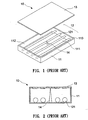
- a direct light back light module 10 comprises a rectangular frame 11 having a container 111. a light source module 12, a diffuser 13, and a supporting rod 14.
- the surface of the container 111 has a reflection layer 112 to reflect the light beam provided by the light source module 12 to the diffuser 13.
- the light source module 12 comprises a plurality of light tubes 121 side by side inside the container 111.
- the two ends of the diffuser 13 fix on a top surface 113 of the rectangular frame 11 and, then, the supporting rod 14 properly is placed on the bottom of the rectangular frame 11, which has one end holding the diffuser 13 to support the diffuser 13.
- the supporting rod 14 Due to the supporting rod 14 directly contacting the diffuser 13, the contact part hinders the light from passing.
- the supporting rod 14 generally uses a cone having a smaller cross-section on top point and, thus, the top of the supporting rod 14 directly contacts the diffuser 13 with a pointed tip.
- the deformation of the diffuser 13 is increasing and makes downward indentation.
- the pointed tip of the supporting rod 14 easily protrudes the diffuser 13 so the diffuser 13 forms a uneven surface or even causes the unequal interval between the diffuser 13 and the light source module 12 such that the diffuser 13 has uneven brightness.
- the LCD panel display images have light and shade phenomenon.
- the supporting rod 14 is placed inside the container 111.
- the light source providing light beams impinging onto the surface of the supporting rod 14
- the light beams can't effectively reflect or transmissive and, hence, can't project to the surface of the diffuser 13, which easily causes illumination light source loss.
- the back light assembly includes at least one or more diffusion plate supporting members disposed between a reflection sheet and a diffusion plate, and having a complex structure including an elastic material in contact with the diffusion plate.
- the diffusion plate supporting member has a double-structure including a support portion having sufficient rigidity to prevent the diffusion plate from dropping down, and a contact portion having elasticity for contacting the diffusion plate.
- the contact portion is preferably made of a soft material, to prevent scratches on a contact area of the diffusion plate due to external impact.
- the flat type fluorescence lamp includes first and second substrates, a light-emitting layer disposed between the first and second substrates, a plurality of supporters selectively arranged on the first substrates and a light-scattering layer placed above the plurality of supporters.
- the shape of the supporters maybe varied and the supporters could be formed of a transparent material or materials having characteristics of scattering light, so that light generated from the flat luminescent lamp passes through a portion adjoining lower surfaces of the supporters.
- a cap may be provided to prevent the supporters and the light-scattering means from being damaged from mechanical friction and pressure between the supporters and the light-scattering means above the supporters.
- the cap may be a soft material.
- the cap may cover the plurality of supporters, or be fixed to an upper portion of the supporters.
- An object of the present invention is to provide a back light apparatus.
- the diffuser has the supporting buffer to reduce the deformation of the diffuser.
- Another object of the present invention is to provide a back light apparatus.
- the diffuser can avoid damage to provide high brightness and even lightness light source.
- Still another object of the present invention is to provide a back light apparatus.
- the diffuser is supported by the elastic device to keep the same space for providing high brightness and even lightness.
- Another object of the present invention is to provide a back light apparatus to reduce the illumination loss by means of the reflection layer.
- the back light apparatus of the present invention comprises a frame having a container, a light source module, a diffuser, and at least one elastic device.
- the inner surface of the container has a reflection layer
- the light source module has a plurality of cold cathode fluorescent lamps side by side placed inside the container.
- the diffuser is placed upon the top of the frame.
- the elastic device has one end fixed on the bottom of the container and has the other end pressed to the diffuser in case of downward deformation of the diffuser.
- the top of the elastic device has a protrusion which could be transparent materials or high reflection materials to avoid the spots.
- the bottom of the container could have a fixing base or a cavity for containing the elastic device. Further, the fixing base could have a reflection layer to raise the reflection area of the light beam.
- a back light apparatus 20 of the present invention comprises a rectangular frame 21, a light source module 22, a diffuser 23, at least one elastic device 24, and a cover 25.
- the rectangular frame 21 has a container 211 and a top 212, a bottom surface 2111and an inner surface 2112 of the container 211 have a reflection layer to reflect light beams provided by the light source 22 onto the diffuser 23.
- the light source module 22 is placed inside the container 211, which comprises a plurality of cold cathode fluorescent lamp 221 (CCFL).
- the lamps 221 have properly interval and horizontally placed inside the container 211, which has two ends respectively extending to the inner surface 2112 of the frame 21 for fasten.
- the diffuser 23 is placed upon the top 212 of the rectangular frame 21.
- the surface of the diffuser 23 facing to the lamps 221 is as a diffuser layer so the light beams through the diffuser layer causes the diffusion that makes the light beams even.
- the diffuser 23 is made by plastic material.
- the elastic device 24 is erected and placed inside the container 211, which has one end fixed on the bottom 2111 of the container 211 and the other end forming a space D with the diffuser 23 (as shown in FIG. 5A ).
- the elastic device 24 can be a transparent or high reflection-material spring, elastic piece or plastic element to reduce the effect upon reflection light passing through the diffuser 23.
- the cover 25 is covered on the top 212 of the frame 21, which has a winder 251 smaller than the area of the diffuser 23. Side edges of the cover 25 have a plurality of fixing openings 252 for screwing devices 253 to the top 212 of the frame 21 that clips the two ends of the diffuser 23 for fixing.
- the back light apparatus of the present invention is placed behind the LCD panel (not shown in drawing). Part of the light beams provided by the lamps 221 directly project to the diffuser 23, and part of the light beams reflected by the reflection layer of the inner of the container 211 project to the diffuser 23. Then, the light beams pass through the diffuser 23 causes the diffusion to provide high and even brightness for LCD panel to display images.
- the diffuser 23 of the back light apparatus 20 of the present invention has a space D with the elastic device 24 that can avoid effecting the light beam passing through the diffuser 23 and forming dark points.
- the temperature raises so the plastic diffuser 23 is heated and caused downward deformation.
- the diffuser 23 is supported by the elastic device 24 to reduce the deformation of the diffuser 23 and keep the same space for providing high and even brightness.
- the elastic device 24 can compress the elastic device 24 for buffer.
- the elastic device 24 doesn't protrude the diffuser 23 to avoid damaging the diffuser 23 to form an uneven surface. Furthermore, the elastic device 24 gradually provides more support to further prevent the diffuser 23 increasing deformation so the diffuser 23 has a better flat providing high and even brightness for LCD panel.
- the size of the diffuser 23 is bigger.
- the plastic diffuser 23 only fixes upon around the rectangular frame 21, and the central part of the diffuser 23 is easier to form downward deformation.
- one end of the elastic device 24 of the present invention is fixed to the bottom 2111 of the container 211, and the other end directly holds the diffuser 23 to stably support the diffuser 23.
- the deformation of the diffuser 23 can be reduced so that the diffuser 23 has a better flat to provide high and even brightness for LCD panel.
- the same or similar devices of the present embodiment uses the same marks as the above-mentioned first embodiment.
- the difference between the present embodiment and the above-mentioned embodiment is that the elastic device 24 could use a spring of metal.
- the elastic device 24 can collocate a protrusion 241 upon the elastic device 24 to replace the transparent or high reflection optical material spring to lower the cost.
- the protrusion 241 can be transparent or high reflection material.
- the present embodiment uses the cone and transparent-material as the protrusion 241, so the contacting area between the protrusion 241 and the diffuser 23 is decreased not to hinder the light beams and to avoid the diffuser 23 forming dark points.
- the protrusion 241 could be elastic material to prevent directly protruding the diffuser 23 to damage the diffuser 23 forming an indent. Besides, because the protrusion 241 placed inside the container 211, for avoiding the illumination loss, the protrusion 241 could have reflection layer on the surface.
- the bottom 2111 of the container 211 has a cavity 213 for placing the elastic device 24.
- the protrusion 241 fixes upon the elastic device 24, which protrudes out of the top of the cavity 213 and keeps a space D1 with the diffuser 23 or presses to the diffuser 23.
- the spring 24A having bad reflection is hidden inside the cavity 213 to reduce hindering the light beams.
- the light beams provided by the lamps 221 can be reflected by the protrusion 241 and projected onto the diffuser 23 to reduce the illumination loss and shadow.
- the bottom 2111 of the container 211 has the cavity 213 to place the elastic device 24 inside the cavity 213.
- An opening 2131 of the cavity 213 is smaller than the than the diameter of the elastic device 24.
- the bottom of the protrusion 241 has a flange 2411.
- the flange 2411 is mounted in the cavity 213 to limit only the protrusion 241 out of the cavity 213.
- the protrusion 241 keeps a space D2 with the diffuser 23 or presses to the diffuser 23.
- the light beams provided by the lamps 221 could be reflected by the protrusion 241 to the diffuser 23 as being used.
- properly set original elasticity of the elastic device 24 so that could reduce the illumination loss and shadow caused by the deformation of the diffuser 23.
- a fixing base 214 is arranged on the bottom 2111 of the container 211.
- the fixing base 214 could contain the elastic device 24 so the volume of the back light apparatus 20 won't increase to shrink the product volume.
- the size of an opening 2141 of the fixing base 214 is smaller than the diameter of the elastic device 24 and the surface of the fixing base 214 has a reflection layer.
- the bottom of the protrusion 241 has a flange 2411.
- the flange 2411 is mounted in the fixing base 214 to limit only the protrusion 241 out of the fixing base 214.
- the protrusion 241 keeps a space D3 with the diffuser 23 or presses to the diffuser 23.
- the light beams provided by the lamps 221 could be reflected by the protrusion 241 and the reflection layer of the fixing base 214 to the diffuser 23 to reduce the illumination loss and shadow caused by the deformation of the elastic device 24.
Landscapes
- Physics & Mathematics (AREA)
- General Physics & Mathematics (AREA)
- Optics & Photonics (AREA)
- Liquid Crystal (AREA)
- Planar Illumination Modules (AREA)
Description
- The present invention relates to a liquid crystal display, and more particularly to a back light apparatus for use in a liquid crystal display.
- A back light module is the key component for liquid crystal display (LCD). By means of the brightness and uniform light source being provided by the backlight module, the LCD panel can display images.
- The backlight module can divide into a sidelight mode and a direct light mode according to the position of the light source. The sidelight mode places lamps of the light source on the side edge of a LCD panel and, then, uses a guiding-panel to control light path so that light beams project to a diffuser below the panel and provide uniform light beams. Because of the position of the light source, it suits being used in a light, thin, and power saving display equipment, e.g. a monitor of a notebook. But for big size display and brightness occasions, e.g. TV and desk PC. The sidelight mode can't provide enough brightness. Hence, it needs the direct light mode to directly place the light source below the display panel. The contain space for the light source is bigger, and has a capacity for over two lamps to increase the brightness of the light source and satisfy what's need.
- Referring to
FIG. 1 and FIG. 2 , a direct lightback light module 10 comprises arectangular frame 11 having acontainer 111. alight source module 12, adiffuser 13, and a supportingrod 14. The surface of thecontainer 111 has areflection layer 112 to reflect the light beam provided by thelight source module 12 to thediffuser 13. Thelight source module 12 comprises a plurality oflight tubes 121 side by side inside thecontainer 111. The two ends of thediffuser 13 fix on atop surface 113 of therectangular frame 11 and, then, the supportingrod 14 properly is placed on the bottom of therectangular frame 11, which has one end holding thediffuser 13 to support thediffuser 13. - Due to the supporting
rod 14 directly contacting thediffuser 13, the contact part hinders the light from passing. For avoiding thediffuser 13 forming bigger dark area, the supportingrod 14 generally uses a cone having a smaller cross-section on top point and, thus, the top of the supportingrod 14 directly contacts thediffuser 13 with a pointed tip. As the size of theback light module 10 increasing or the inside temperature of theframe 11 raising that causes by thelight source module 12, the deformation of thediffuser 13 is increasing and makes downward indentation. Meanwhile, the pointed tip of the supportingrod 14 easily protrudes thediffuser 13 so thediffuser 13 forms a uneven surface or even causes the unequal interval between thediffuser 13 and thelight source module 12 such that thediffuser 13 has uneven brightness. The LCD panel display images have light and shade phenomenon. In addition, the supportingrod 14 is placed inside thecontainer 111. As the light source providing light beams impinging onto the surface of the supportingrod 14, the light beams can't effectively reflect or transmissive and, hence, can't project to the surface of thediffuser 13, which easily causes illumination light source loss. -
US 2002/0044437 A1 describes a back light assembly for liquid crystal display device. Herein, the back light assembly includes at least one or more diffusion plate supporting members disposed between a reflection sheet and a diffusion plate, and having a complex structure including an elastic material in contact with the diffusion plate. The diffusion plate supporting member has a double-structure including a support portion having sufficient rigidity to prevent the diffusion plate from dropping down, and a contact portion having elasticity for contacting the diffusion plate. The contact portion is preferably made of a soft material, to prevent scratches on a contact area of the diffusion plate due to external impact. -
US 2002/0070660 A1 describes a flat type fluorescence lamp. Herein, the flat type fluorescence lamp includes first and second substrates, a light-emitting layer disposed between the first and second substrates, a plurality of supporters selectively arranged on the first substrates and a light-scattering layer placed above the plurality of supporters. The shape of the supporters maybe varied and the supporters could be formed of a transparent material or materials having characteristics of scattering light, so that light generated from the flat luminescent lamp passes through a portion adjoining lower surfaces of the supporters. Furthermore, a cap may be provided to prevent the supporters and the light-scattering means from being damaged from mechanical friction and pressure between the supporters and the light-scattering means above the supporters. The cap may be a soft material. In addition, the cap may cover the plurality of supporters, or be fixed to an upper portion of the supporters. - An object of the present invention is to provide a back light apparatus. By means of the elastic device, the diffuser has the supporting buffer to reduce the deformation of the diffuser.
- Another object of the present invention is to provide a back light apparatus. By means of the buffer provided by the elastic device, the diffuser can avoid damage to provide high brightness and even lightness light source.
- Still another object of the present invention is to provide a back light apparatus. The diffuser is supported by the elastic device to keep the same space for providing high brightness and even lightness.
- Further another object of the present invention is to provide a back light apparatus to reduce the illumination loss by means of the reflection layer.
- These objects are solved by the back light apparatus according to claim 1. Further advantages, refinements and embodiments of the invention are described in the respective sub-claims.
- In particular, the back light apparatus of the present invention comprises a frame having a container, a light source module, a diffuser, and at least one elastic device. The inner surface of the container has a reflection layer, and the light source module has a plurality of cold cathode fluorescent lamps side by side placed inside the container. The diffuser is placed upon the top of the frame. The elastic device has one end fixed on the bottom of the container and has the other end pressed to the diffuser in case of downward deformation of the diffuser. The top of the elastic device has a protrusion which could be transparent materials or high reflection materials to avoid the spots. In addition, the bottom of the container could have a fixing base or a cavity for containing the elastic device. Further, the fixing base could have a reflection layer to raise the reflection area of the light beam.
- The above and other objects, advantages, and features of the present invention will be understood from the following detailed description of the invention when considered in connection with the accompanying drawings below.
-
FIG. 1 is an explored view showing a back light apparatus of a direct light mode of the prior art. -
FIG. 2 is a sectional view showing a back light apparatus of a direct light mode of the prior art. -
FIG. 3 is an explored view showing the first embodiment of a back light apparatus of the present invention. -
FIG. 4 is a sectional view showing the first embodiment of a back light apparatus of the present invention. -
FIG. 5A, 5B and 5C are active schematic views showing the first embodiment of a back light apparatus of the present invention. -
FIG. 6 is a sectional view showing the elastic device for a back light apparatus of a first embodiment of the present invention. -
FIG. 7, FIG. 8 ,FIG. 9, and FIG. 10 are schematic views showing a back light apparatus having a cavity of the second embodiment of the present invention. - Referring to
FIG. 3 , aback light apparatus 20 of the present invention comprises arectangular frame 21, alight source module 22, adiffuser 23, at least oneelastic device 24, and acover 25. - The
rectangular frame 21 has acontainer 211 and a top 212, a bottom surface 2111and aninner surface 2112 of thecontainer 211 have a reflection layer to reflect light beams provided by thelight source 22 onto thediffuser 23. Thelight source module 22 is placed inside thecontainer 211, which comprises a plurality of cold cathode fluorescent lamp 221 (CCFL). Thelamps 221 have properly interval and horizontally placed inside thecontainer 211, which has two ends respectively extending to theinner surface 2112 of theframe 21 for fasten. Thediffuser 23 is placed upon the top 212 of therectangular frame 21. The surface of thediffuser 23 facing to thelamps 221 is as a diffuser layer so the light beams through the diffuser layer causes the diffusion that makes the light beams even. Thediffuser 23 is made by plastic material. Theelastic device 24 is erected and placed inside thecontainer 211, which has one end fixed on thebottom 2111 of thecontainer 211 and the other end forming a space D with the diffuser 23 (as shown inFIG. 5A ). Theelastic device 24 can be a transparent or high reflection-material spring, elastic piece or plastic element to reduce the effect upon reflection light passing through thediffuser 23. As shown inFIG. 4 , thecover 25 is covered on the top 212 of theframe 21, which has awinder 251 smaller than the area of thediffuser 23. Side edges of thecover 25 have a plurality of fixingopenings 252 for screwingdevices 253 to the top 212 of theframe 21 that clips the two ends of thediffuser 23 for fixing. - The back light apparatus of the present invention is placed behind the LCD panel (not shown in drawing). Part of the light beams provided by the
lamps 221 directly project to thediffuser 23, and part of the light beams reflected by the reflection layer of the inner of thecontainer 211 project to thediffuser 23. Then, the light beams pass through thediffuser 23 causes the diffusion to provide high and even brightness for LCD panel to display images. - As shown in
FIG. 5A , thediffuser 23 of the backlight apparatus 20 of the present invention has a space D with theelastic device 24 that can avoid effecting the light beam passing through thediffuser 23 and forming dark points. As thelight source module 22 using for a period, the temperature raises so theplastic diffuser 23 is heated and caused downward deformation. Referring toFIG. 5B , as contacting with theelastic device 24, thediffuser 23 is supported by theelastic device 24 to reduce the deformation of thediffuser 23 and keep the same space for providing high and even brightness. As the deformation of thediffuser 23 increasing to press theelastic device 24, referring toFIG. 5C , theelastic device 24 can compress theelastic device 24 for buffer. Hence, theelastic device 24 doesn't protrude thediffuser 23 to avoid damaging thediffuser 23 to form an uneven surface. Furthermore, theelastic device 24 gradually provides more support to further prevent thediffuser 23 increasing deformation so thediffuser 23 has a better flat providing high and even brightness for LCD panel. - Referring to
FIG. 6 , for the size of the monitor becomes bigger; the size of thediffuser 23 is bigger. Theplastic diffuser 23 only fixes upon around therectangular frame 21, and the central part of thediffuser 23 is easier to form downward deformation. Hence, one end of theelastic device 24 of the present invention is fixed to thebottom 2111 of thecontainer 211, and the other end directly holds thediffuser 23 to stably support thediffuser 23. Thus, the deformation of thediffuser 23 can be reduced so that thediffuser 23 has a better flat to provide high and even brightness for LCD panel. - Referring to
FIG. 7 , the same or similar devices of the present embodiment uses the same marks as the above-mentioned first embodiment. The difference between the present embodiment and the above-mentioned embodiment is that theelastic device 24 could use a spring of metal. Theelastic device 24 can collocate aprotrusion 241 upon theelastic device 24 to replace the transparent or high reflection optical material spring to lower the cost. Theprotrusion 241 can be transparent or high reflection material. The present embodiment uses the cone and transparent-material as theprotrusion 241, so the contacting area between theprotrusion 241 and thediffuser 23 is decreased not to hinder the light beams and to avoid thediffuser 23 forming dark points. In addition, theprotrusion 241 could be elastic material to prevent directly protruding thediffuser 23 to damage thediffuser 23 forming an indent. Besides, because theprotrusion 241 placed inside thecontainer 211, for avoiding the illumination loss, theprotrusion 241 could have reflection layer on the surface. - Referring to
FIG. 8 , thebottom 2111 of thecontainer 211 has acavity 213 for placing theelastic device 24. Theprotrusion 241 fixes upon theelastic device 24, which protrudes out of the top of thecavity 213 and keeps a space D1 with thediffuser 23 or presses to thediffuser 23. The spring 24A having bad reflection is hidden inside thecavity 213 to reduce hindering the light beams. Hence, the light beams provided by thelamps 221 can be reflected by theprotrusion 241 and projected onto thediffuser 23 to reduce the illumination loss and shadow. - In addition, referring to
FIG. 9 , thebottom 2111 of thecontainer 211 has thecavity 213 to place theelastic device 24 inside thecavity 213. Anopening 2131 of thecavity 213 is smaller than the than the diameter of theelastic device 24. The bottom of theprotrusion 241 has aflange 2411. Theflange 2411 is mounted in thecavity 213 to limit only theprotrusion 241 out of thecavity 213. Theprotrusion 241 keeps a space D2 with thediffuser 23 or presses to thediffuser 23. The light beams provided by thelamps 221 could be reflected by theprotrusion 241 to thediffuser 23 as being used. In addition, according the size of thediffuser 23, properly set original elasticity of theelastic device 24 so that could reduce the illumination loss and shadow caused by the deformation of thediffuser 23. - Referring to
FIG. 10 , a fixingbase 214 is arranged on thebottom 2111 of thecontainer 211. The fixingbase 214 could contain theelastic device 24 so the volume of the backlight apparatus 20 won't increase to shrink the product volume. The size of anopening 2141 of the fixingbase 214 is smaller than the diameter of theelastic device 24 and the surface of the fixingbase 214 has a reflection layer. The bottom of theprotrusion 241 has aflange 2411. Theflange 2411 is mounted in the fixingbase 214 to limit only theprotrusion 241 out of the fixingbase 214. Theprotrusion 241 keeps a space D3 with thediffuser 23 or presses to thediffuser 23. The light beams provided by thelamps 221 could be reflected by theprotrusion 241 and the reflection layer of the fixingbase 214 to thediffuser 23 to reduce the illumination loss and shadow caused by the deformation of theelastic device 24.
Claims (9)
- A back light apparatus (20), comprising:- a frame (21), which has a container (211) with a reflection layer in an inner surface (2112);- a light source module (22), which is placed inside said container (211);- a diffuser (23), which is placed upon said light source module (22); and- at least one elastic device (24) placed inside said container (211), which has one end fixed on a bottom (2111) of said container (211) and another end for supporting said diffuser (23), characterized in that there is a space (D1,D2,D3) between a top of said elastic device (24) and said diffuser (23) when said diffuser (24) is not deformed and supports said diffuser (23) in case of downward deformation of the diffuser (23), to reduce the deformation of said diffuser (23).
- The back light apparatus (20) according to claim 1, wherein said elastic device (24) is a transparent material or reflection material.
- The back light apparatus according to claim 1, wherein said elastic device (24) is a spring, an elastic piece or a plastic device.
- The back light apparatus (20) according to claim 1, wherein said elastic device (24) has a protrusion (241) on the top.
- The back light apparatus (20) according to claim 4, wherein said protrusion (241) is a high reflection material or a transparent material.
- The back light apparatus (20) according to claim 4, wherein said protrusion (241) is an elastic material.
- The back light apparatus (20) according to claim 4, wherein said protrusion (241) is a cone.
- The back light apparatus (20) according to claim 1, wherein said container (211) has a fixing base (214) on the bottom (2111), said elastic device (24) placed inside said fixing base (214) whose surface has a reflection layer and wherein said fixing base (214) has an opening (2141) whose size is smaller than the diameter of said elastic device (24), said elastic device having a protrusion (241) on the top.
the bottom of said protrusion having a flange (2411) mounted inside said fixing base (214). - The back light apparatus (20) according to claim 1, wherein said container (211) further comprises a cavity (213) on the bottom (2111), said elastic device (24) being placed inside said cavity (213) and wherein said cavity (213) has an opening (2131) whose size is smaller than the diameter of said elastic device (24), said elastic device (24) having a protrusion (241) on the top, the bottom of said protrusion (241) having a flange (2411) mounted inside said cavity (213).
Applications Claiming Priority (2)
| Application Number | Priority Date | Filing Date | Title |
|---|---|---|---|
| CN03101428 | 2003-01-06 | ||
| CN 03101428 CN1276299C (en) | 2003-01-06 | 2003-01-06 | Backlight plate device |
Publications (2)
| Publication Number | Publication Date |
|---|---|
| EP1435532A1 EP1435532A1 (en) | 2004-07-07 |
| EP1435532B1 true EP1435532B1 (en) | 2012-08-29 |
Family
ID=32477229
Family Applications (1)
| Application Number | Title | Priority Date | Filing Date |
|---|---|---|---|
| EP03028965A Expired - Lifetime EP1435532B1 (en) | 2003-01-06 | 2003-12-17 | Back light apparatus |
Country Status (2)
| Country | Link |
|---|---|
| EP (1) | EP1435532B1 (en) |
| CN (1) | CN1276299C (en) |
Families Citing this family (7)
| Publication number | Priority date | Publication date | Assignee | Title |
|---|---|---|---|---|
| CN100543630C (en) * | 2004-09-13 | 2009-09-23 | 新巨企业股份有限公司 | Control device for inhibiting temperature of display screen |
| CN100368889C (en) * | 2005-01-19 | 2008-02-13 | 财团法人工业技术研究院 | Backlight module with heat radiation structure |
| KR20060116549A (en) * | 2005-05-10 | 2006-11-15 | 삼성전자주식회사 | Backlight unit and LCD using the same |
| CN100359383C (en) * | 2005-06-21 | 2008-01-02 | 友达光电股份有限公司 | Backlight module of liquid crystal display and supporting structure thereof |
| EP2416057A4 (en) * | 2009-05-15 | 2012-12-26 | Sharp Kk | Illuminating device, display device, and television receiver |
| CN102748666B (en) * | 2012-06-19 | 2014-08-27 | 深圳市华星光电技术有限公司 | Direct type backlight module and liquid crystal displayer |
| CN103216791A (en) * | 2013-04-19 | 2013-07-24 | 深圳市华星光电技术有限公司 | Fixing structure of light guide plate and backlight module using same |
Citations (2)
| Publication number | Priority date | Publication date | Assignee | Title |
|---|---|---|---|---|
| US20020044437A1 (en) * | 2000-10-14 | 2002-04-18 | Lee Joung Jae | Back light assembly for liquid crystal display device |
| US20020070660A1 (en) * | 2000-12-07 | 2002-06-13 | Lg. Philips Lcd Co., Ltd. | Flat type fluorescent lamp |
Family Cites Families (2)
| Publication number | Priority date | Publication date | Assignee | Title |
|---|---|---|---|---|
| EP1070913B1 (en) * | 1999-07-23 | 2007-06-27 | Siteco Beleuchtungstechnik GmbH | Compact luminaire having a hollow light conductor |
| JP3719927B2 (en) * | 1999-12-27 | 2005-11-24 | シャープ株式会社 | Illumination device and liquid crystal display |
-
2003
- 2003-01-06 CN CN 03101428 patent/CN1276299C/en not_active Expired - Fee Related
- 2003-12-17 EP EP03028965A patent/EP1435532B1/en not_active Expired - Lifetime
Patent Citations (2)
| Publication number | Priority date | Publication date | Assignee | Title |
|---|---|---|---|---|
| US20020044437A1 (en) * | 2000-10-14 | 2002-04-18 | Lee Joung Jae | Back light assembly for liquid crystal display device |
| US20020070660A1 (en) * | 2000-12-07 | 2002-06-13 | Lg. Philips Lcd Co., Ltd. | Flat type fluorescent lamp |
Also Published As
| Publication number | Publication date |
|---|---|
| EP1435532A1 (en) | 2004-07-07 |
| CN1515935A (en) | 2004-07-28 |
| CN1276299C (en) | 2006-09-20 |
Similar Documents
| Publication | Publication Date | Title |
|---|---|---|
| US7128461B2 (en) | Back light apparatus | |
| US6974221B2 (en) | Support for backlight module | |
| KR100959685B1 (en) | Backlight retention assembly | |
| US7510317B2 (en) | Illuminating device for display device | |
| US7481569B2 (en) | Direct type backlight module | |
| US7929073B2 (en) | Liquid crystal display module and method for assembling the same | |
| US20050206805A1 (en) | Back light assembly and liquid crystal display device having the same | |
| KR20100033196A (en) | Supporting member for supporting optical member and display apparatus having the same | |
| KR101312684B1 (en) | Lamp Guide and the Liquid Crystal Display Device | |
| CN101510026B (en) | Liquid crystal display device | |
| JP4872696B2 (en) | Curved surface light source device and method for manufacturing curved liquid crystal display device | |
| JP2002090736A (en) | Backlight for flat panel display | |
| US8057058B2 (en) | Lighting device for display device, display device and television receiver | |
| EP1435532A1 (en) | Back light apparatus | |
| KR100589780B1 (en) | Support for LCD Panel | |
| US7443462B2 (en) | Light guide plate structure with inlaid block-shaped light scattering elements protruding out bottom and back light module | |
| KR20050116642A (en) | Supporter for lcd panel | |
| JP5088713B2 (en) | Liquid crystal display | |
| JP4924349B2 (en) | Liquid crystal display | |
| KR100949486B1 (en) | LCD Display | |
| KR101651676B1 (en) | Liquid crystal display device | |
| KR20090093179A (en) | Liquid crystal display device | |
| KR20080061818A (en) | Backlight Assembly of Liquid Crystal Display | |
| KR20040007772A (en) | Direct light type backlight assembly of liquid crystal display | |
| KR20060044015A (en) | Back light assembly and liquid crystal display device having same |
Legal Events
| Date | Code | Title | Description |
|---|---|---|---|
| PUAI | Public reference made under article 153(3) epc to a published international application that has entered the european phase |
Free format text: ORIGINAL CODE: 0009012 |
|
| 17P | Request for examination filed |
Effective date: 20040512 |
|
| AK | Designated contracting states |
Kind code of ref document: A1 Designated state(s): AT BE BG CH CY CZ DE DK EE ES FI FR GB GR HU IE IT LI LU MC NL PT RO SE SI SK TR |
|
| AX | Request for extension of the european patent |
Extension state: AL LT LV MK |
|
| AKX | Designation fees paid |
Designated state(s): DE FR |
|
| 17Q | First examination report despatched |
Effective date: 20061120 |
|
| GRAJ | Information related to disapproval of communication of intention to grant by the applicant or resumption of examination proceedings by the epo deleted |
Free format text: ORIGINAL CODE: EPIDOSDIGR1 |
|
| GRAP | Despatch of communication of intention to grant a patent |
Free format text: ORIGINAL CODE: EPIDOSNIGR1 |
|
| GRAP | Despatch of communication of intention to grant a patent |
Free format text: ORIGINAL CODE: EPIDOSNIGR1 |
|
| GRAS | Grant fee paid |
Free format text: ORIGINAL CODE: EPIDOSNIGR3 |
|
| GRAA | (expected) grant |
Free format text: ORIGINAL CODE: 0009210 |
|
| AK | Designated contracting states |
Kind code of ref document: B1 Designated state(s): DE FR |
|
| REG | Reference to a national code |
Ref country code: DE Ref legal event code: R096 Ref document number: 60341936 Country of ref document: DE Effective date: 20121025 |
|
| PG25 | Lapsed in a contracting state [announced via postgrant information from national office to epo] |
Ref country code: FR Free format text: LAPSE BECAUSE OF NON-PAYMENT OF DUE FEES Effective date: 20121231 |
|
| PLBE | No opposition filed within time limit |
Free format text: ORIGINAL CODE: 0009261 |
|
| STAA | Information on the status of an ep patent application or granted ep patent |
Free format text: STATUS: NO OPPOSITION FILED WITHIN TIME LIMIT |
|
| 26N | No opposition filed |
Effective date: 20130530 |
|
| REG | Reference to a national code |
Ref country code: DE Ref legal event code: R097 Ref document number: 60341936 Country of ref document: DE Effective date: 20130530 |
|
| PGFP | Annual fee paid to national office [announced via postgrant information from national office to epo] |
Ref country code: DE Payment date: 20141208 Year of fee payment: 12 |
|
| PGFP | Annual fee paid to national office [announced via postgrant information from national office to epo] |
Ref country code: FR Payment date: 20141212 Year of fee payment: 12 |
|
| REG | Reference to a national code |
Ref country code: DE Ref legal event code: R119 Ref document number: 60341936 Country of ref document: DE |
|
| REG | Reference to a national code |
Ref country code: FR Ref legal event code: ST Effective date: 20160831 |
|
| PG25 | Lapsed in a contracting state [announced via postgrant information from national office to epo] |
Ref country code: DE Free format text: LAPSE BECAUSE OF NON-PAYMENT OF DUE FEES Effective date: 20160701 |
|
| PG25 | Lapsed in a contracting state [announced via postgrant information from national office to epo] |
Ref country code: FR Free format text: LAPSE BECAUSE OF NON-PAYMENT OF DUE FEES Effective date: 20151231 |