EP1435526A1 - Radiowave location detector for bearing and position determination - Google Patents
Radiowave location detector for bearing and position determination Download PDFInfo
- Publication number
- EP1435526A1 EP1435526A1 EP02800221A EP02800221A EP1435526A1 EP 1435526 A1 EP1435526 A1 EP 1435526A1 EP 02800221 A EP02800221 A EP 02800221A EP 02800221 A EP02800221 A EP 02800221A EP 1435526 A1 EP1435526 A1 EP 1435526A1
- Authority
- EP
- European Patent Office
- Prior art keywords
- output
- directional antenna
- receiving
- differential
- detection signal
- Prior art date
- Legal status (The legal status is an assumption and is not a legal conclusion. Google has not performed a legal analysis and makes no representation as to the accuracy of the status listed.)
- Withdrawn
Links
Images




Classifications
-
- H—ELECTRICITY
- H01—ELECTRIC ELEMENTS
- H01Q—ANTENNAS, i.e. RADIO AERIALS
- H01Q25/00—Antennas or antenna systems providing at least two radiating patterns
- H01Q25/02—Antennas or antenna systems providing at least two radiating patterns providing sum and difference patterns
-
- G—PHYSICS
- G01—MEASURING; TESTING
- G01S—RADIO DIRECTION-FINDING; RADIO NAVIGATION; DETERMINING DISTANCE OR VELOCITY BY USE OF RADIO WAVES; LOCATING OR PRESENCE-DETECTING BY USE OF THE REFLECTION OR RERADIATION OF RADIO WAVES; ANALOGOUS ARRANGEMENTS USING OTHER WAVES
- G01S3/00—Direction-finders for determining the direction from which infrasonic, sonic, ultrasonic or electromagnetic waves, or particle emission, not having a directional significance, are being received
- G01S3/02—Direction-finders for determining the direction from which infrasonic, sonic, ultrasonic or electromagnetic waves, or particle emission, not having a directional significance, are being received using radio waves
- G01S3/14—Systems for determining direction or deviation from predetermined direction
- G01S3/28—Systems for determining direction or deviation from predetermined direction using amplitude comparison of signals derived simultaneously from receiving antennas or antenna systems having differently-oriented directivity characteristics
- G01S3/32—Systems for determining direction or deviation from predetermined direction using amplitude comparison of signals derived simultaneously from receiving antennas or antenna systems having differently-oriented directivity characteristics derived from different combinations of signals from separate antennas, e.g. comparing sum with difference
- G01S3/36—Systems for determining direction or deviation from predetermined direction using amplitude comparison of signals derived simultaneously from receiving antennas or antenna systems having differently-oriented directivity characteristics derived from different combinations of signals from separate antennas, e.g. comparing sum with difference the separate antennas having differently-oriented directivity characteristics
-
- G—PHYSICS
- G01—MEASURING; TESTING
- G01S—RADIO DIRECTION-FINDING; RADIO NAVIGATION; DETERMINING DISTANCE OR VELOCITY BY USE OF RADIO WAVES; LOCATING OR PRESENCE-DETECTING BY USE OF THE REFLECTION OR RERADIATION OF RADIO WAVES; ANALOGOUS ARRANGEMENTS USING OTHER WAVES
- G01S5/00—Position-fixing by co-ordinating two or more direction or position line determinations; Position-fixing by co-ordinating two or more distance determinations
- G01S5/02—Position-fixing by co-ordinating two or more direction or position line determinations; Position-fixing by co-ordinating two or more distance determinations using radio waves
- G01S5/04—Position of source determined by a plurality of spaced direction-finders
Definitions
- the present invention relates to a direction and position finding apparatus which receives radio wave and determines the direction of arrival and the position of the emission source thereof with high accuracy.
- One of the well-known prior basic direction finding apparatuses to detect the direction of arrival of radio wave is, for example, Yagi antenna which detects the direction of arrival of the radio wave using a directional antenna.
- Another direction finding apparatus is disclosed in the Japanese Patent Application No. H3-67789, which uses a non-directional antenna and a directional antenna to determine the direction.
- These conventional types of detection apparatuses provide a system to assume an azimuth angle using the directional characteristic of the antenna.
- the present invention is made to solve the problems described above, and an object thereof is to provide a direction and position finding apparatus capable of not only detecting the direction of arrival of radio wave with high accuracy, but also performing a highly accurate position finding of the emission source thereof, in other words, to provide a direction and position finding apparatus capable of performing detection of both the direction of arrival and the emission source of radio wave with a higher accuracy thah used to be.
- the radio direction and position finding apparatus in accordance with the present invention comprises; a first directional antenna which rotates with a desired angle of elevation; a first phase integral means for producing an output through an integration of output from the first directional antenna; a first phase difference means for producing an output as a difference of the outputs from the first directional antenna; a first frequency dividing means for dividing frequency of integral component of the output from the first directional antenna; a first differential gain control means for controlling gain of differential component of the output from the first directional antenna; a first receiving means for receiving output from the first frequency dividing means and producing a detection signal output; a second receiving means for receiving output from the first differential gain control means and producing a detection signal output; a first subtraction means for subtracting one detection signal output from the other detection signal output of the first and the second receiving means; a first calculation means for determining a direction of arrival of radio wave based on output from the first subtraction means; a second directional antenna which rotates with a desired angle of elevation; a second
- each of the first and the second directional antennas may use at least two vertical polarized waves.
- antenna pattern means received signals corresponding respectively to the horizontal plane and the vertical plane of each of the directional antennas.
- one of the first and the second directional antennas may use a vertical polarized radio wave with acute horizontal directivity, and the other of the first and the second directional antennas may use a vertical polarized radio wave with acute vertical directivity.
- the phase integral means may be constructed to integrate the strength of electrical field component received at the first and the second directional antennas.
- signals of the same frequency are integrated so that it is possible to intensify the same phase components and detect more accurately the direction of the emission source of the radio wave.
- the phase difference means may be constructed to be capable of setting the phase difference based on outputs from the first and the second directional antennas in providing the difference.
- the radio direction and position finding apparatus may be provided with means for controlling the gain of the differential component of the output from each of the first and the second directional antennas to thereby determine the position of the emission source of the radio wave.
- the apparatus constructed as described above can determine the direction of arrival of the radio wave by interlockingly rotating the two directional antennas to maximize the integral output and also determine the position of the emission source of the radio wave by controlling the angle of elevation while controlling the gain of the differential output.
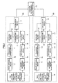
- FIG.1 A block diagram of a radio direction and position finding apparatus according to the present invention is shown in FIG.1.
- the radio direction and position finding apparatus according to the present invention comprises a directional antenna 1 having a one-column two-row vertical polarized wave directivity and a directional antenna 10 having a two-column one-row vertical polarized wave directivity.
- the directional antennas 1 and 10 can interlockingly rotate respectively with predetermined angles of elevation.
- Phase integral means 2 and 11 receive signals received by the directional antennas 1 and 10, respectively, and each of the means 2 and 11 multiplies the signals received by each of the antennas to generate (calculate) an integral signal based on corresponding one of these two received signals to provide an output.
- a conventional antenna such as an antenna for TV having a plurality of elements combined together
- FIG.8(a) shows an antenna output A
- FIG.8(b) shows an antenna output B
- Sum of antenna output A with antenna output B (A+B), and their multiplication (A ⁇ B) are as shown in FIGs.8(c) and (d) respectively.
- the width of the angle W 0 remains the same both in the summing and the multiplication, however, it will be noted that the width of the angle W 2 made by the multiplication becomes far narrower than that of the angle W, made by summing and the height H 2 made by the multiplication becomes far larger than that of a height H, under the summing.
- each of the phase difference means 3 and 12 can respectively set the phase difference of each of these two directional antennas 1 and 10 to a desired value.
- Frequency dividing means 4 and 13 function to divide the frequencies of integral signals outputted from the respective ones of the phase integral means 2 and 9.
- the frequency of integral signal is divided into a half, but on the contrary, the frequency of differential signal may be doubled.
- Gain control means 5 and 14 function to control the gain of the differential signals outputted from corresponding ones of the phase difference means 3 and 12. The gain of the differential signal will be set at a desired value.
- Receiving means 6 and 15 function to detect the integral signals outputted from the frequency dividing means 4 and 13, and receiving means 8 and 17 function to detect the differential signals outputted after the gain control from the gain control means 5 and 14.
- Each of the subtraction means 7 and 16 calculates a difference between the detected output from the corresponding one of the receiving means 6 and 15 and that from the corresponding one of the receiving means 8 and 17.
- Each of the calculation means 9 and 18 determines the direction of arrival of the radio wave received by the corresponding one of the directional antennas 1 and 10 by determining the maximum value based on the output from the corresponding one of the subtraction means 7 and 16. The results are applied to the position determining calculation means 19 to determine the position of the emission source of the radios wave from the relationship between the maximum value and the angle from the central axis of each of directional antennas 1 and 10.
- the one-column two-row vertical polarized wave directional antenna 1 and the two-column one-row vertical polarized wave directional antenna 10 are oriented toward the same direction and have predetermined directivities, respectively.
- the antennas 1 and 10 are adjustable in angle of elevation and function to output received signals, respectively corresponding to horizontal and vertical planes (hereafter each being referred as an antenna pattern.)
- each of the directional antennas 1 and 10 is inputted to the corresponding one of the phase integral means 2 and 11, to have the multiplication to be carried out.
- the in-phase components are subjected to square calculation so that the output will be greater than that obtained by summing.
- the half value angle of antenna directivity (3dB band width) has a value narrower and sharper than that of summing calculation.
- the integral patterns outputted from the phase integral means 2 and 11 have double value of frequency as the result of multiplication, so that it is inputted to the frequency dividing means 4 and 13 to return the double value of frequency to the original one before it is inputted to the receiving means 6 and 15.
- the antenna pattern of each of the directional antennas 1 and 10 is also inputted to each of phase difference means 3 and 12, so that the difference calculation is done accordingly.
- the differential pattern outputted from each of phase difference means 3 and 12 is inputted, to each of the gain control means 5 and 14 to have the gain controlled accordingly before it is inputted to each of receiving means 8 and 17.
- the receiving means 6 and 8 and the receiving means 15 and 17 provide respectively the detection signals from the integration signal outputs and the differential outputs and supply these signals to the subtraction means 7 and 16.
- the subtraction means 7 and 16 respectively function to subtract the output values of the detection signals of the differential outputs from the output values of the detection signals of the integral signal outputs to calculate angular properties of these differences (hereafter referred as an integration-differential pattern), and respectively output the angular properties to the calculation means 9 and 18.
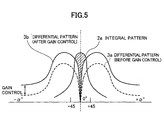
- FIGs.4 and 5 show the integration pattern and the differential pattern.
- the reference character a designates an azimuth angle.
- FIGs.4 and 5 show the case wherein the received signals of the directional antennas 1 and 10 are calculated in the integral means 2 and 11 and the difference means 3 and 12 in FIG.1, the axis of abscissas being the angle (the azimuth angle) from the central axis of each of the directional antennas 1 and 10 whereas the vertical axis being the received signal outputs of each of the directional antennas 1 and 10.
- the integration-differential pattern or the angular property shows a steep level change in the vicinity of the front side of the antenna. This indicates that the beam width (a half value angle) of the antenna is equivalently narrower in the integration-differential pattern than in the integration pattern. Further, the integration pattern outputs have steeper characteristics than the summing pattern outputs do. Accordingly, a highly accurate direction finding can be achieved.
- the differential pattern in the integration-differential pattern can be shifted by controlling the gain 'of the differential pattern in the gain control means. The example is shown in FIG.5. This gain control makes it possible with high accuracy to detect the maximum point with respect to the arrival position of the radio wave.
- the integration pattern in FIG.5 (hatched portion) constrained to a narrow range by the gain control of the differential pattern and also to detect with high accuracy the maximum value of the length of the hatched portion parallel with the vertical axis (the length along the vertical axis of a portion of the integration pattern, the portion being obtained by deleting from the overall configuration of the integration pattern such portion that overlaps with the configuration of the differential pattern), the length showing the received level(strength).
- FIG.6 shows the directivity of the one-column two-row vertical polarized wave directional antenna 1 and the directivity of the two-column one-row vertical polarized wave directional antenna 10.
- the directivities can be designated by the patterns in planes directed in up and down (vertical) direction and left and right (horizontal) direction. Because of the combination of the directivities, the one-column two-row vertical polarized wave directional antenna 1 shows an output having a directivity with the integration-differential pattern which is steep shaped along the up and down (vertical) direction.
- the two-column one-row vertical polarized wave directional antenna 10 shows an output having a directivity with integration-differential pattern which is steep shaped along the left and right (horizontal) direction.
- the calculation means 9 and 18 function to detect the direction of arrival of the radio wave by calculating the levels bf the integration patterns while the directional antennas 1 and 10 are rotated about the vertical axis of a supporting structure for supporting the directional antennas 1 and 10 to detect and determine the directions wherein the levels show the maximum values.
- the directions of the maximum values thus indicate the directions of arrival of the radio wave.
- the position can be determined.
- FIG.7 shows an embodiment for measuring the direction of arrival and the position of the emission source of a radio wave along an extension of a road by the direction and position finding apparatus in accordance with the present invention.
- (a) is a side elevational view
- (b) is a plan view.
- the directional antenna is set to have a angle of elevation to determine a measuring range on the road surface.
- the azimuth angle (direction) is then adjusted so that a maximum value of the integration pattern is obtained and the gain of the differential pattern is adjusted so as to make it possible to measure with high accuracy the position of the emission source of the radio wave.
- the position of the emission source of the radio wave can be measured by rotating the antenna within a horizontal plane.
- the direction and position finding apparatus for radio wave comprises: a first directional antenna which rotates with a desired angle of elevation; a first phase integral means for producing an output through an integration of output from the first directional antenna; a first phase difference means for producing an output as a difference of the outputs from the first directional antenna; a first frequency dividing means for dividing frequency of the integral component of the output from the first directional antenna; a first differential gain control means for controlling gain of differential component of the output from the first directional antenna; a first receiving means for receiving output from the first frequency dividing means and producing a detection signal output; a second receiving means for receiving output from the first differential gain control means and producing a detection signal output; a first subtraction means for subtracting one detection signal output from the other detection signal output of the first and the second receiving means; a first calculation means for specifying a direction of arrival of radio wave based on output from the first subtraction means; a second directional antenna which rotates with a desired angle of elevation; a second phase integral
Landscapes
- Physics & Mathematics (AREA)
- Engineering & Computer Science (AREA)
- General Physics & Mathematics (AREA)
- Radar, Positioning & Navigation (AREA)
- Remote Sensing (AREA)
- Variable-Direction Aerials And Aerial Arrays (AREA)
- Position Fixing By Use Of Radio Waves (AREA)
- Radar Systems Or Details Thereof (AREA)
Abstract
Description
Claims (6)
- A radio direction and position finding apparatus comprising;wherein said directional antenna and said second directional antenna rotate interlockingly.a first directional antenna which rotates with a desired angle elevation;a first phase integral means for producing an output through an integration of output from said directional antenna;a first phase difference means for producing an output as a difference of the outputs from said first directional antenna;a first frequency dividing means for dividing frequency of integral component of the output from said directional antenna;a first differential gain control means for controlling gain of differential component of the output from said directional antenna;a first receiving means for receiving output from said first frequency dividing means and producing a detection signal output;a second receiving means for receiving output from said first differential gain control means and producing a detection signal output;a first subtraction means for subtracting one detection signal output from the other detection signal output of said first and second receiving means;a first calculation means for determining a direction of arrival of radio wave based on output from said first subtraction means;a second directional antenna which rotates with a desired angle of elevation;a second phase integral means for producing an output through an integration of output from said second directional antenna;a second phase difference means for producing an output as a difference of the outputs from said second directional antenna;a second frequency dividing means for dividing frequency of integral component of the output from said second directional antenna;a second differential gain control means for controlling gain of differential component of the output from said second directional antenna;a third receiving means for receiving output from said second frequency dividing means and producing a detection signal output;a fourth receiving means for receiving output from said second differential gain control means and producing a detection signal output;a second subtraction means for subtracting one detection signal output from the other detection signal output of said third and fourth receiving means;a second calculation means for determining a direction of arrival of radio wave based on output from said second subtraction means; anda position determining calculation means for determining the position of the emission source of the radio wave based on outputs from said first and second calculation means;
- A radio direction and position finding apparatus in accordance with claim 1, in which each of said first and second directional antennas uses at least two vertical polarized waves.
- A radio direction and position finding apparatus in accordance with claim 1 or 2, in which one of said first and second directional antennas is adapted to use a vertical polarized wave with an acute horizontal directivity, and the other of said first and second directional antennas is adapted to use a vertical polarized wave with an acute vertical directivity.
- A radio direction and position finding apparatus in accordance with anyone of claims 1 to 3 in which said phase integral means is adapted to integrate strength of electrical field component of said first and second directional antennas.
- A radio direction and position finding apparatus in accordance with anyone of claims 1 to 4 in which said phase difference means is capable of setting a phase difference based on outputs from said first and the second directional antennas in providing the differences.
- A radio direction and position finding apparatus in accordance with anyone of claims 1 to 5 in which the position of the emission source of the radio wave can be specified by adjusting gain of the differential component of the output from said first and second directional antennas.
Applications Claiming Priority (3)
| Application Number | Priority Date | Filing Date | Title |
|---|---|---|---|
| JP2001299220 | 2001-09-28 | ||
| JP2001299220A JP2003107144A (en) | 2001-09-28 | 2001-09-28 | Radio azimuth position detection device |
| PCT/JP2002/008993 WO2003029838A1 (en) | 2001-09-28 | 2002-09-04 | Radio wave bearing/location finder |
Publications (2)
| Publication Number | Publication Date |
|---|---|
| EP1435526A1 true EP1435526A1 (en) | 2004-07-07 |
| EP1435526A4 EP1435526A4 (en) | 2005-08-03 |
Family
ID=19120007
Family Applications (1)
| Application Number | Title | Priority Date | Filing Date |
|---|---|---|---|
| EP02800221A Withdrawn EP1435526A4 (en) | 2001-09-28 | 2002-09-04 | LOCATION LOCATOR / RADIO WAVE RECOVERY |
Country Status (5)
| Country | Link |
|---|---|
| US (1) | US6759982B2 (en) |
| EP (1) | EP1435526A4 (en) |
| JP (1) | JP2003107144A (en) |
| CA (1) | CA2445214A1 (en) |
| WO (1) | WO2003029838A1 (en) |
Cited By (2)
| Publication number | Priority date | Publication date | Assignee | Title |
|---|---|---|---|---|
| CN102102470A (en) * | 2009-12-18 | 2011-06-22 | 株式会社东海理化电机制作所 | Communication terminal position determination device |
| US8849229B2 (en) | 2012-06-01 | 2014-09-30 | Wisconsin Alumni Research Foundation | Electrically small, super directive antennas |
Families Citing this family (10)
| Publication number | Priority date | Publication date | Assignee | Title |
|---|---|---|---|---|
| KR100882351B1 (en) * | 2007-03-14 | 2009-02-12 | 한국전자통신연구원 | Position and direction tracking device and method using the RF signal |
| JP5006097B2 (en) * | 2007-04-24 | 2012-08-22 | 京セラ株式会社 | Reception control method and wireless communication apparatus |
| US8306473B2 (en) * | 2008-02-15 | 2012-11-06 | Qualcomm Incorporated | Methods and apparatus for using multiple antennas having different polarization |
| KR101062884B1 (en) * | 2009-10-09 | 2011-09-07 | 국방과학연구소 | 3D multibaseline bearing estimation method and device |
| RU2476900C1 (en) * | 2011-10-27 | 2013-02-27 | Научно-Исследовательский Испытательный Центр Систем Связи Федерального Государственного Учреждения "27 Центральный Научно-Исследовательский Институт Минобороны России" | Method of determining coordinates of radio-frequency sources |
| RU2560098C1 (en) * | 2014-04-22 | 2015-08-20 | Российская Федерация, от имени которой выступает Министерство обороны Российской Федерации | Radio monitoring method |
| CN105467380A (en) * | 2015-12-23 | 2016-04-06 | 常州安塔歌电子科技有限公司 | Method for measuring azimuth angle with application of sum and difference beam antennas and artificial satellite signals |
| KR101747789B1 (en) * | 2016-04-14 | 2017-06-15 | 국방과학연구소 | Polarization tracking system using dual polarization antenna with variable gain attenuator and the control method of the same |
| RU2692467C2 (en) * | 2016-08-29 | 2019-06-25 | Федеральное государственное казенное военное образовательное учреждение высшего образования "Военный учебно-научный центр Военно-воздушных сил "Военно-воздушная академия имени профессора Н.Е. Жуковского и Ю.А. Гагарина" (г. Воронеж) Министерства обороны Российской Федерации | Radar method |
| CN110082711B (en) * | 2019-02-27 | 2023-06-02 | 中国电子科技集团公司第三十六研究所 | Method and device for comparing and direction-finding |
Family Cites Families (15)
| Publication number | Priority date | Publication date | Assignee | Title |
|---|---|---|---|---|
| JPS5721671B2 (en) * | 1973-07-04 | 1982-05-08 | ||
| US4387373A (en) * | 1977-04-21 | 1983-06-07 | Westinghouse Electric Corp. | Synthetic monopulse radar |
| GB2253107B (en) * | 1982-03-05 | 1993-01-13 | Philips Electronic Associated | Locating moving radio sources |
| US4845502A (en) * | 1988-04-07 | 1989-07-04 | Carr James L | Direction finding method and apparatus |
| JPH0238886A (en) * | 1988-07-28 | 1990-02-08 | Mitsubishi Electric Corp | Radar |
| JP2676936B2 (en) | 1989-08-23 | 1997-11-17 | 三菱電機株式会社 | Orientation detection device |
| JP2619144B2 (en) | 1991-03-08 | 1997-06-11 | 三菱電機株式会社 | Direction finder |
| JP2964752B2 (en) | 1991-11-30 | 1999-10-18 | 日本電気株式会社 | Radio wave detector |
| JPH0627231A (en) * | 1992-07-10 | 1994-02-04 | Toshiba Corp | Monopulse angle measuring/operating circuit |
| US5526001A (en) * | 1992-12-11 | 1996-06-11 | Litton Systems Inc. | Precise bearings only geolocation in systems with large measurements bias errors |
| CA2100318A1 (en) * | 1993-07-12 | 1995-01-13 | Robert J. Fry | Direct sequence spread spectrum direction finder |
| JP3247549B2 (en) * | 1994-07-07 | 2002-01-15 | 富士通株式会社 | Monopulse radar device |
| JP3335832B2 (en) * | 1996-02-05 | 2002-10-21 | 株式会社東芝 | Radar receiver |
| JP3522153B2 (en) * | 1999-05-28 | 2004-04-26 | 松下電器産業株式会社 | Azimuth / position detection device |
| JP2001249173A (en) | 2000-03-07 | 2001-09-14 | Matsushita Electric Ind Co Ltd | Radio direction and position detector |
-
2001
- 2001-09-28 JP JP2001299220A patent/JP2003107144A/en active Pending
-
2002
- 2002-09-04 EP EP02800221A patent/EP1435526A4/en not_active Withdrawn
- 2002-09-04 WO PCT/JP2002/008993 patent/WO2003029838A1/en not_active Ceased
- 2002-09-04 CA CA002445214A patent/CA2445214A1/en not_active Abandoned
-
2003
- 2003-06-03 US US10/454,257 patent/US6759982B2/en not_active Expired - Fee Related
Cited By (3)
| Publication number | Priority date | Publication date | Assignee | Title |
|---|---|---|---|---|
| CN102102470A (en) * | 2009-12-18 | 2011-06-22 | 株式会社东海理化电机制作所 | Communication terminal position determination device |
| CN102102470B (en) * | 2009-12-18 | 2013-11-06 | 株式会社东海理化电机制作所 | Communication terminal position determination device |
| US8849229B2 (en) | 2012-06-01 | 2014-09-30 | Wisconsin Alumni Research Foundation | Electrically small, super directive antennas |
Also Published As
| Publication number | Publication date |
|---|---|
| EP1435526A4 (en) | 2005-08-03 |
| US6759982B2 (en) | 2004-07-06 |
| US20030218569A1 (en) | 2003-11-27 |
| WO2003029838A1 (en) | 2003-04-10 |
| CA2445214A1 (en) | 2003-04-10 |
| JP2003107144A (en) | 2003-04-09 |
Similar Documents
| Publication | Publication Date | Title |
|---|---|---|
| US6759982B2 (en) | Radio direction and position finding apparatus | |
| US7295154B2 (en) | Vehicle obstacle warning radar | |
| US7268564B2 (en) | Apparatus for measuring specific absorption rate of radio communication apparatus | |
| US5053784A (en) | Apparatus and method for measuring the azimuth and elevation of an object | |
| CA2362542A1 (en) | Directional resistivity measurements for azimuthal proximity detection of bed boundaries | |
| US6373435B2 (en) | Radio direction and position finding apparatus | |
| US12025726B2 (en) | Antenna apparatus, movable body, and target determination method | |
| André | The dependence of the relative backscatter cross section of 1‐m density fluctuations in the auroral electrojet on the angle between electron drift and radar wave vector | |
| JPS6141979A (en) | Radio wave receiving device | |
| Palermo et al. | Bistatic scattering cross section of chaff dipoles with application to communications | |
| JP3522153B2 (en) | Azimuth / position detection device | |
| HK1067707A (en) | Radiowave location detector for bearing and position determination | |
| JPH0784030A (en) | Beam compression processing method for antenna of radar | |
| US4641146A (en) | Dipole array with phase and amplitude control | |
| RU2206906C1 (en) | Technique establishing position of drift in ground and gear for its realization | |
| US3893120A (en) | Omnidirectional ring antenna for EW amplitude comparison direction finding | |
| JPH11237464A (en) | Radar attachment direction detection device and adjusting method for radar attachment direction using the device | |
| RU2831918C1 (en) | Method of tuning antenna arrays of sw-range | |
| JP2002267706A (en) | Method of determining application range for planar scanning near-field antenna measurement | |
| JP2005121421A (en) | Marine RCS measurement system | |
| SU1631461A1 (en) | Method for measuring beamwidth of low-frequency ground antenna | |
| RU2033620C1 (en) | Method for testing characteristics of emittance of antenna | |
| Ilnitskyi et al. | Radio monitoring antenna for directional finding | |
| JPH0996667A (en) | Radar | |
| JPH04279877A (en) | Direction finder |
Legal Events
| Date | Code | Title | Description |
|---|---|---|---|
| PUAI | Public reference made under article 153(3) epc to a published international application that has entered the european phase |
Free format text: ORIGINAL CODE: 0009012 |
|
| 17P | Request for examination filed |
Effective date: 20030623 |
|
| AK | Designated contracting states |
Kind code of ref document: A1 Designated state(s): AT BE BG CH CY CZ DE DK EE ES FI FR GB GR IE IT LI LU MC NL PT SE TR |
|
| REG | Reference to a national code |
Ref country code: HK Ref legal event code: DE Ref document number: 1067707 Country of ref document: HK |
|
| A4 | Supplementary search report drawn up and despatched |
Effective date: 20050620 |
|
| RIC1 | Information provided on ipc code assigned before grant |
Ipc: 7G 01S 5/04 A Ipc: 7G 01S 3/58 B Ipc: 7G 01S 3/32 B |
|
| STAA | Information on the status of an ep patent application or granted ep patent |
Free format text: STATUS: THE APPLICATION IS DEEMED TO BE WITHDRAWN |
|
| 18D | Application deemed to be withdrawn |
Effective date: 20050903 |
|
| REG | Reference to a national code |
Ref country code: HK Ref legal event code: WD Ref document number: 1067707 Country of ref document: HK |