EP1435469B1 - Method and unit for controlling a clutch powered by a hydraulic actuator - Google Patents
Method and unit for controlling a clutch powered by a hydraulic actuator Download PDFInfo
- Publication number
- EP1435469B1 EP1435469B1 EP03104994A EP03104994A EP1435469B1 EP 1435469 B1 EP1435469 B1 EP 1435469B1 EP 03104994 A EP03104994 A EP 03104994A EP 03104994 A EP03104994 A EP 03104994A EP 1435469 B1 EP1435469 B1 EP 1435469B1
- Authority
- EP
- European Patent Office
- Prior art keywords
- hydraulic actuator
- work chamber
- fluid
- pressure
- value
- Prior art date
- Legal status (The legal status is an assumption and is not a legal conclusion. Google has not performed a legal analysis and makes no representation as to the accuracy of the status listed.)
- Expired - Lifetime
Links
Images


Classifications
-
- F—MECHANICAL ENGINEERING; LIGHTING; HEATING; WEAPONS; BLASTING
- F16—ENGINEERING ELEMENTS AND UNITS; GENERAL MEASURES FOR PRODUCING AND MAINTAINING EFFECTIVE FUNCTIONING OF MACHINES OR INSTALLATIONS; THERMAL INSULATION IN GENERAL
- F16D—COUPLINGS FOR TRANSMITTING ROTATION; CLUTCHES; BRAKES
- F16D48/00—External control of clutches
- F16D48/02—Control by fluid pressure
-
- F—MECHANICAL ENGINEERING; LIGHTING; HEATING; WEAPONS; BLASTING
- F16—ENGINEERING ELEMENTS AND UNITS; GENERAL MEASURES FOR PRODUCING AND MAINTAINING EFFECTIVE FUNCTIONING OF MACHINES OR INSTALLATIONS; THERMAL INSULATION IN GENERAL
- F16D—COUPLINGS FOR TRANSMITTING ROTATION; CLUTCHES; BRAKES
- F16D25/00—Fluid-actuated clutches
- F16D25/12—Details not specific to one of the before-mentioned types
- F16D25/14—Fluid pressure control
-
- F—MECHANICAL ENGINEERING; LIGHTING; HEATING; WEAPONS; BLASTING
- F16—ENGINEERING ELEMENTS AND UNITS; GENERAL MEASURES FOR PRODUCING AND MAINTAINING EFFECTIVE FUNCTIONING OF MACHINES OR INSTALLATIONS; THERMAL INSULATION IN GENERAL
- F16D—COUPLINGS FOR TRANSMITTING ROTATION; CLUTCHES; BRAKES
- F16D48/00—External control of clutches
- F16D48/06—Control by electric or electronic means, e.g. of fluid pressure
- F16D48/066—Control of fluid pressure, e.g. using an accumulator
-
- B—PERFORMING OPERATIONS; TRANSPORTING
- B60—VEHICLES IN GENERAL
- B60W—CONJOINT CONTROL OF VEHICLE SUB-UNITS OF DIFFERENT TYPE OR DIFFERENT FUNCTION; CONTROL SYSTEMS SPECIALLY ADAPTED FOR HYBRID VEHICLES; ROAD VEHICLE DRIVE CONTROL SYSTEMS FOR PURPOSES NOT RELATED TO THE CONTROL OF A PARTICULAR SUB-UNIT
- B60W2710/00—Output or target parameters relating to a particular sub-units
- B60W2710/02—Clutches
- B60W2710/021—Clutch engagement state
- B60W2710/022—Clutch actuator position
-
- F—MECHANICAL ENGINEERING; LIGHTING; HEATING; WEAPONS; BLASTING
- F16—ENGINEERING ELEMENTS AND UNITS; GENERAL MEASURES FOR PRODUCING AND MAINTAINING EFFECTIVE FUNCTIONING OF MACHINES OR INSTALLATIONS; THERMAL INSULATION IN GENERAL
- F16D—COUPLINGS FOR TRANSMITTING ROTATION; CLUTCHES; BRAKES
- F16D48/00—External control of clutches
- F16D48/02—Control by fluid pressure
- F16D2048/0203—Control by fluid pressure with an accumulator; Details thereof
Definitions
- the present invention relates to a method and to a unit for controlling a clutch powered by a hydraulic actuator.
- the internal combustion engine of a vehicle transmits power to the vehicle via a transmission train comprising a gearbox and a clutch, which are normally operated by the driver of the vehicle.
- Power-assisted manual shifts are becoming increasingly popular, and which are structurally similar to a conventional manual shift, except that the driver-operated control pedals and levers are replaced by corresponding electric or hydraulic servocontrols.
- the driver simply sends an up- or downshift command to a central control unit, which automatically shifts gears by acting on the various servocontrols.
- a clutch servocontrol releases the clutch
- a shift servocontrol makes the desired gear shift
- the clutch servocontrol re-engages the clutch.
- the servocontrols are obviously controlled and operated using sensors for real-time determining the values of various reference quantities of the gearbox-clutch system.
- a power-assisted manual gearshift is typically expected to provide for both dynamic performance and passenger comfort, which call for fast gear shifting with no passenger-perceptible oscillations.
- correct clutch position control is essential, in that both shift time and any oscillations produced are determined by operation of the clutch.
- hydraulic-actuator-powered clutches fail to provide for correct clutch position control in all operating conditions.
- DE19516404A1 discloses a fluid-pressure actuating system having a pump operated by drive means and with its suction side in a fluid reservoir; an accumulator supplied from the pump supplies pressure fluid to an actuator under the control of a control valve.
- a control valve In order to reduce the size of the system, at least one of the drive means, the accumulator and the control valve is incorporated in the reservoir.
- Number 1 in Figure 1 indicates a vehicle comprising a front internal combustion engine 2, which comprises a drive shaft 3 and two rows 4 of four cylinders 5 each.
- engine 2 produces on drive shaft 3 a drive torque which is transmitted to the road surface by a transmission train 6 to move vehicle 1.
- Transmission train 6 comprises a power clutch 7, which is housed in a housing 8 integral with engine 2, and connects drive shaft 3 to a propeller shaft 9 terminating in a mechanical power-assisted gearbox 10 at the rear axle.
- a differential 11 is cascade-connected to gearbox 10, and from which extend two axle shafts 12, each integral with a respective rear drive wheel 13.
- Clutch 7 comprises two disks 14 respectively integral with drive shaft 3 and propeller shaft 9, and which are movable with respect to each, by a known hydraulic actuator 15, between a closed position (clutch engaged), in which the two disks 14 contact to transmit the drive torque from drive shaft 3 to propeller shaft 9, and an open position (clutch released), in which the two disks 14 are detached to disconnect drive shaft 3 and propeller shaft 9.
- Gearbox 10 has a hydraulic actuator 16 for varying, in known manner, the gear ratio of gearbox 10 by varying the position of a secondary shaft (not shown), angularly integral with differential 11, with respect to the position of a primary shaft (not shown) angularly integral with propeller shaft 9.
- Hydraulic actuators 15 and 16 are both controlled by the same central control unit 17 by means of a series of solenoid valves (not shown in detail in Figure 1). To perform its control function, central control unit 17 is connected to a series of sensors (not shown in detail in Figure 1) to acquire both driver commands and the values of various system reference quantities.
- hydraulic actuator 15 controlling clutch 7 is controlled by central control unit 17 by means of a hydraulic circuit 18, which is also partly used to control hydraulic actuator 16 and for this reason is substantially located at the rear axle and fitted to gearbox 10.
- Hydraulic circuit 18 is filled with oil, and comprises an atmospheric-pressure oil tank 19, from which extends a pipe 20 fitted with a pump 21 and a non-return valve 22 to supply pressurized oil to a hydraulic accumulator 23; and hydraulic accumulator 23 is connected by a pipe 24 to an inlet of a proportional solenoid valve 25, from which extend a pipe 26 terminating in tank 19, and a pipe 27 terminating in a work chamber 28 of hydraulic actuator 15.
- solenoid valve 25 is designed to isolate pipe 27, and therefore work chamber 28, from pipes 24 and 26 to keep hydraulic actuator 15 in a given position; is designed to connect pipe 27, and therefore work chamber 28, to pipe 24 to feed pressurized oil to work chamber 28 and move hydraulic actuator 15 in a direction 29; and is designed to connect pipe 27, and therefore work chamber 28, to conduit 26 to draw pressurized oil from work chamber 28 and move hydraulic actuator 15 in a direction 30 opposite direction 29.
- Tank 19 hydraulic accumulator 23, and solenoid valve 25 are located at the rear axle and fitted to gearbox 10; and pipe 27 extends from the rear axle and terminates in work chamber 28 of hydraulic actuator 15, which is housed inside housing 8 of clutch 7. More specifically, pipe 27 is defined by a flexible portion 31 connecting solenoid valve 25 to a connecting block 32 integral with housing 8 of clutch 7, and by a rigid portion 33 connecting block 32 to work chamber 28.
- Hydraulic accumulator 23 is fitted with a sensor 34 connected to central control unit 17 and for real-time determining the actual value Pp of the oil pressure inside hydraulic accumulator 23; and connecting block 32 is fitted with a sensor 35 connected to central control unit 17 and for real-time determining the actual value Put of the oil pressure inside rigid portion 33 of pipe 27. It should be pointed out that, given the short length (roughly 25-35 cm) of rigid portion 33, the value of the oil pressure inside rigid portion 33 practically equals the value of the oil pressure inside work chamber 28 of hydraulic actuator 15. Finally, hydraulic actuator 15 is fitted with a potentiometer 36 connected to central control unit 17 and for real-time determining the position of hydraulic actuator 15 (and therefore of clutch 7, which is mechanically integral with hydraulic actuator 15).
- central control unit 17 employs a reference generator 37, which generates a target value Pos* of the position of hydraulic actuator 15, a target value Vel* of the speed of hydraulic actuator 15 (i.e. the derivative prior to target value Pos*, and a target value Acc* of the acceleration of hydraulic actuator 15 (i.e. the derivative prior to target value Pos*). More specifically, reference generator 37 generates the desired values according to known control methods and as a function of both drive-entered commands and the operating conditions of vehicle 1.
- Target value Vel* of the speed of hydraulic actuator 15, and target value Acc* of the acceleration of hydraulic actuator 15 are supplied by reference generator 37 to a computing block 38, which also receives the actual value Pos of the position of hydraulic actuator 15 (and therefore of clutch 7 mechanically integral with hydraulic actuator 15) determined in real time by potentiometer 36. And, on the basis of the Pos, Vel* and Acc* values, computing block 38 calculates a forecast value P1 predicting the future value Put of the oil pressure inside work chamber 28.
- Central control unit 17 also employs a differential block 39, which calculates the value Err of the error in the position of hydraulic actuator 15 (i.e. the difference between the target value Pos* and the actual value Pos of the position of hydraulic actuator 15).
- the forecast value P1, the target value Pos* of the position of hydraulic actuator 15, and the actual value Pos of the position of hydraulic actuator 15 are supplied to a Bode regulator 40, which, on the basis of values P1, Pos* and Pos, determines a target value Put* of the oil pressure inside work chamber 28.
- Bode regulator 40 determines the target value Put* of the oil pressure inside work chamber 28 required for the actual value Pos of the position of hydraulic actuator 15 to match the target value Pos* of the position of hydraulic actuator 15.
- central control unit 17 employs a controller 41 for generating the target value I* of the current circulating in the electric actuator (not shown in detail) of solenoid valve 25. More specifically, the electric actuator of solenoid valve 25 implements feedback control of the current circulating through the electric actuator itself.
- Controller 41 receives the target value Put* of the oil pressure inside work chamber 28, the value Err of the error in the position of hydraulic actuator 15, the target value Vel* of the speed of hydraulic actuator 15, the actual value Put of the oil pressure inside work chamber 28, as determined by sensor 35, the actual value Pp of the oil pressure inside hydraulic accumulator 23, as determined by sensor 34, and the actual value Pt of the oil pressure inside tank 19 (not sensor-detected, but considered substantially constant and equal to atmospheric pressure). It is important to note that the actual oil pressure value Pp is the pressure value of the oil supplied to work chamber 28, while oil pressure value Pt is the pressure value of the oil drained from work chamber 28.
- three feedback control loops are employed to control the position of hydraulic actuator 15 (i.e. of clutch 7), i.e. to control the actual value Pos of the position of hydraulic actuator 15.
- a first feedback control loop is controlled by Bode regulator 40, employs the actual value Pos of the position of hydraulic actuator 15 as the feedback variable, and supplies the target value Put* of the oil pressure inside work chamber 28.
- a second feedback control loop is controlled by controller 41, employs the actual value Put of the oil pressure inside work chamber 28 as the feedback variable, and supplies the target value I* of the current circulating in the electric actuator of solenoid valve 25.
- a third feedback control loop is controlled by the actuator of solenoid valve 25, and employs the measured current circulating through the actuator as the feedback variable.
- central control unit 17 is capable of ensuring optimum control of the position of clutch 7 in any operating condition.
Landscapes
- Engineering & Computer Science (AREA)
- General Engineering & Computer Science (AREA)
- Physics & Mathematics (AREA)
- Fluid Mechanics (AREA)
- Mechanical Engineering (AREA)
- Hydraulic Clutches, Magnetic Clutches, Fluid Clutches, And Fluid Joints (AREA)
Description
- The present invention relates to a method and to a unit for controlling a clutch powered by a hydraulic actuator.
- The internal combustion engine of a vehicle transmits power to the vehicle via a transmission train comprising a gearbox and a clutch, which are normally operated by the driver of the vehicle. Power-assisted manual shifts, however, are becoming increasingly popular, and which are structurally similar to a conventional manual shift, except that the driver-operated control pedals and levers are replaced by corresponding electric or hydraulic servocontrols. Using a power-assisted manual shift, the driver simply sends an up- or downshift command to a central control unit, which automatically shifts gears by acting on the various servocontrols.
- When a gear shift is commanded by the driver, a clutch servocontrol releases the clutch, a shift servocontrol makes the desired gear shift, and the clutch servocontrol re-engages the clutch. The servocontrols are obviously controlled and operated using sensors for real-time determining the values of various reference quantities of the gearbox-clutch system.
- A power-assisted manual gearshift is typically expected to provide for both dynamic performance and passenger comfort, which call for fast gear shifting with no passenger-perceptible oscillations. To achieve this, correct clutch position control is essential, in that both shift time and any oscillations produced are determined by operation of the clutch. Currently marketed hydraulic-actuator-powered clutches, however, fail to provide for correct clutch position control in all operating conditions.
- DE19516404A1 discloses a fluid-pressure actuating system having a pump operated by drive means and with its suction side in a fluid reservoir; an accumulator supplied from the pump supplies pressure fluid to an actuator under the control of a control valve. In order to reduce the size of the system, at least one of the drive means, the accumulator and the control valve is incorporated in the reservoir.
- It is an object of the present invention to provide a method and a unit for controlling a clutch powered by a hydraulic actuator, which is cheap and easy to implement, and which at the same time provides for eliminating the aforementioned drawbacks.
- According to the present invention, there is provided a method and a unit for controlling a clutch powered by a hydraulic actuator, as claimed in the attached Claims.
- A non-limiting embodiment of the present invention will be described by way of example with reference to the accompanying drawings, in which:
- Figure 1 shows a schematic view of a vehicle featuring a power clutch controlled by the control unit according to the present invention;
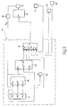
- Figure 2 shows an operating diagram of a hydraulic actuator of the Figure 1 clutch;
- Figure 3 shows a block diagram of the control unit controlling the power clutch in Figure 1.
- Number 1 in Figure 1 indicates a vehicle comprising a front internal combustion engine 2, which comprises a drive shaft 3 and two rows 4 of four
cylinders 5 each. In actual use, engine 2 produces on drive shaft 3 a drive torque which is transmitted to the road surface by a transmission train 6 to move vehicle 1. - Transmission train 6 comprises a power clutch 7, which is housed in a housing 8 integral with engine 2, and connects drive shaft 3 to a propeller shaft 9 terminating in a mechanical power-assisted gearbox 10 at the rear axle. A
differential 11 is cascade-connected to gearbox 10, and from which extend twoaxle shafts 12, each integral with a respectiverear drive wheel 13. - Clutch 7 comprises two
disks 14 respectively integral with drive shaft 3 and propeller shaft 9, and which are movable with respect to each, by a knownhydraulic actuator 15, between a closed position (clutch engaged), in which the twodisks 14 contact to transmit the drive torque from drive shaft 3 to propeller shaft 9, and an open position (clutch released), in which the twodisks 14 are detached to disconnect drive shaft 3 and propeller shaft 9. - Gearbox 10 has a
hydraulic actuator 16 for varying, in known manner, the gear ratio of gearbox 10 by varying the position of a secondary shaft (not shown), angularly integral withdifferential 11, with respect to the position of a primary shaft (not shown) angularly integral with propeller shaft 9. -
Hydraulic actuators central control unit 17 by means of a series of solenoid valves (not shown in detail in Figure 1). To perform its control function,central control unit 17 is connected to a series of sensors (not shown in detail in Figure 1) to acquire both driver commands and the values of various system reference quantities. - As shown in Figure 2,
hydraulic actuator 15 controlling clutch 7 is controlled bycentral control unit 17 by means of ahydraulic circuit 18, which is also partly used to controlhydraulic actuator 16 and for this reason is substantially located at the rear axle and fitted to gearbox 10. -
Hydraulic circuit 18 is filled with oil, and comprises an atmospheric-pressure oil tank 19, from which extends apipe 20 fitted with apump 21 and anon-return valve 22 to supply pressurized oil to ahydraulic accumulator 23; andhydraulic accumulator 23 is connected by apipe 24 to an inlet of aproportional solenoid valve 25, from which extend apipe 26 terminating intank 19, and apipe 27 terminating in awork chamber 28 ofhydraulic actuator 15. More specifically,solenoid valve 25 is designed to isolatepipe 27, and thereforework chamber 28, frompipes hydraulic actuator 15 in a given position; is designed to connectpipe 27, and thereforework chamber 28, to pipe 24 to feed pressurized oil towork chamber 28 and movehydraulic actuator 15 in adirection 29; and is designed to connectpipe 27, and thereforework chamber 28, to conduit 26 to draw pressurized oil fromwork chamber 28 and movehydraulic actuator 15 in adirection 30opposite direction 29. -
Tank 19,hydraulic accumulator 23, andsolenoid valve 25 are located at the rear axle and fitted to gearbox 10; andpipe 27 extends from the rear axle and terminates inwork chamber 28 ofhydraulic actuator 15, which is housed inside housing 8 of clutch 7. More specifically,pipe 27 is defined by aflexible portion 31 connectingsolenoid valve 25 to a connectingblock 32 integral with housing 8 of clutch 7, and by arigid portion 33 connectingblock 32 towork chamber 28. -
Hydraulic accumulator 23 is fitted with asensor 34 connected tocentral control unit 17 and for real-time determining the actual value Pp of the oil pressure insidehydraulic accumulator 23; and connectingblock 32 is fitted with asensor 35 connected tocentral control unit 17 and for real-time determining the actual value Put of the oil pressure insiderigid portion 33 ofpipe 27. It should be pointed out that, given the short length (roughly 25-35 cm) ofrigid portion 33, the value of the oil pressure insiderigid portion 33 practically equals the value of the oil pressure insidework chamber 28 ofhydraulic actuator 15. Finally,hydraulic actuator 15 is fitted with apotentiometer 36 connected tocentral control unit 17 and for real-time determining the position of hydraulic actuator 15 (and therefore of clutch 7, which is mechanically integral with hydraulic actuator 15). - As shown in Figure 3,
central control unit 17 employs areference generator 37, which generates a target value Pos* of the position ofhydraulic actuator 15, a target value Vel* of the speed of hydraulic actuator 15 (i.e. the derivative prior to target value Pos*, and a target value Acc* of the acceleration of hydraulic actuator 15 (i.e. the derivative prior to target value Pos*). More specifically,reference generator 37 generates the desired values according to known control methods and as a function of both drive-entered commands and the operating conditions of vehicle 1. - Target value Vel* of the speed of
hydraulic actuator 15, and target value Acc* of the acceleration ofhydraulic actuator 15 are supplied byreference generator 37 to acomputing block 38, which also receives the actual value Pos of the position of hydraulic actuator 15 (and therefore of clutch 7 mechanically integral with hydraulic actuator 15) determined in real time bypotentiometer 36. And, on the basis of the Pos, Vel* and Acc* values,computing block 38 calculates a forecast value P1 predicting the future value Put of the oil pressure insidework chamber 28. -
Central control unit 17 also employs adifferential block 39, which calculates the value Err of the error in the position of hydraulic actuator 15 (i.e. the difference between the target value Pos* and the actual value Pos of the position of hydraulic actuator 15). - The forecast value P1, the target value Pos* of the position of
hydraulic actuator 15, and the actual value Pos of the position ofhydraulic actuator 15 are supplied to aBode regulator 40, which, on the basis of values P1, Pos* and Pos, determines a target value Put* of the oil pressure insidework chamber 28. In other words,Bode regulator 40 determines the target value Put* of the oil pressure insidework chamber 28 required for the actual value Pos of the position ofhydraulic actuator 15 to match the target value Pos* of the position ofhydraulic actuator 15. - Finally,
central control unit 17 employs acontroller 41 for generating the target value I* of the current circulating in the electric actuator (not shown in detail) ofsolenoid valve 25. More specifically, the electric actuator ofsolenoid valve 25 implements feedback control of the current circulating through the electric actuator itself. -
Controller 41 receives the target value Put* of the oil pressure insidework chamber 28, the value Err of the error in the position ofhydraulic actuator 15, the target value Vel* of the speed ofhydraulic actuator 15, the actual value Put of the oil pressure insidework chamber 28, as determined bysensor 35, the actual value Pp of the oil pressure insidehydraulic accumulator 23, as determined bysensor 34, and the actual value Pt of the oil pressure inside tank 19 (not sensor-detected, but considered substantially constant and equal to atmospheric pressure). It is important to note that the actual oil pressure value Pp is the pressure value of the oil supplied towork chamber 28, while oil pressure value Pt is the pressure value of the oil drained fromwork chamber 28. - As will be clear from the foregoing description, three feedback control loops are employed to control the position of hydraulic actuator 15 (i.e. of clutch 7), i.e. to control the actual value Pos of the position of
hydraulic actuator 15. A first feedback control loop is controlled by Boderegulator 40, employs the actual value Pos of the position ofhydraulic actuator 15 as the feedback variable, and supplies the target value Put* of the oil pressure insidework chamber 28. A second feedback control loop is controlled bycontroller 41, employs the actual value Put of the oil pressure insidework chamber 28 as the feedback variable, and supplies the target value I* of the current circulating in the electric actuator ofsolenoid valve 25. And a third feedback control loop is controlled by the actuator ofsolenoid valve 25, and employs the measured current circulating through the actuator as the feedback variable. - Tests have shown that, by virtue of
sensor 35 for determining the actual value Put of the oil pressure insidework chamber 28,central control unit 17 is capable of ensuring optimum control of the position of clutch 7 in any operating condition.
Claims (10)
- A method of controlling a clutch (7) powered by a hydraulic actuator (15) comprising a work chamber (28), which is filled with a fluid and connected to a solenoid valve (25) for selective connection to a drain tank (19) for draining the fluid, or to a storage tank (23) for accumulating pressurized fluid; the method comprising the steps of:generating a target value (Pos*) of the position of the hydraulic actuator (15);measuring an actual value (Pos) of the position of the hydraulic actuator (15); andcalculating a control signal (I*) for controlling the solenoid valve (25) by feedback control of the position of the hydraulic actuator (15);the method is characterized by comprising the further steps of:calculating a forecast value (p1) predicting the value of the pressure of the fluid inside the work chamber (28),generating a target value (Put*) of the pressure of the fluid inside the work chamber (28) as a function of the actual value (Pos) of the position of the hydraulic actuator (15), of the target value (Pos*) of the position of the hydraulic actuator (15), and of the forecast value (P1) ;estimating an actual value (Put) of the pressure of the fluid inside the work chamber (28); andcalculating the control signal (I*) using both feedback control of the position of the hydraulic actuator (15), and feedback control of the pressure of the fluid inside the work chamber (28);
- A method as claimed in Claim 1, wherein the actual value (Put) of the pressure of the fluid inside the work chamber (28) is estimated by a pressure measurement inside the work chamber (28).
- A method as claimed in Claim 1, wherein the actual value (Put) of the pressure of the fluid inside the work chamber (28) is estimated by a pressure measurement inside a pipe (27) extending between the work chamber (28) and the solenoid valve (25) and connected permanently to the work chamber (28).
- A method as claimed in Claim 3, wherein the pressure measurement is made by a sensor (35) located inside the pipe (27) and close to the work chamber (28).
- A method as claimed in one of Claims 1 to 4, wherein a target value (Vel*) of the speed of the hydraulic actuator (15), and a target value (Acc*) of acceleration of the clutch are generated; the forecast value (P1) being generated as a function of the actual value (Pos) of the position of the hydraulic actuator (15), of the target value (Vel*) of the speed of the hydraulic actuator, and of the target value (Acc*) of acceleration of the clutch.
- A method as claimed in one of Claims 1 to 5, wherein a target value (Vel*) of the speed of the hydraulic actuator (15) is generated, an actual value (Pt) of the pressure of the fluid in the drain tank (19) is estimated, and an actual value (Pp) of the pressure of the fluid in the storage tank (23) is measured; the control signal (I*) being calculated as a function of the actual value (Put) of the pressure of the fluid inside the work chamber (28), of the target value (Put*) of the pressure of the fluid inside the work chamber (28), of the difference between the target value (Pos*) and actual value (Pos) of the position of the hydraulic actuator (15), of the target value (Vel*) of the speed of the hydraulic actuator, of the actual value (Pt) of the pressure of the fluid in the drain tank (19), and of the actual value (Pp) of the pressure of the fluid in the storage tank (23).
- A method as claimed in one of Claims 1 to 6, wherein the control signal (I*) represents a target value of the current circulating in an electric actuator of the solenoid valve (25); the electric actuator of the solenoid valve (25) implementing feedback control of the current circulating through the electric actuator itself.
- A control unit (17) for controlling a clutch (7) powered by a hydraulic actuator (15) comprising a work chamber (28), which is filled with a fluid and connected to a solenoid valve (25) for selective connection to a drain tank (19) for draining the fluid, or to a storage tank (23) for accumulating pressurized fluid; the control unit (17) comprising:a reference generator (37) for generating a target value (Pos*) of the position of the hydraulic actuator (15) ;a first sensor (36) for measuring an actual value (Pos) of the position of the hydraulic actuator (15); anda controller (41) for calculating a control signal (I*) for controlling the solenoid valve (25) by feedback control of the position of the hydraulic actuator (15);the control unit (17) is characterized by comprising:a computing block (38) for calculating a forecastvalue (P1) predicting the value of the pressure of the fluid inside the work chamber (28),a second sensor (35) for estimating an actual value (Put) of the pressure of the fluid inside the work chamber (28); anda regulator (40) for generating a target value (Put*) of the pressure of the fluid inside the work chamber (28) as a function of the actual value (Pos) of the position of the hydraulic actuator (15), of the target value (Pos*) of the position of the hydraulic actuator (15), and of the forecast value (P1);wherein the controller (41) is arranged such that it calculates the control signal (I*) using both feedback control of the position of the hydraulic actuator (15), and feedback control of the pressure of the fluid inside the work chamber (28).
- A cluster comprising control unit (17) as claimed in Claim 8, wherein the clutch is powered by a hydraulic actuator (15) comprising a work chamber (28), which is filled with a fluid and connected to a solenoid valve (25) for selective connection to a drain tank (19) for draining the fluid, or to a storage tank (23) for accumulating pressurized fluid, and wherein a pipe (27) extends between the work chamber (28) and the solenoid valve (25), is connected permanently to the work chamber (28), and houses the second sensor (35) close to the work chamber (28).
- A clutch as claimed in Claim 9, wherein the pipe (27) is defined by a flexible portion (31) connecting the solenoid valve (25) to a connecting block (32) integral with a housing (8) of the clutch (7), and by a rigid portion (33) connecting the connecting block (32) to the work chamber (28).
Applications Claiming Priority (2)
| Application Number | Priority Date | Filing Date | Title |
|---|---|---|---|
| ITBO20030002 | 2003-01-02 | ||
| IT000002A ITBO20030002A1 (en) | 2003-01-02 | 2003-01-02 | METHOD AND UNIT FOR CHECKING A CLUTCH |
Publications (2)
| Publication Number | Publication Date |
|---|---|
| EP1435469A1 EP1435469A1 (en) | 2004-07-07 |
| EP1435469B1 true EP1435469B1 (en) | 2006-05-24 |
Family
ID=32500544
Family Applications (1)
| Application Number | Title | Priority Date | Filing Date |
|---|---|---|---|
| EP03104994A Expired - Lifetime EP1435469B1 (en) | 2003-01-02 | 2003-12-30 | Method and unit for controlling a clutch powered by a hydraulic actuator |
Country Status (6)
| Country | Link |
|---|---|
| US (1) | US6918478B2 (en) |
| EP (1) | EP1435469B1 (en) |
| JP (1) | JP2004211892A (en) |
| DE (1) | DE60305426T2 (en) |
| ES (1) | ES2263918T3 (en) |
| IT (1) | ITBO20030002A1 (en) |
Families Citing this family (6)
| Publication number | Priority date | Publication date | Assignee | Title |
|---|---|---|---|---|
| DE102007009542B4 (en) * | 2007-02-27 | 2008-12-04 | Knorr-Bremse Systeme für Nutzfahrzeuge GmbH | Method for controlling a pressure medium consumer using a pressure difference sensor and control device |
| DE102007033825B4 (en) * | 2007-07-18 | 2021-05-20 | Nippon Steel & Sumikin Engineering Co., Ltd. | Roller grate with hydraulic drive and a method for operating the roller grate |
| DE102009018793A1 (en) * | 2009-04-24 | 2010-10-28 | Daimler Ag | transmission device |
| ITBO20120084A1 (en) | 2012-02-22 | 2013-08-23 | Magneti Marelli Spa | HYDRAULIC SERVO OF A SERVO-CHANGE |
| DE102012006355B4 (en) | 2012-03-28 | 2018-04-05 | Audi Ag | Transmission control device, motor vehicle with a transmission control device and method for operating a transmission control device |
| CN110475908B (en) | 2017-03-31 | 2022-10-14 | 美铝美国公司 | System and method for electrolytic production of aluminum |
Family Cites Families (8)
| Publication number | Priority date | Publication date | Assignee | Title |
|---|---|---|---|---|
| DE2301404A1 (en) * | 1973-01-12 | 1974-07-18 | Bernhard Mlakar | DEVICE FOR ANALYZING HANDWRITING |
| US5337874A (en) * | 1993-03-19 | 1994-08-16 | Eaton Corporation | Method/system for determining clutch touch point |
| US5404301A (en) * | 1993-06-07 | 1995-04-04 | Eaton Corporation | Method and apparatus of vehicle transmission control by assured minimum pulse width |
| US5393274A (en) * | 1993-07-19 | 1995-02-28 | Eaton Corporation | Touch point identification algorithm for automatic clutch controller |
| GB2296046B (en) * | 1994-10-18 | 1998-07-15 | Automotive Products Plc | Actuation systems |
| DE19516404A1 (en) * | 1995-05-04 | 1996-11-14 | Fichtel & Sachs Ag | Pressure actuated actuator |
| JP3609713B2 (en) * | 2000-11-07 | 2005-01-12 | 本田技研工業株式会社 | Control device for vehicle start clutch |
| GB2379721A (en) * | 2001-09-12 | 2003-03-19 | Luk Lamellen & Kupplungsbau | Automated transmission system |
-
2003
- 2003-01-02 IT IT000002A patent/ITBO20030002A1/en unknown
- 2003-12-25 JP JP2003430079A patent/JP2004211892A/en active Pending
- 2003-12-30 EP EP03104994A patent/EP1435469B1/en not_active Expired - Lifetime
- 2003-12-30 ES ES03104994T patent/ES2263918T3/en not_active Expired - Lifetime
- 2003-12-30 DE DE60305426T patent/DE60305426T2/en not_active Expired - Lifetime
- 2003-12-31 US US10/748,220 patent/US6918478B2/en not_active Expired - Lifetime
Also Published As
| Publication number | Publication date |
|---|---|
| ES2263918T3 (en) | 2006-12-16 |
| ITBO20030002A1 (en) | 2004-07-03 |
| DE60305426T2 (en) | 2006-12-07 |
| US6918478B2 (en) | 2005-07-19 |
| JP2004211892A (en) | 2004-07-29 |
| DE60305426D1 (en) | 2006-06-29 |
| EP1435469A1 (en) | 2004-07-07 |
| US20040216977A1 (en) | 2004-11-04 |
Similar Documents
| Publication | Publication Date | Title |
|---|---|---|
| US4805750A (en) | Steady state slip detection/correction for a motor vehicle transmission | |
| KR100270744B1 (en) | Yawing moment control method of vehicle and its control device | |
| EP1433982B1 (en) | Closed loop control of shifting clutch actuators in an automatic speed change transmission | |
| US5417622A (en) | Apparatus for controlling lock-up clutch | |
| EP2500224B1 (en) | Transmission turbine acceleration control for managing vehicle acceleration | |
| EP2166256B1 (en) | An agricultural vehicle with a continuously variable transmission | |
| EP0310275B1 (en) | Failure mode shift pattern alteration for an electronically controlled transmission | |
| EP0516309B1 (en) | Clutches | |
| KR100192606B1 (en) | Devices for controlling the operating pressure of the actuator for operating the frictional connection | |
| US5129286A (en) | Engine torque management for engine speed flare suppression for clutch-to-clutch-upshifting | |
| EP0235892A1 (en) | Clutch-to-clutch power-on downshifting in a motor vehicle automatic transmission | |
| EP0234685A2 (en) | Clutch upshift control | |
| US7693635B2 (en) | Method for learning the flow rate of hydraulic fluid in an automatic transmission | |
| US6918478B2 (en) | Method and unit for controlling a clutch powered by a hydraulic actuator | |
| US5493928A (en) | Transmission control default operation | |
| US6112870A (en) | Clutch pressure control apparatus and method for a working vehicle | |
| EP1176328B1 (en) | Vehicle clutch control device | |
| EP2065624B1 (en) | A method of driving an hydraulic actuator by means of a pressure-controlled proportioning solenoid valve | |
| CN114729693B (en) | Method and control unit for releasing a tooth-to-tooth position of a positive-locking shifting element of an automated shifting transmission | |
| EP1176329B1 (en) | Device for controlling a clutch for motor vehicles | |
| JP3968146B2 (en) | Hydraulic clutch control method and apparatus for ship propulsion device | |
| JPH05187537A (en) | Method of controlling adaptable pressure of automatic transmission | |
| JP4838071B2 (en) | Shifting operation structure of work vehicle | |
| EP3825476B1 (en) | Method for controlling the hydraulic aggressiveness of a work vehicle and work vehicle | |
| JP2007170416A (en) | Toroidal continuously variable tractor |
Legal Events
| Date | Code | Title | Description |
|---|---|---|---|
| PUAI | Public reference made under article 153(3) epc to a published international application that has entered the european phase |
Free format text: ORIGINAL CODE: 0009012 |
|
| AK | Designated contracting states |
Kind code of ref document: A1 Designated state(s): AT BE BG CH CY CZ DE DK EE ES FI FR GB GR HU IE IT LI LU MC NL PT RO SE SI SK TR |
|
| AX | Request for extension of the european patent |
Extension state: AL LT LV MK |
|
| 17P | Request for examination filed |
Effective date: 20050105 |
|
| 17Q | First examination report despatched |
Effective date: 20050208 |
|
| AKX | Designation fees paid |
Designated state(s): DE ES FR GB SE |
|
| GRAP | Despatch of communication of intention to grant a patent |
Free format text: ORIGINAL CODE: EPIDOSNIGR1 |
|
| RIN1 | Information on inventor provided before grant (corrected) |
Inventor name: FARACHI, FRANCESCO Inventor name: VISCONTI, AMEDEO Inventor name: TONIELLI, ALBERTO |
|
| GRAS | Grant fee paid |
Free format text: ORIGINAL CODE: EPIDOSNIGR3 |
|
| GRAA | (expected) grant |
Free format text: ORIGINAL CODE: 0009210 |
|
| AK | Designated contracting states |
Kind code of ref document: B1 Designated state(s): DE ES FR GB SE |
|
| REG | Reference to a national code |
Ref country code: GB Ref legal event code: FG4D |
|
| REF | Corresponds to: |
Ref document number: 60305426 Country of ref document: DE Date of ref document: 20060629 Kind code of ref document: P |
|
| REG | Reference to a national code |
Ref country code: SE Ref legal event code: TRGR |
|
| PGFP | Annual fee paid to national office [announced via postgrant information from national office to epo] |
Ref country code: SE Payment date: 20061018 Year of fee payment: 4 |
|
| REG | Reference to a national code |
Ref country code: ES Ref legal event code: FG2A Ref document number: 2263918 Country of ref document: ES Kind code of ref document: T3 |
|
| ET | Fr: translation filed | ||
| PGFP | Annual fee paid to national office [announced via postgrant information from national office to epo] |
Ref country code: ES Payment date: 20061229 Year of fee payment: 4 |
|
| PLBE | No opposition filed within time limit |
Free format text: ORIGINAL CODE: 0009261 |
|
| STAA | Information on the status of an ep patent application or granted ep patent |
Free format text: STATUS: NO OPPOSITION FILED WITHIN TIME LIMIT |
|
| 26N | No opposition filed |
Effective date: 20070227 |
|
| EUG | Se: european patent has lapsed | ||
| PG25 | Lapsed in a contracting state [announced via postgrant information from national office to epo] |
Ref country code: SE Free format text: LAPSE BECAUSE OF NON-PAYMENT OF DUE FEES Effective date: 20071231 |
|
| PGFP | Annual fee paid to national office [announced via postgrant information from national office to epo] |
Ref country code: FR Payment date: 20061023 Year of fee payment: 4 |
|
| REG | Reference to a national code |
Ref country code: FR Ref legal event code: ST Effective date: 20081020 |
|
| REG | Reference to a national code |
Ref country code: ES Ref legal event code: FD2A Effective date: 20071231 |
|
| PG25 | Lapsed in a contracting state [announced via postgrant information from national office to epo] |
Ref country code: FR Free format text: LAPSE BECAUSE OF NON-PAYMENT OF DUE FEES Effective date: 20071231 Ref country code: ES Free format text: LAPSE BECAUSE OF NON-PAYMENT OF DUE FEES Effective date: 20071231 |
|
| PGFP | Annual fee paid to national office [announced via postgrant information from national office to epo] |
Ref country code: GB Payment date: 20221220 Year of fee payment: 20 |
|
| PGFP | Annual fee paid to national office [announced via postgrant information from national office to epo] |
Ref country code: DE Payment date: 20221227 Year of fee payment: 20 |
|
| P01 | Opt-out of the competence of the unified patent court (upc) registered |
Effective date: 20230525 |
|
| REG | Reference to a national code |
Ref country code: DE Ref legal event code: R071 Ref document number: 60305426 Country of ref document: DE |
|
| PG25 | Lapsed in a contracting state [announced via postgrant information from national office to epo] |
Ref country code: GB Free format text: LAPSE BECAUSE OF EXPIRATION OF PROTECTION Effective date: 20231229 |
|
| REG | Reference to a national code |
Ref country code: GB Ref legal event code: PE20 Expiry date: 20231229 |
|
| PG25 | Lapsed in a contracting state [announced via postgrant information from national office to epo] |
Ref country code: GB Free format text: LAPSE BECAUSE OF EXPIRATION OF PROTECTION Effective date: 20231229 |