EP1435443A2 - Exhaust cleaning device of an internal combustion engine - Google Patents
Exhaust cleaning device of an internal combustion engine Download PDFInfo
- Publication number
- EP1435443A2 EP1435443A2 EP03028644A EP03028644A EP1435443A2 EP 1435443 A2 EP1435443 A2 EP 1435443A2 EP 03028644 A EP03028644 A EP 03028644A EP 03028644 A EP03028644 A EP 03028644A EP 1435443 A2 EP1435443 A2 EP 1435443A2
- Authority
- EP
- European Patent Office
- Prior art keywords
- engine
- particulate matter
- regeneration
- filter
- regeneration processing
- Prior art date
- Legal status (The legal status is an assumption and is not a legal conclusion. Google has not performed a legal analysis and makes no representation as to the accuracy of the status listed.)
- Granted
Links
Images


Classifications
-
- F—MECHANICAL ENGINEERING; LIGHTING; HEATING; WEAPONS; BLASTING
- F02—COMBUSTION ENGINES; HOT-GAS OR COMBUSTION-PRODUCT ENGINE PLANTS
- F02D—CONTROLLING COMBUSTION ENGINES
- F02D41/00—Electrical control of supply of combustible mixture or its constituents
- F02D41/02—Circuit arrangements for generating control signals
- F02D41/021—Introducing corrections for particular conditions exterior to the engine
- F02D41/0235—Introducing corrections for particular conditions exterior to the engine in relation with the state of the exhaust gas treating apparatus
- F02D41/027—Introducing corrections for particular conditions exterior to the engine in relation with the state of the exhaust gas treating apparatus to purge or regenerate the exhaust gas treating apparatus
- F02D41/029—Introducing corrections for particular conditions exterior to the engine in relation with the state of the exhaust gas treating apparatus to purge or regenerate the exhaust gas treating apparatus the exhaust gas treating apparatus being a particulate filter
-
- F—MECHANICAL ENGINEERING; LIGHTING; HEATING; WEAPONS; BLASTING
- F02—COMBUSTION ENGINES; HOT-GAS OR COMBUSTION-PRODUCT ENGINE PLANTS
- F02D—CONTROLLING COMBUSTION ENGINES
- F02D41/00—Electrical control of supply of combustible mixture or its constituents
- F02D41/02—Circuit arrangements for generating control signals
- F02D41/04—Introducing corrections for particular operating conditions
- F02D41/08—Introducing corrections for particular operating conditions for idling
-
- F—MECHANICAL ENGINEERING; LIGHTING; HEATING; WEAPONS; BLASTING
- F01—MACHINES OR ENGINES IN GENERAL; ENGINE PLANTS IN GENERAL; STEAM ENGINES
- F01N—GAS-FLOW SILENCERS OR EXHAUST APPARATUS FOR MACHINES OR ENGINES IN GENERAL; GAS-FLOW SILENCERS OR EXHAUST APPARATUS FOR INTERNAL-COMBUSTION ENGINES
- F01N3/00—Exhaust or silencing apparatus having means for purifying, rendering innocuous, or otherwise treating exhaust
- F01N3/02—Exhaust or silencing apparatus having means for purifying, rendering innocuous, or otherwise treating exhaust for cooling, or for removing solid constituents of, exhaust
- F01N3/021—Exhaust or silencing apparatus having means for purifying, rendering innocuous, or otherwise treating exhaust for cooling, or for removing solid constituents of, exhaust by means of filters
-
- F—MECHANICAL ENGINEERING; LIGHTING; HEATING; WEAPONS; BLASTING
- F02—COMBUSTION ENGINES; HOT-GAS OR COMBUSTION-PRODUCT ENGINE PLANTS
- F02D—CONTROLLING COMBUSTION ENGINES
- F02D41/00—Electrical control of supply of combustible mixture or its constituents
- F02D41/02—Circuit arrangements for generating control signals
- F02D41/04—Introducing corrections for particular operating conditions
- F02D41/12—Introducing corrections for particular operating conditions for deceleration
- F02D41/123—Introducing corrections for particular operating conditions for deceleration the fuel injection being cut-off
-
- F—MECHANICAL ENGINEERING; LIGHTING; HEATING; WEAPONS; BLASTING
- F02—COMBUSTION ENGINES; HOT-GAS OR COMBUSTION-PRODUCT ENGINE PLANTS
- F02D—CONTROLLING COMBUSTION ENGINES
- F02D41/00—Electrical control of supply of combustible mixture or its constituents
- F02D41/30—Controlling fuel injection
- F02D41/38—Controlling fuel injection of the high pressure type
- F02D41/40—Controlling fuel injection of the high pressure type with means for controlling injection timing or duration
- F02D41/401—Controlling injection timing
-
- F—MECHANICAL ENGINEERING; LIGHTING; HEATING; WEAPONS; BLASTING
- F02—COMBUSTION ENGINES; HOT-GAS OR COMBUSTION-PRODUCT ENGINE PLANTS
- F02D—CONTROLLING COMBUSTION ENGINES
- F02D41/00—Electrical control of supply of combustible mixture or its constituents
- F02D41/30—Controlling fuel injection
- F02D41/38—Controlling fuel injection of the high pressure type
- F02D41/40—Controlling fuel injection of the high pressure type with means for controlling injection timing or duration
- F02D41/402—Multiple injections
- F02D41/405—Multiple injections with post injections
Definitions
- the present invention relates to an internal combustion engine exhaust cleaning device provided with a particulate matter filter that collects particulate matter (PM), i.e., substances made up of particles, from exhaust gas in an exhaust passage. More particularly, the present invention relates to a technology for regenerating such a particulate matter filter.
- PM particulate matter
- one object of the present invention is to make it possible to suppress sharp rises in the filter temperature when the engine shifts into idling operation during regeneration of the particulate matter filter.
- the present invention is configured such that when regeneration of the particulate matter filter is in progress, the idling speed of the engine is raised above the normal idling speed that is used when regeneration is not in progress.
- the present invention suppresses the reduction in exhaust gas flow rate and secures the required gas cooling, thus enabling a sharp rise in filter temperature to be suppressed.
- an engine exhaust cleaning device that basically comprises a particulate matter filter, a regeneration processing section and an idling speed raising section.
- the particulate matter filter is configured to collects particulate matter from exhaust gas in an exhaust passage.
- the regeneration processing section is configured to execute regeneration processing that raises temperature of the particulate matter filter to remove the particulate matter collected in the particulate matter filter by combustion of the particulate matter collected in the particulate matter filter.
- the idling speed raising section is configured to raise the engine idling speed when the engine idles during the regeneration processing of the particulate matter filter by the regeneration processing section.
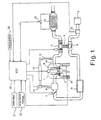
- Figure 1 is a schematic system diagram for a diesel engine equipped with an exhaust gas cleaning device in accordance with one embodiment of the present invention
- FIG 2 is a flowchart showing a diesel particulate filter regeneration control routine for the diesel particulate filter used in the diesel engine illustrated in Figure 1 in accordance with the present invention
- Figure 3 is a flowchart of the deceleration and idling control processes that are executed during regeneration of the diesel particulate filter by the exhaust gas cleaning device in accordance with the present invention.
- Figure 4 is a time chart illustrating a case in which the vehicle decelerates and the engine shifts into idling operation during regeneration of the diesel particulate filter by the exhaust gas cleaning device in accordance with the present invention.
- a schematic diagram of a direct injection diesel engine 1 is illustrated in accordance with a first embodiment of the present invention.
- the diesel engine 1 is preferable used in an automobile.
- the diesel engine 1 is well known in the art. Since diesel engines are well known in the art, the precise structure of the diesel engine 1 will not be discussed or illustrated in detail herein.
- the diesel engine 1 includes an engine block with a plurality of combustion chambers 2 formed by pistons that are movably mounted in cylinders of the engine block. Air is taken into the combustion chambers 2 of the cylinders of the diesel engine 1 after passing through an air cleaner 3 of the air intake system.
- the air intake system has a variable nozzle supercharger 4, an air compressor 5 driven by the variable nozzle supercharger 4, an intercooler 6, a throttle valve 7, and an air intake manifold 8.
- the fuel supply system is provided with a plurality of fuel injection valves 9 into which high-pressure fuel is directed from a common rail (not shown) and from which fuel can be injected into the combustion chambers 2 of the cylinders at any desired timing.
- Fuel is injected (main injection) during the compression stroke of each cylinder and combusted by compression ignition. After combustion, the exhaust gas is discharged through an exhaust manifold 10 of the exhaust system and an exhaust turbine 11 driven by the variable nozzle supercharger 4. A portion of the exhaust gas is drawn from the exhaust manifold 10 into an EGR passage 12 and passes through an EGR cooler 13 and an EGR valve 14 before being recirculated into the intake manifold 8.
- an exhaust gas cleaning device that includes a diesel particulate filter (DPF) 15 for collecting particulate matter is provided in the exhaust passage downstream of the exhaust turbine 11.
- DPF diesel particulate filter
- the exhaust gas cleaning device can be used with particulate matter filters other than the diesel particulate filter 15 mentioned herein.
- the term "particulate matter filter” is a generic term that includes, but is not limited to, a diesel particulate filter.
- the exhaust gas cleaning device is also provided with a regenerating device, which comprises an electronic control unit or ECU 20 and a plurality of sensors.
- the regenerating device is configured and arranged to remove the particulate matter collected in the particulate matter filter 15 by combustion of the particulate matter collected in the particulate matter filter 15.
- the regenerating device regenerates the diesel particulate filter 15 by combustion of the particulate matter collected in the diesel particulate filter 15. More specifically, the regenerating device determines a prescribed regeneration timing and then executes the regeneration processing that raises temperature of the diesel particulate filter 15.
- the electronic control unit 20 which forms a part of the regenerating device of the exhaust gas cleaning device, detects if a prescribed regeneration timing has been reached based on an accumulated particulate matter quantity and/or various engine operating conditions. If the electronic control unit 20 determines that the prescribed regeneration timing has been reached, then the electronic control unit 20 initiates the regeneration process to regenerate the diesel particulate filter 15 by raising the temperature of the exhaust gas, which in turn raises the temperature of the diesel particulate filter 15 to combust the particulate matter collected in the diesel particulate filter 15.
- the diesel particulate filter 15 has a honeycomb monolith made of ceramic or the like.
- the basic structure of the diesel particulate filter 15 is well known in the art. Since diesel particulate filters are well known in the art, the precise structure of the diesel particulate filter 15 will not be discussed or illustrated in detail herein.
- the electronic control unit 20 preferably includes a microcomputer with a regenerative particulate filter control program that controls various engine components, including, but not limited to, the variable nozzle supercharger 4, the throttle valve 7, the fuel injectors 9 and the EGR valve 14 as discussed below.
- the electronic control unit 20 can also include other conventional components such as an input interface circuit, an output interface circuit, and storage devices such as a ROM (Read Only Memory) device and a RAM (Random Access Memory) device.
- the microcomputer of the electronic control unit 20 is programmed to control the regeneration of the particulate filter 12.
- the memory circuit stores processing results and control programs are run by the processor circuit.
- the electronic control unit 20 is operatively coupled to various sensors that are used to execute the regenerative processing of the diesel particulate filter 15.
- the internal RAM of the electronic control unit 20 stores statuses of operational flags and various control data.
- the internal ROM of the electronic control unit 20 stores various operations as needed and/or desired. It will be apparent to those skilled in the art from this disclosure that the precise structure and algorithms for electronic control unit 20can be any combination of hardware and software that will carry out the functions of the present invention. In other words, "means plus function" clauses as utilized in the specification and claims should include any structure or hardware and/or algorithm or software that can be utilized to carry out the function of the "means plus function” clause.
- the processing steps of the electronic control unit 20 that carry out the function of the regeneration process constitute a regeneration processing device or section (i.e., a device for raising the temperature of the diesel particulate filter 15. More specifically, this regeneration processing device or section raises the temperature of the exhaust gas flowing into the diesel particulate filter 15 to raise the temperature of the diesel particulate filter 15.
- the particulate matter can be combusted by controlling one or more of the following engine operating conditions: (1) retarding the fuel injection timing (main fuel injection) of the fuel injection valves 9; (2) executing a post injection that comprises an additional injection of fuel from the fuel injection valves 9 during the power stroke or the exhaust stroke; (3) reducing the opening degree of the throttle valve 7 (reduced intake air quantity leads to a richer fuel-air mixture and a higher exhaust gas temperature); (4) reducing the supercharging pressure of the variable nozzle supercharger 4 (reduced intake air quantity leads to a richer fuel-air mixture and a higher exhaust gas temperature); and/or (5) increasing the EGR rate of the EGR valve 14.
- the engine control unit 20 that controls the operation of the fuel injection valves 9, the throttle valve 7, the variable nozzle supercharger 4, and the EGR valve 14 receives one or more control signals from the following items: (1) a crank angle sensor 21 that generates a crank angle signal that is synchronized with the engine rotation and can be used to detect the engine speed; (2) an accelerator position sensor 22 (which includes an idle switch that turns ON when the accelerator is OFF) that detects the accelerator position (accelerator pedal depression amount); (3) an air flow meter 23 that detects the intake air quantity; (4) a coolant temperature sensor 24 that detects the temperature of the engine coolant; (5) a vehicle speed sensor 25 that detects the vehicle speed; and (6) a pressure difference sensor 26 that detects the pressure at the front and rear of the diesel particulate filter 15 in order to detect the pressure loss across the diesel particulate filter 15.
- a crank angle sensor 21 that generates a crank angle signal that is synchronized with the engine rotation and can be used to detect the engine speed
- an accelerator position sensor 22 which includes an idle
- crank angle sensor 21 can be used to detect the engine speed and the accelerator position sensor 22 that detects the accelerator position (accelerator pedal depression amount) can be used to estimate load
- the sensor 21 and 22 together with the processing of the engine control unit 20 form an exhaust gas flow rate detecting section configured to detect or estimate an exhaust gas flow rate flowing through the diesel particulate filter 15.
- the engine control unit 20 detects the pressure difference across the diesel particulate filter 15 based on the signal from a pressure difference sensor 26. Thus, the engine control unit 20 estimates the accumulated quantity of particulate matter (PM) based on the detected pressure difference. The engine control unit 20 determines the regeneration timing based on the estimated accumulated particulate matter quantity and executes regeneration processing when the engine control unit 20 determines that the regeneration timing has been reached.
- PM particulate matter
- the flowchart of Figure 2 illustrates the regeneration processing by the engine control unit 20 for executing the diesel particulate filter regeneration control routine, which is repeated each time that a prescribed amount of time elapses.
- step S1 the engine control unit 20 reads in the signal from the pressure difference sensor 26 and determines the pressure difference across the diesel particulate filter 15.
- step S2 the engine control unit 20 refers to a table for estimating the accumulated particulate matter quantity from the diesel particulate filter (DPF) pressure difference, and thus, the engine control unit 20 estimates the accumulated particulate matter quantity based on the diesel particulate filter pressure difference detected in step S1.
- the diesel particulate filter pressure difference also varies depending on the exhaust gas flow rate.
- it is preferred to detect the engine speed and load i.e., using one or more control signals from the sensors 21 and 21
- the engine control unit 20 adjusts the estimated accumulated particulate matter quantity in accordance with the estimated exhaust gas flow rate.
- step S3 the engine control unit 20 checks the value of the regeneration flag and proceeds to step S4 if the regeneration flag is 0 (regeneration not in progress).
- step S4 the engine control unit 20 compares the accumulated particulate matter quantity estimated in step S2 with a prescribed value M1 for determining if the accumulated particulate matter quantity is greater than or equal to M1.
- the prescribed value M1 is used for determining the regeneration timing for initiating regeneration of the diesel particulate filter 15.
- the engine control unit 20 determines that it is not time to regenerate the diesel particulate filter 15 and returns to the beginning of the control routine. If the accumulated particulate matter quantity is greater than or equal to M1, the engine control unit 20 determines that it is time to regenerate the diesel particulate filter 15 (regeneration required) and proceeds to step S5.
- step S5 the engine control unit 20 determines if the current operating conditions satisfy the regeneration execution conditions (i.e., if the engine operating state is such that regeneration is possible). If the regeneration execution conditions are satisfied (e.g., if the engine is not idling and the engine is operating at somewhat high-speed or high-load conditions or the vehicle speed is high), the engine control unit 20 proceeds to step S6 to start regeneration processing.
- This section or step (step S5) and the prior section or step (step S4) of the processing by the engine control unit 20 correspond to the regeneration timing determining device or section of the present invention.
- step S6 the engine control unit 20 sets the regeneration flag to 1 and proceeds to step S7.
- the engine control unit 20 will obtain a result of "Yes" in step S3 and proceed directly from step S3 to step S7 because the regeneration flag will have a value of 1.
- step S7 in order to regenerate the diesel particulate filter 15, the engine control unit 20 executes regeneration processing that serves to raise the temperature of the diesel particulate filter 15 (i.e., raises the temperature of the exhaust gas flowing into the diesel particulate filter 15) and thus, remove the particulate matter accumulated in the diesel particulate filter 15 by combusting the particulate matter accumulated in the diesel particulate filter 15. More specifically, the temperature of the exhaust gas is raised such that the temperature inside the diesel particulate filter 15 rises to a temperature from which the particulate matter can be combusted such that the particulate matter accumulated in the diesel particulate filter 15 is removed by combustion.
- regeneration processing serves to raise the temperature of the diesel particulate filter 15 (i.e., raises the temperature of the exhaust gas flowing into the diesel particulate filter 15) and thus, remove the particulate matter accumulated in the diesel particulate filter 15 by combusting the particulate matter accumulated in the diesel particulate filter 15. More specifically, the temperature of the exhaust gas
- the temperature of the exhaust gas is raised by controlling one or more engine components such as retarding the fuel injection timing (main fuel injection) of the fuel injection valves 9, executing a post injection that comprises an additional injection of fuel from the fuel injection valves 9 during the power stroke or the exhaust stroke, reducing the opening degree of the throttle valve 7, reducing the supercharging pressure of the variable nozzle supercharger 4, and/or increasing the EGR rate of the EGR valve 14.
- this regeneration processing it is preferred for the engine control unit 20 to set a target regeneration processing temperature and, based on the target regeneration processing temperature, set or feedback control the fuel injection timing (main injection timing), the post injection timing/quantity, the throttle value opening degree, the supercharging pressure, and/or the EGR rate.
- step S8 in order to determine if prescribed regeneration ending conditions (complete regeneration conditions) are satisfied, the engine control unit 20 compares the latest accumulated particulate matter quantity with a prescribed value M2 (M2 ⁇ M1) used for determining complete regeneration and determines if the accumulated particulate matter quantity is less than or equal to M2.
- M2 M2 ⁇ M1
- the engine control unit 20 determines that the regeneration is not complete and returns to the start of the control routine to continue the regeneration processing.
- step S8 If the accumulated particulate matter quantity is found to be less than or equal to M2 (or if the prescribed regeneration time period is found to have elapsed) in step S8, the engine control unit 20 determines that the regeneration is complete and proceeds to step S9.
- the sections or steps S8 and S4 of the processing by the engine control unit 20 correspond to a portion of the regeneration timing determining device or section of the present invention.
- step S9 the engine control unit 20 ends the regeneration processing. More specifically, the parameters whose values were changed in step S7 in order to execute regeneration processing are all returned to their original values. Then, in step S10, the engine control unit 20 resets the regeneration flag to 0 and returns to the start of the control routine.
- the sections or steps S3 - S10 of the processing by the engine control unit 20 correspond to the regeneration processing device or section of the present invention.
- Figure 3 the flowchart of Figure 3 illustrates the deceleration and idle control routine executed by the engine control unit 20, which is repeated in parallel with the routine of Figure 2 each time that a prescribed amount of time elapses.
- step S11 the engine control unit 20 determines if the regeneration flag is set to 1 (i.e., if regeneration is in progress). If the regeneration flag is 0 (regeneration not in progress), the engine control unit 20 sets the fuel cut (F/C) recovery engine speed to the normal value in step S21 and sets the target engine idling speed to the normal value in step S22 before returning to the start of the routine.
- the regeneration flag is set to 1 (i.e., if regeneration is in progress). If the regeneration flag is 0 (regeneration not in progress), the engine control unit 20 sets the fuel cut (F/C) recovery engine speed to the normal value in step S21 and sets the target engine idling speed to the normal value in step S22 before returning to the start of the routine.
- F/C fuel cut
- step S12 the engine control unit 20 checks if deceleration has already been detected since regeneration started and proceeds to step S13 if deceleration has not already been detected.
- step S13 the engine control unit 20 determines if deceleration has occurred or is occurring. More specifically, it determines, for example, if the idle switch has changed from OFF to ON as determined by the accelerator position sensor 22. It is also acceptable to determining if deceleration has occurred or is occurring based on the amount of decline in the engine speed. If deceleration is determined to have occurred or is occurring, the engine control unit 20 executes steps S14 to S16.
- step S14 the fuel cut (F/C) recovery engine speed is set to a value higher than the normal value (i.e., value used when regeneration is not in progress).
- This section or step (step S14) of the processing by the engine control unit 20 corresponds to the fuel cut recovery engine speed increasing device or section of the present invention.
- step S15 the target engine idling speed is set to a value higher than the normal value (i.e., value used when regeneration is not in progress).
- This section or step (step S15) of the processing by the engine control unit 20 corresponds to the engine idling speed raising device or section of the present invention.
- step S16 the engine control unit 20 resets to 0 a timer TM for measuring the amount of time that idling has continued during regeneration and returns to the start of the routine.
- fuel cutting is triggered (i.e., fuel injection by the fuel injection valves 9 is stopped) when the idle switch is ON and the engine speed is greater than or equal to a prescribed fuel cut engine speed.
- fuel cut recovery (ending fuel cutting and resuming fuel injection) is executed when the accelerator turns ON (idling switch OFF) or when the engine speed becomes equal to or less than the fuel cut recovery engine speed.
- the engine control unit 20 compares the actual engine speed to the target engine idling speed during idling and executes feedback control of the fuel injection quantity of the fuel injection valves 9 (and/or the opening degree of the throttle valve 7) in such a manner that the target engine idling speed.
- the engine idling speed that results when the engine shifts from deceleration operation to idling operation during regeneration can be increased.
- the decrease in the exhaust gas flow rate can be suppressed and a sharp rise in the diesel particulate filter temperature can be prevented.
- step S17 After it has been determined that deceleration has occurred during regeneration, the engine control unit 20 will proceed to step S17 because it will obtain a result of "Yes" in step S12.
- step S17 the engine control unit 20 determines of the engine is idling. More specifically, it determines that the engine is idling when, for example, the idling switch is ON and the engine speed is within a prescribed range defined by the target engine idling speed.
- step S18 If the engine is not idling, the engine control unit 20 returns to the start of the routine. If the engine is idling, the engine control unit 20 proceeds to step S18.
- step S19 the engine control unit 20 determines if the value of the timer TM has exceeded a prescribed time period (several minutes).
- the engine control unit 20 If the amount of time that idling operation has continued is less than or equal to a prescribed amount of time, the engine control unit 20 returns to the start of the routine so that the increased idling speed can be continued by maintaining the increased target engine idling speed.
- step S20 the engine control unit 20 proceeds to step S20 where it returns the target engine idling speed to the normal value and ends the increased idling speed before returning to the start of the routine. Since there is no more risk of the exhaust gas temperature rising sharply, the engine idling speed is returned to normal to suppress degradation of the fuel economy.
- fuel cutting is executed until the engine speed decreases to a prescribed fuel cut (F/C) recovery engine speed and then fuel cut recovery is executed.
- F/C fuel cut
- the fuel cut recovery engine speed is increased to a value higher than the normal value. As a result, the engine speed can be held at a comparatively high speed when deceleration occurs while regeneration is in progress.
- the engine idling speed is feedback-controlled by increasing and decreasing the fuel injection quantity so that the engine speed matches the target engine idling speed.
- the target engine idling speed is increased to a value higher than the normal value for a prescribed amount of time after idling operation begins.
- the engine speed (idling speed) during idling operation can be maintained at a comparatively high speed.
- the engine speed is kept comparatively high and decreases in the exhaust gas flow rate are suppressed.
- a sharp rise in the temperature of the diesel particulate filter 15 can be prevented.
- the diesel particulate filter 15 can be regenerated reliably and quickly once regeneration has started because regeneration can be continued without interruption even if the vehicle decelerates and the engine shifts into idling operation.
Landscapes
- Engineering & Computer Science (AREA)
- Chemical & Material Sciences (AREA)
- Combustion & Propulsion (AREA)
- Mechanical Engineering (AREA)
- General Engineering & Computer Science (AREA)
- Processes For Solid Components From Exhaust (AREA)
- Electrical Control Of Air Or Fuel Supplied To Internal-Combustion Engine (AREA)
- Combined Controls Of Internal Combustion Engines (AREA)
Abstract
Description
Claims (7)
- An engine exhaust cleaning device comprising:a particulate matter filter (15) configured to collects particulate matter from exhaust gas in an exhaust passage (10);a regeneration processing section (Steps S3 - S 10) configured to execute regeneration processing that raises temperature of the particulate matter filter (15) to remove the particulate matter collected in the particulate matter filter (15) by combustion of the particulate matter collected in the particulate matter filter (15); andan idling speed raising section (Step S15) configured to raise the engine idling speed when the engine idles during the regeneration processing of the particulate matter filter (15) by the regeneration processing section (Steps S3 - S10).
- The engine exhaust cleaning device recited in claim 1, further comprising
a fuel cut recovery engine speed (Step S 14) processing section configured to raise a fuel cut recovery engine speed during the regeneration processing of the particulate matter filter (15) by the regeneration processing section (Steps S3 - S10). - The engine exhaust cleaning device recited in claim 1 or 2, wherein
the idling speed raising section (Step S15) is further configured to raise the engine idling speed for a prescribed amount of time when the engine idles during the regeneration processing of the particulate matter filter (15), and after the prescribed amount of time has elapsed, returns the engine idling speed to a normal idling speed value, when the engine idles during the regeneration processing of the particulate matter filter (15). - The engine exhaust cleaning device recited in any one of claims 1 to 3, wherein
the regeneration processing section (Steps S3 - S10) includes an accumulated particulate quantity detecting section (Steps S4 and S8) configured to detect the quantity of particulate matter that has accumulated within the particulate matter filter (15) to determine regeneration timing to regenerate the particulate matter filter (15) when an accumulated particulate quantity reaches a first prescribed quantity. - The engine exhaust cleaning device recited in claim 4, wherein the accumulated particulate quantity detecting section (Steps S4 and S8) includes
a filter pressure difference detecting sensor (26) configured to detect a pressure difference across the particulate matter filter (15),
an exhaust gas flow rate detecting section (21 and 22) configured to detect an exhaust gas flow rate, and
an accumulated particulate quantity computing section (Step S4) configured to compute the accumulated particulate quantity that has accumulated in the particulate matter filter (15) based on the filter pressure difference detected by the filter pressure difference detecting sensor and the exhaust gas flow rate detected by the exhaust gas flow rate detecting section (21 and 22), and
the regeneration processing section (Steps S3 - S10) is further configured to determine the regeneration timing to regenerate the particulate matter filter (15) by comparing the accumulated particulate quantity computed by the accumulated particulate quantity computing section (Step S4) with the first prescribed quantity. - The engine exhaust cleaning device recited in claim 4 or 5, wherein
the regeneration processing section (Steps S3 - S10) is further configured to end the regeneration processing of the particulate matter filter (15) by the regeneration processing section (Steps S3 - S10) by comparing the accumulated particulate quantity with a second prescribed quantity that is less than the first prescribed quantity. - The engine exhaust cleaning device recited in any one of claims 1 to 6, wherein
the regeneration processing section (Steps S3 - S10) is further configured to increase the temperature of the exhaust gas by adjusting at least one of the following: a timing of a main fuel injection used for controlling the engine torque, a timing and quantity of a post fuel injection executed after the main fuel injection, a cross sectional area of an air intake passage opening, a supercharging pressure produced by a supercharger, and a flow rate of exhaust gas recirculated from the an exhaust passage to an air intake passage.
Applications Claiming Priority (2)
| Application Number | Priority Date | Filing Date | Title |
|---|---|---|---|
| JP2002374873 | 2002-12-25 | ||
| JP2002374873A JP4228690B2 (en) | 2002-12-25 | 2002-12-25 | Exhaust gas purification device for internal combustion engine |
Publications (3)
| Publication Number | Publication Date |
|---|---|
| EP1435443A2 true EP1435443A2 (en) | 2004-07-07 |
| EP1435443A3 EP1435443A3 (en) | 2004-12-08 |
| EP1435443B1 EP1435443B1 (en) | 2007-02-14 |
Family
ID=32501119
Family Applications (1)
| Application Number | Title | Priority Date | Filing Date |
|---|---|---|---|
| EP03028644A Expired - Lifetime EP1435443B1 (en) | 2002-12-25 | 2003-12-15 | Exhaust cleaning device of an internal combustion engine |
Country Status (5)
| Country | Link |
|---|---|
| US (1) | US6978602B2 (en) |
| EP (1) | EP1435443B1 (en) |
| JP (1) | JP4228690B2 (en) |
| CN (1) | CN1304743C (en) |
| DE (1) | DE60311758T2 (en) |
Cited By (2)
| Publication number | Priority date | Publication date | Assignee | Title |
|---|---|---|---|---|
| FR2906301A1 (en) * | 2006-09-27 | 2008-03-28 | Renault Sas | METHOD AND DEVICE FOR MONITORING A DELEGATION SYSTEM AND VEHICLE PROVIDED WITH THE DEVICE |
| EP2690270A1 (en) * | 2012-07-24 | 2014-01-29 | Peugeot Citroën Automobiles Sa | Method for regenerating a particle filter fitted to an exhaust line of a motor vehicle |
Families Citing this family (52)
| Publication number | Priority date | Publication date | Assignee | Title |
|---|---|---|---|---|
| US20050155345A1 (en) * | 2002-03-29 | 2005-07-21 | Tokyo Electron Limited | Device and method for purifying exhaust gas from industrial vehicle engine |
| JP2006029239A (en) * | 2004-07-16 | 2006-02-02 | Toyota Motor Corp | Exhaust purification filter overheat prevention device |
| JP4525232B2 (en) * | 2004-08-06 | 2010-08-18 | 日産自動車株式会社 | Diesel engine exhaust aftertreatment system |
| JP4003768B2 (en) * | 2004-09-14 | 2007-11-07 | トヨタ自動車株式会社 | Exhaust gas purification system for internal combustion engine |
| JP4321445B2 (en) * | 2004-11-22 | 2009-08-26 | トヨタ自動車株式会社 | Control device for internal combustion engine |
| JP2006152891A (en) * | 2004-11-29 | 2006-06-15 | Denso Corp | Exhaust gas purification device for internal combustion engine |
| JP4595521B2 (en) * | 2004-12-16 | 2010-12-08 | 日産自動車株式会社 | Exhaust gas purification device for internal combustion engine |
| JP2007051586A (en) * | 2005-08-18 | 2007-03-01 | Toyota Industries Corp | Exhaust emission control device for diesel engine |
| JP4720476B2 (en) * | 2005-12-14 | 2011-07-13 | 日産自動車株式会社 | Exhaust gas filter regeneration control device and exhaust gas filter regeneration control method |
| EP2041406B2 (en) * | 2006-06-14 | 2021-03-03 | Volvo Lastvagnar AB | Method and system for regenerating an exhaust gas purification unit |
| US20080053074A1 (en) * | 2006-08-31 | 2008-03-06 | Caterpillar Inc. | Method and system for particulate filter regeneration |
| US8539759B2 (en) * | 2006-09-13 | 2013-09-24 | GM Global Technology Operations LLC | Regeneration control system for a particulate filter |
| JP4306722B2 (en) * | 2006-11-24 | 2009-08-05 | トヨタ自動車株式会社 | Fuel injection device |
| US7997069B2 (en) * | 2007-06-26 | 2011-08-16 | GM Global Technology Operations LLC | Ash reduction system using electrically heated particulate matter filter |
| US7684924B2 (en) * | 2007-07-02 | 2010-03-23 | Gm Global Technology Operations, Inc. | Thermal detection and protection of vehicle hardware |
| JP2009074426A (en) * | 2007-09-20 | 2009-04-09 | Toyota Motor Corp | Control device for internal combustion engine |
| JP5145542B2 (en) | 2007-11-26 | 2013-02-20 | ダイムラー・アクチェンゲゼルシャフト | Drive control device for hybrid vehicle |
| US8316638B2 (en) * | 2007-12-12 | 2012-11-27 | GM Global Technology Operations LLC | Control system for a particulate matter filter |
| JP5024066B2 (en) * | 2008-01-16 | 2012-09-12 | 株式会社デンソー | Exhaust gas purification device for internal combustion engine |
| US7987672B2 (en) * | 2008-01-22 | 2011-08-02 | GM Global Technology Operations LLC | Turbocharger protection systems and methods |
| DE102008014528A1 (en) * | 2008-03-15 | 2009-09-17 | Hjs Fahrzeugtechnik Gmbh & Co. Kg | Method for determining the loading state of a particle filter switched into the exhaust gas line of an internal combustion engine and device for reducing the particle emission of an internal combustion engine |
| US8322132B2 (en) * | 2008-04-30 | 2012-12-04 | Perkins Engines Company Limited | Exhaust treatment system implementing regeneration control |
| JP2010184183A (en) | 2009-02-11 | 2010-08-26 | Nippon Soken Inc | Exhaust emission control system |
| DE102009001538B4 (en) * | 2009-03-13 | 2013-07-04 | Ford Global Technologies, Llc | Method for operating a particle filter and particle filter |
| JP5651926B2 (en) * | 2009-04-25 | 2015-01-14 | 井関農機株式会社 | Agricultural machinery diesel engine |
| CN102472135B (en) * | 2009-07-02 | 2015-02-11 | 洋马株式会社 | Engine device |
| JP5614996B2 (en) * | 2010-01-28 | 2014-10-29 | 三菱重工業株式会社 | Exhaust gas treatment method and apparatus for internal combustion engine |
| US8424290B2 (en) * | 2010-02-26 | 2013-04-23 | GM Global Technology Operations LLC | Method and system for controlling an engine during diesel particulate filter regeneration at idle conditions |
| JP5440384B2 (en) * | 2010-05-25 | 2014-03-12 | いすゞ自動車株式会社 | Exhaust gas purification system |
| JP5548882B2 (en) * | 2010-08-27 | 2014-07-16 | 日立建機株式会社 | Exhaust gas purification system for work vehicles |
| US8857152B2 (en) * | 2010-12-21 | 2014-10-14 | GM Global Technology Operations LLC | System and method for unloading hydrocarbon emissions from an exhaust after-treatment device |
| US9371796B2 (en) * | 2011-01-07 | 2016-06-21 | Nissan Motor Co., Ltd. | Combustion control device and method for diesel engine |
| JP5235229B2 (en) * | 2011-07-04 | 2013-07-10 | 株式会社小松製作所 | Particulate removal filter regeneration control device and regeneration control method therefor |
| US20130086887A1 (en) * | 2011-10-07 | 2013-04-11 | Nathaniel D. Bergland | Method For Reducing The Rate Of Exhaust Heat Loss |
| JP5835462B2 (en) | 2012-03-14 | 2015-12-24 | 日産自動車株式会社 | Diesel engine control device and control method |
| DE102012015259A1 (en) * | 2012-08-01 | 2014-02-06 | Daimler Ag | Process for treating exhaust gas and arrangement of an exhaust system on an internal combustion engine |
| US9394837B2 (en) | 2012-08-13 | 2016-07-19 | Ford Global Technologies, Llc | Method and system for regenerating a particulate filter |
| WO2014055016A1 (en) * | 2012-10-02 | 2014-04-10 | Scania Cv Ab | Regulation of a temperature in an exhaust aftertreatment system |
| US9212614B2 (en) * | 2013-11-21 | 2015-12-15 | Cummins Inc. | Thermal management for regenerating an aftertreatment device |
| US9657664B2 (en) * | 2015-02-02 | 2017-05-23 | Ford Global Technologies, Llc | Method and system for maintaining a DFSO |
| GB2541199A (en) | 2015-08-11 | 2017-02-15 | Ford Global Tech Llc | A method of protecting a diesel particulate filter from overheating |
| KR101755934B1 (en) * | 2015-12-11 | 2017-07-07 | 현대자동차주식회사 | A method for protecting dpf in dti conditions and an apparastus therefor |
| JP6308259B2 (en) * | 2016-08-12 | 2018-04-11 | マツダ株式会社 | Diesel engine control method and control system |
| CN106401720B (en) * | 2016-11-30 | 2019-02-19 | 安徽江淮汽车集团股份有限公司 | A kind of method and system for preventing diesel particulate traps from crossing burning |
| WO2018200623A1 (en) * | 2017-04-28 | 2018-11-01 | Cummins Inc. | Methods and systems for removing deposits in an aftertreatment system to minimize visible smoke emissions |
| JP2019100323A (en) * | 2017-12-08 | 2019-06-24 | マツダ株式会社 | Control device for engine |
| JP6705439B2 (en) * | 2017-12-12 | 2020-06-03 | マツダ株式会社 | Engine controller |
| JP6486523B1 (en) * | 2018-03-13 | 2019-03-20 | 愛三工業株式会社 | Engine system |
| JP6486536B1 (en) | 2018-03-13 | 2019-03-20 | 愛三工業株式会社 | Gasoline engine system |
| DE102019108016B4 (en) * | 2019-03-28 | 2022-10-27 | Volkswagen Aktiengesellschaft | Process for regenerating a particle filter |
| JP7452500B2 (en) * | 2021-07-12 | 2024-03-19 | トヨタ自動車株式会社 | Vehicle control system |
| JP7722290B2 (en) * | 2022-07-27 | 2025-08-13 | トヨタ自動車株式会社 | Filter regeneration control device |
Family Cites Families (11)
| Publication number | Priority date | Publication date | Assignee | Title |
|---|---|---|---|---|
| US4535588A (en) * | 1979-06-12 | 1985-08-20 | Nippon Soken, Inc. | Carbon particulates cleaning device for diesel engine |
| US4567725A (en) * | 1983-01-10 | 1986-02-04 | Nissan Motor Company, Limited | Trap regenerative device control apparatus |
| JPS60206923A (en) * | 1984-03-31 | 1985-10-18 | Mitsubishi Motors Corp | Diesel particulates catching member protector |
| DE3580606D1 (en) * | 1984-03-31 | 1991-01-03 | Mitsubishi Motors Corp | REGENERATION SYSTEM FOR A DIESEL PARTICLE OXYDING DEVICE. |
| US5063736A (en) | 1989-08-02 | 1991-11-12 | Cummins Engine Company, Inc. | Particulate filter trap load regeneration system |
| JPH0658137A (en) | 1992-08-06 | 1994-03-01 | Nippon Soken Inc | Exhaust emission control device for internal combustion engine |
| US6304815B1 (en) | 2000-03-29 | 2001-10-16 | Ford Global Technologies, Inc. | Method for controlling an exhaust gas temperature of an engine for improved performance of exhaust aftertreatment systems |
| DE60126871T2 (en) | 2000-07-24 | 2007-11-15 | Toyota Jidosha Kabushiki Kaisha, Toyota | Exhaust gas purification device for an internal combustion engine |
| US6598387B2 (en) * | 2000-12-21 | 2003-07-29 | Ford Global Technologies, Llc | Reduction of exhaust smoke emissions following extended diesel engine idling |
| JP3829699B2 (en) * | 2001-11-28 | 2006-10-04 | いすゞ自動車株式会社 | Exhaust gas purification system and its regeneration control method |
| US6901751B2 (en) * | 2002-02-01 | 2005-06-07 | Cummins, Inc. | System for controlling particulate filter temperature |
-
2002
- 2002-12-25 JP JP2002374873A patent/JP4228690B2/en not_active Expired - Fee Related
-
2003
- 2003-11-05 US US10/700,517 patent/US6978602B2/en not_active Expired - Lifetime
- 2003-12-15 EP EP03028644A patent/EP1435443B1/en not_active Expired - Lifetime
- 2003-12-15 DE DE60311758T patent/DE60311758T2/en not_active Expired - Lifetime
- 2003-12-25 CN CNB2003101235788A patent/CN1304743C/en not_active Expired - Lifetime
Cited By (4)
| Publication number | Priority date | Publication date | Assignee | Title |
|---|---|---|---|---|
| FR2906301A1 (en) * | 2006-09-27 | 2008-03-28 | Renault Sas | METHOD AND DEVICE FOR MONITORING A DELEGATION SYSTEM AND VEHICLE PROVIDED WITH THE DEVICE |
| WO2008037901A1 (en) * | 2006-09-27 | 2008-04-03 | Renault S.A.S | Method and device for controlling an anti-pollution system, and vehicle provided with the device |
| EP2690270A1 (en) * | 2012-07-24 | 2014-01-29 | Peugeot Citroën Automobiles Sa | Method for regenerating a particle filter fitted to an exhaust line of a motor vehicle |
| FR2993931A1 (en) * | 2012-07-24 | 2014-01-31 | Peugeot Citroen Automobiles Sa | METHOD FOR REGENERATING A PARTICULATE FILTER EQUIPPED WITH AN EXHAUST LINE OF A MOTOR VEHICLE |
Also Published As
| Publication number | Publication date |
|---|---|
| CN1304743C (en) | 2007-03-14 |
| JP2004204774A (en) | 2004-07-22 |
| CN1510255A (en) | 2004-07-07 |
| JP4228690B2 (en) | 2009-02-25 |
| DE60311758D1 (en) | 2007-03-29 |
| US6978602B2 (en) | 2005-12-27 |
| EP1435443A3 (en) | 2004-12-08 |
| US20040123589A1 (en) | 2004-07-01 |
| DE60311758T2 (en) | 2007-06-14 |
| EP1435443B1 (en) | 2007-02-14 |
Similar Documents
| Publication | Publication Date | Title |
|---|---|---|
| EP1435443B1 (en) | Exhaust cleaning device of an internal combustion engine | |
| US6983591B2 (en) | Particulate filter regenerating device | |
| US7607295B2 (en) | Particulate accumulation amount estimating system | |
| US7169364B2 (en) | Particulate filter regenerating device | |
| JP3912289B2 (en) | Particulate filter regeneration device and engine exhaust gas purification device | |
| JP6531780B2 (en) | Engine control method and engine control device | |
| JP6531781B2 (en) | Engine control method and engine control device | |
| JP6531777B2 (en) | Engine control method and engine control device | |
| JP5846286B2 (en) | Exhaust gas purification device for internal combustion engine | |
| JP6531778B2 (en) | Engine control method and engine control device | |
| JP2000170521A (en) | Method for calculating trapping amount of particulate filter and regeneration method | |
| JP3454351B2 (en) | Regeneration processing control device for particulate filter | |
| JP5699957B2 (en) | Exhaust gas purification device for internal combustion engine | |
| JP3876778B2 (en) | Engine fuel injection control device | |
| JP3454350B2 (en) | Regeneration control device for particulate filter | |
| JP4595521B2 (en) | Exhaust gas purification device for internal combustion engine | |
| JP4929781B2 (en) | DPF regeneration control device and DPF regeneration control method | |
| JP6705439B2 (en) | Engine controller | |
| JP2006316746A (en) | Exhaust gas purification device for internal combustion engine | |
| JP2004301053A (en) | Engine control device | |
| JP6233492B1 (en) | Exhaust purification device regeneration control device | |
| JP2010090875A (en) | Exhaust gas purification device for internal combustion engine | |
| JP3846452B2 (en) | Engine control device | |
| JP4447510B2 (en) | Exhaust gas purification device for internal combustion engine | |
| JP2014114700A (en) | Exhaust treatment device of diesel engine |
Legal Events
| Date | Code | Title | Description |
|---|---|---|---|
| PUAI | Public reference made under article 153(3) epc to a published international application that has entered the european phase |
Free format text: ORIGINAL CODE: 0009012 |
|
| 17P | Request for examination filed |
Effective date: 20031215 |
|
| AK | Designated contracting states |
Kind code of ref document: A2 Designated state(s): AT BE BG CH CY CZ DE DK EE ES FI FR GB GR HU IE IT LI LU MC NL PT RO SE SI SK TR |
|
| AX | Request for extension of the european patent |
Extension state: AL LT LV MK |
|
| PUAL | Search report despatched |
Free format text: ORIGINAL CODE: 0009013 |
|
| AK | Designated contracting states |
Kind code of ref document: A3 Designated state(s): AT BE BG CH CY CZ DE DK EE ES FI FR GB GR HU IE IT LI LU MC NL PT RO SE SI SK TR |
|
| AX | Request for extension of the european patent |
Extension state: AL LT LV MK |
|
| AKX | Designation fees paid |
Designated state(s): DE FR GB |
|
| GRAP | Despatch of communication of intention to grant a patent |
Free format text: ORIGINAL CODE: EPIDOSNIGR1 |
|
| GRAS | Grant fee paid |
Free format text: ORIGINAL CODE: EPIDOSNIGR3 |
|
| GRAA | (expected) grant |
Free format text: ORIGINAL CODE: 0009210 |
|
| AK | Designated contracting states |
Kind code of ref document: B1 Designated state(s): DE FR GB |
|
| REG | Reference to a national code |
Ref country code: GB Ref legal event code: FG4D |
|
| REF | Corresponds to: |
Ref document number: 60311758 Country of ref document: DE Date of ref document: 20070329 Kind code of ref document: P |
|
| ET | Fr: translation filed | ||
| PLBE | No opposition filed within time limit |
Free format text: ORIGINAL CODE: 0009261 |
|
| STAA | Information on the status of an ep patent application or granted ep patent |
Free format text: STATUS: NO OPPOSITION FILED WITHIN TIME LIMIT |
|
| 26N | No opposition filed |
Effective date: 20071115 |
|
| REG | Reference to a national code |
Ref country code: FR Ref legal event code: PLFP Year of fee payment: 13 |
|
| REG | Reference to a national code |
Ref country code: FR Ref legal event code: PLFP Year of fee payment: 14 |
|
| REG | Reference to a national code |
Ref country code: FR Ref legal event code: PLFP Year of fee payment: 15 |
|
| PGFP | Annual fee paid to national office [announced via postgrant information from national office to epo] |
Ref country code: FR Payment date: 20230119 Year of fee payment: 20 |
|
| PGFP | Annual fee paid to national office [announced via postgrant information from national office to epo] |
Ref country code: GB Payment date: 20230121 Year of fee payment: 20 Ref country code: DE Payment date: 20230119 Year of fee payment: 20 |
|
| REG | Reference to a national code |
Ref country code: DE Ref legal event code: R071 Ref document number: 60311758 Country of ref document: DE |
|
| REG | Reference to a national code |
Ref country code: GB Ref legal event code: PE20 Expiry date: 20231214 |
|
| PG25 | Lapsed in a contracting state [announced via postgrant information from national office to epo] |
Ref country code: GB Free format text: LAPSE BECAUSE OF EXPIRATION OF PROTECTION Effective date: 20231214 |
|
| PG25 | Lapsed in a contracting state [announced via postgrant information from national office to epo] |
Ref country code: GB Free format text: LAPSE BECAUSE OF EXPIRATION OF PROTECTION Effective date: 20231214 |