EP1435431A1 - Sealing structure of spindle bolt, and gas turbine - Google Patents
Sealing structure of spindle bolt, and gas turbine Download PDFInfo
- Publication number
- EP1435431A1 EP1435431A1 EP02801532A EP02801532A EP1435431A1 EP 1435431 A1 EP1435431 A1 EP 1435431A1 EP 02801532 A EP02801532 A EP 02801532A EP 02801532 A EP02801532 A EP 02801532A EP 1435431 A1 EP1435431 A1 EP 1435431A1
- Authority
- EP
- European Patent Office
- Prior art keywords
- steam
- spindle bolt
- gas turbine
- rotor disk
- bolt
- Prior art date
- Legal status (The legal status is an assumption and is not a legal conclusion. Google has not performed a legal analysis and makes no representation as to the accuracy of the status listed.)
- Withdrawn
Links
Images






Classifications
-
- F—MECHANICAL ENGINEERING; LIGHTING; HEATING; WEAPONS; BLASTING
- F02—COMBUSTION ENGINES; HOT-GAS OR COMBUSTION-PRODUCT ENGINE PLANTS
- F02C—GAS-TURBINE PLANTS; AIR INTAKES FOR JET-PROPULSION PLANTS; CONTROLLING FUEL SUPPLY IN AIR-BREATHING JET-PROPULSION PLANTS
- F02C7/00—Features, components parts, details or accessories, not provided for in, or of interest apart form groups F02C1/00 - F02C6/00; Air intakes for jet-propulsion plants
- F02C7/12—Cooling of plants
- F02C7/16—Cooling of plants characterised by cooling medium
- F02C7/18—Cooling of plants characterised by cooling medium the medium being gaseous, e.g. air
-
- F—MECHANICAL ENGINEERING; LIGHTING; HEATING; WEAPONS; BLASTING
- F01—MACHINES OR ENGINES IN GENERAL; ENGINE PLANTS IN GENERAL; STEAM ENGINES
- F01D—NON-POSITIVE DISPLACEMENT MACHINES OR ENGINES, e.g. STEAM TURBINES
- F01D11/00—Preventing or minimising internal leakage of working-fluid, e.g. between stages
- F01D11/005—Sealing means between non relatively rotating elements
-
- F—MECHANICAL ENGINEERING; LIGHTING; HEATING; WEAPONS; BLASTING
- F01—MACHINES OR ENGINES IN GENERAL; ENGINE PLANTS IN GENERAL; STEAM ENGINES
- F01D—NON-POSITIVE DISPLACEMENT MACHINES OR ENGINES, e.g. STEAM TURBINES
- F01D5/00—Blades; Blade-carrying members; Heating, heat-insulating, cooling or antivibration means on the blades or the members
- F01D5/02—Blade-carrying members, e.g. rotors
- F01D5/06—Rotors for more than one axial stage, e.g. of drum or multiple disc type; Details thereof, e.g. shafts, shaft connections
- F01D5/066—Connecting means for joining rotor-discs or rotor-elements together, e.g. by a central bolt, by clamps
-
- F—MECHANICAL ENGINEERING; LIGHTING; HEATING; WEAPONS; BLASTING
- F01—MACHINES OR ENGINES IN GENERAL; ENGINE PLANTS IN GENERAL; STEAM ENGINES
- F01D—NON-POSITIVE DISPLACEMENT MACHINES OR ENGINES, e.g. STEAM TURBINES
- F01D5/00—Blades; Blade-carrying members; Heating, heat-insulating, cooling or antivibration means on the blades or the members
- F01D5/02—Blade-carrying members, e.g. rotors
- F01D5/08—Heating, heat-insulating or cooling means
- F01D5/085—Heating, heat-insulating or cooling means cooling fluid circulating inside the rotor
-
- F—MECHANICAL ENGINEERING; LIGHTING; HEATING; WEAPONS; BLASTING
- F05—INDEXING SCHEMES RELATING TO ENGINES OR PUMPS IN VARIOUS SUBCLASSES OF CLASSES F01-F04
- F05D—INDEXING SCHEME FOR ASPECTS RELATING TO NON-POSITIVE-DISPLACEMENT MACHINES OR ENGINES, GAS-TURBINES OR JET-PROPULSION PLANTS
- F05D2250/00—Geometry
- F05D2250/10—Two-dimensional
- F05D2250/13—Two-dimensional trapezoidal
-
- F—MECHANICAL ENGINEERING; LIGHTING; HEATING; WEAPONS; BLASTING
- F05—INDEXING SCHEMES RELATING TO ENGINES OR PUMPS IN VARIOUS SUBCLASSES OF CLASSES F01-F04
- F05D—INDEXING SCHEME FOR ASPECTS RELATING TO NON-POSITIVE-DISPLACEMENT MACHINES OR ENGINES, GAS-TURBINES OR JET-PROPULSION PLANTS
- F05D2250/00—Geometry
- F05D2250/10—Two-dimensional
- F05D2250/18—Two-dimensional patterned
- F05D2250/182—Two-dimensional patterned crenellated, notched
-
- F—MECHANICAL ENGINEERING; LIGHTING; HEATING; WEAPONS; BLASTING
- F05—INDEXING SCHEMES RELATING TO ENGINES OR PUMPS IN VARIOUS SUBCLASSES OF CLASSES F01-F04
- F05D—INDEXING SCHEME FOR ASPECTS RELATING TO NON-POSITIVE-DISPLACEMENT MACHINES OR ENGINES, GAS-TURBINES OR JET-PROPULSION PLANTS
- F05D2250/00—Geometry
- F05D2250/10—Two-dimensional
- F05D2250/18—Two-dimensional patterned
- F05D2250/183—Two-dimensional patterned zigzag
-
- F—MECHANICAL ENGINEERING; LIGHTING; HEATING; WEAPONS; BLASTING
- F05—INDEXING SCHEMES RELATING TO ENGINES OR PUMPS IN VARIOUS SUBCLASSES OF CLASSES F01-F04
- F05D—INDEXING SCHEME FOR ASPECTS RELATING TO NON-POSITIVE-DISPLACEMENT MACHINES OR ENGINES, GAS-TURBINES OR JET-PROPULSION PLANTS
- F05D2250/00—Geometry
- F05D2250/10—Two-dimensional
- F05D2250/18—Two-dimensional patterned
- F05D2250/184—Two-dimensional patterned sinusoidal
-
- F—MECHANICAL ENGINEERING; LIGHTING; HEATING; WEAPONS; BLASTING
- F05—INDEXING SCHEMES RELATING TO ENGINES OR PUMPS IN VARIOUS SUBCLASSES OF CLASSES F01-F04
- F05D—INDEXING SCHEME FOR ASPECTS RELATING TO NON-POSITIVE-DISPLACEMENT MACHINES OR ENGINES, GAS-TURBINES OR JET-PROPULSION PLANTS
- F05D2260/00—Function
- F05D2260/20—Heat transfer, e.g. cooling
- F05D2260/232—Heat transfer, e.g. cooling characterized by the cooling medium
- F05D2260/2322—Heat transfer, e.g. cooling characterized by the cooling medium steam
-
- F—MECHANICAL ENGINEERING; LIGHTING; HEATING; WEAPONS; BLASTING
- F05—INDEXING SCHEMES RELATING TO ENGINES OR PUMPS IN VARIOUS SUBCLASSES OF CLASSES F01-F04
- F05D—INDEXING SCHEME FOR ASPECTS RELATING TO NON-POSITIVE-DISPLACEMENT MACHINES OR ENGINES, GAS-TURBINES OR JET-PROPULSION PLANTS
- F05D2260/00—Function
- F05D2260/30—Retaining components in desired mutual position
- F05D2260/36—Retaining components in desired mutual position by a form fit connection, e.g. by interlocking
-
- F—MECHANICAL ENGINEERING; LIGHTING; HEATING; WEAPONS; BLASTING
- F05—INDEXING SCHEMES RELATING TO ENGINES OR PUMPS IN VARIOUS SUBCLASSES OF CLASSES F01-F04
- F05D—INDEXING SCHEME FOR ASPECTS RELATING TO NON-POSITIVE-DISPLACEMENT MACHINES OR ENGINES, GAS-TURBINES OR JET-PROPULSION PLANTS
- F05D2260/00—Function
- F05D2260/40—Transmission of power
- F05D2260/403—Transmission of power through the shape of the drive components
-
- Y—GENERAL TAGGING OF NEW TECHNOLOGICAL DEVELOPMENTS; GENERAL TAGGING OF CROSS-SECTIONAL TECHNOLOGIES SPANNING OVER SEVERAL SECTIONS OF THE IPC; TECHNICAL SUBJECTS COVERED BY FORMER USPC CROSS-REFERENCE ART COLLECTIONS [XRACs] AND DIGESTS
- Y10—TECHNICAL SUBJECTS COVERED BY FORMER USPC
- Y10S—TECHNICAL SUBJECTS COVERED BY FORMER USPC CROSS-REFERENCE ART COLLECTIONS [XRACs] AND DIGESTS
- Y10S277/00—Seal for a joint or juncture
- Y10S277/922—Bonding or joining for manufacture of seal
- Y10S277/923—Shrink-fitting for the assembly of seal
-
- Y—GENERAL TAGGING OF NEW TECHNOLOGICAL DEVELOPMENTS; GENERAL TAGGING OF CROSS-SECTIONAL TECHNOLOGIES SPANNING OVER SEVERAL SECTIONS OF THE IPC; TECHNICAL SUBJECTS COVERED BY FORMER USPC CROSS-REFERENCE ART COLLECTIONS [XRACs] AND DIGESTS
- Y10—TECHNICAL SUBJECTS COVERED BY FORMER USPC
- Y10T—TECHNICAL SUBJECTS COVERED BY FORMER US CLASSIFICATION
- Y10T403/00—Joints and connections
- Y10T403/75—Joints and connections having a joining piece extending through aligned openings in plural members
Definitions
- the present invention relates to a gas turbine that uses steam as a cooling medium for hot members. More particularly, the present invention relates to a gas turbine in which steam leakage is decreased to increase the use efficiency of the steam, to thereby enable efficient operation, and a sealing structure for a spindle bolt connecting rotor disks.
- the endothermic effect can be fu rther increased, since the latent heat of vaporization for the wet amount can be also used for cooling.
- the cooling efficiency can be increased than when using air, and the turbine inlet temperature of the combustion gas can be increased, thereby enabling an improvement in the thermal efficiency.
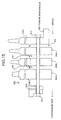
- Fig. 15 shows a rotor disk in a gas turbine conventionally used.
- a plurality of first stage rotor disks 500a to 500d are fastened by a spindle bolt 520 and nuts 510, to thereby constitute a rotor 600 of a gas turbine.
- Spaces between the rotor disks 550, 551 and 552 become a path for flowing steam supplied to the rotor blade (not shown), and cooling steam is supplied from a hollow turbine main spindle 560 side. This steam flows through the path formed by the spaces 550 and 551, and is supplied to the rotor blade from the space between the first stage rotor disk 500a and the second stage rotor disk 500b.
- the steam on the rotor disk side is higher than the air pressure on a compressor side
- the steam on the rotor disk 500a side leaks towards the compressor side, through a bolt hole provided in the first stage rotor disk 500a.
- the amount of leakage is not large as seen from the whole feed rate of the steam, but recently, it is tried to suppress the steam leakage, even in a small amount, and to use the cooling steam as effectively as possible. Therefore, it is necessary to reduce the steam leakage in this part as much as possible.
- a sealing structure of a spindle bolt according to the present invention is such that rotor disks and a connecting member on a compressor side are fixed by a spindle bolt, and between the first stage rotor disk and the connecting member on the compressor side, of a turbine rotor in a gas turbine having a steam path therein, the circumference of the spindle bolt is covered with a tubular member in which a section thereof vertical to the axial direction includes a section of a bolt hole for passing the spindle bolt therethrough, and the ends of the tubular member are made to abut on the first stage rotor disk and the connecting member on the compressor side, respectively.
- the tubular member covers the circumference of the spindle bolt to thereby seal the steam leaking through the bolt hole provided in the first stage rotor disk by this tubular member. Therefore, since the steam leakage can be reduced to effectively use the steam, the operation cost can be reduced.
- the cooling steam is generated by the exhaust gas of the gas turbine, and after cooling the rotor blade, drives an intermediate pressure turbine and the like. Since the consumption of steam in this part can be suppressed, the thermal efficiency is improved as a steam and gas turbine combined cycle power plant.
- the tubular member in this invention includes not only the one in which the cross section vertical to the axial direction is circular, but also tubular members in which the cross section is polygonal such as triangular and quadrangular.
- the tubular member may be formed integrally with the rotor disk and the connecting member on the compressor side.
- a sealing structure of the spindle bolt according to the next invention is such that rotor disks and a connecting member on a compressor side are fixed by a spindle bolt, and of a turbine rotor in a gas turbine having a steam path therein, a first annular member and a second annular member arranged inside the first annular member are arranged so that the ends thereof abut on the first stage rotor disks and the connecting member on the compressor side, and the spindle bolt is passed between the first annular member and the second annular member.
- annular member in this invention includes not only the one in which the cross section vertical to the axial direction is circular, but also annular members in which the cross section is polygonal such as triangular and quadrangular, and stelliform.
- the annular member may be formed integrally with the rotor disk and the connecting member on the compressor side.
- a sealing structure of the spindle bolt according to the next invention is such that, in the sealing structure of the spindle bolt, a sealant is provided at least on one side of between the end of the tubular member or the annular member and the first stage rotor disk, and between the end of the tubular member or the annular member and the connecting member on the compressor side.
- a metal or ceramics sealant is provided at the end of the tubular member or the annular member, to increase the steam sealing performance. Therefore, since the steam leakage can be further reduced, the steam can be used more effectively, and the thermal efficiency as the steam and gas turbine combined cycle power plant is also improved.
- a sealing structure of the spindle bolt according to the next invention is such that, in the sealing structure of the spindle bolt, a protrusion or a step that hinders the tubular member or the annular member from moving radially outwards of the rotor disk, is provided at least on one side of the first stage rotor disk and the connecting member on the compressor side.
- a step or the like is provided in the first stage rotor disk or the like, so as to prevent the tubular member or the annular member from moving radially outwards of the rotor disk due to a centrifugal force. Since the rotor disk of the gas turbine rotates at a high speed, the structural members in the rotating system are subjected to a large centrifugal force. When the tubular member or the annular member is eccentric due to the centrifugal force, the rotation balance is lost and spindle vibration increases, thereby a trip of the gas turbine may occur.
- a gas turbine according to the next invention is a gas turbine that has a plurality of rotor disks having a rotor blade in the periphery thereof, which cools the rotor blade or the rotor disk, and other hot members by steam.
- the gas turbine comprises a compressor that compresses air to produce combustion air, a combustor that supplies fuel to the combustion air produced by the compressor to generate combustion gas, and a turbine rotor having a feed path or a recovery path for the steam therein, in which rotor disks and a connecting member located on the compressor side are fixed by a spindle bolt, wherein between the first stage rotor disk and the connecting member, the circumference of the spindle bolt is covered with a tubular member in which a section thereof vertical to the axial direction includes a section of a bolt hole for passing the spindle bolt therethrough, and the opposite ends of the tubular member are made to abut on the first stage rotor disk and the connecting member on the compressor side, respectively.
- This gas turbine uses a turbine rotor having a sealing structure, in which a tubular member covers the circumference of the spindle bolt, and steam leaking from a bolt hole provided in the first stage rotor disk is sealed by the tubular member. Therefore, steam leakage at the spindle bolt portion can be reduced. As a result, in this gas turbine, wasteful use of the cooling steam can be suppressed. Further, in a steam and gas turbine combined cycle power plant using this gas turbine, thermal efficiency can be increased.
- a gas turbine according to the next invention is a gas turbine that has a plurality of rotor disks having a rotor blade in the periphery thereof, which cools the rotor blade or the rotor disk, and other hot members by steam.
- the gas turbine comprises a compressor that compresses air to produce combustion air, a combustor that supplies fuel to the combustion air produced by the compressor to generate combustion gas, and a turbine rotor having a feed path or a recovery path for the steam therein, in which rotor disks and a connecting member located on the compressor side are fixed by a spindle bolt, wherein a first annular member and a second annular member arranged inside the first annular member are arranged so that the ends thereof abut on the first stage rotor disks and the connecting member, and the spindle bolt is passed between the first annular member and the second annular member.
- annular members having a different outer dimension are arranged between the first stage rotor disk and the connecting member on the compressor side.
- the gas turbine uses a turbine rotor having a sealing structure, in which a spindle bolt is passed between these two annular members so as to prevent the steam leaking from a bolt hole, through which the spindle bolt passes. Therefore, steam leakage at the spindle bolt portion can be reduced. As a result, in this gas turbine, wasteful use of the cooling steam can be suppressed. Further, in a steam and gas turbine combined cycle power plant using this gas turbine, thermal efficiency can be increased.
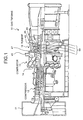
- Fig. 1 shows a gas turbine according to a first embodiment of the present invention
- Fig. 2 is a partial enlarged view that shows a sealing structure of a spindle bolt according to this gas turbine
- Fig. 3 shows a section of a tubular member and a section of a bolt hole
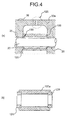
- Fig. 4 is a local sectional view that shows a sealing structure of a spindle bolt according to a first modified example in the first embodiment
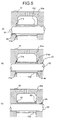
- Fig. 5 is a local sectional view that shows a sealing structure of a spindle bolt according to a second modified example in the first embodiment
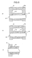
- Fig. 6 is a local sectional view that shows a sealing structure of a spindle bolt according to a third modified example in the first embodiment
- Fig. 1 shows a gas turbine according to a first embodiment of the present invention
- Fig. 2 is a partial enlarged view that shows a sealing structure of a spindle bolt according to this gas turbine
- Fig. 3 shows a section of a tubular member
- FIG. 7 is a local sectional view that shows a sealing structure of a spindle bolt according to a second embodiment
- Fig. 8 shows an example of an annular member
- Fig. 9 is a local sectional view that shows a first modified example in the second embodiment
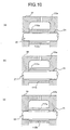
- Fig. 10 is a local sectional view that shows a sealing structure of a spindle bolt according to a second modified example of the second embodiment
- Fig. 11 is a local sectional view that shows a sealing structure of a spindle bolt according to a third embodiment of the present invention
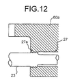
- Fig. 12 is a local sectional view that shows a sealing structure of a spindle bolt according to a modified example of the third embodiment
- FIG. 13 is a local sectional view that shows a sealing structure of a spindle bolt according to a fourth embodiment of the present invention
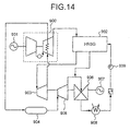
- Fig. 14 is a schematic diagram that shows a steam and gas turbine combined cycle power plant adopting steam cooling for cooling hot members
- Fig. 15 shows a rotor disk of a gas turbine conventionally used.
- FIG. 1 shows a gas turbine according to a first embodiment of the present invention.
- a gas turbine 10 is for cooling hot members of the gas turbine, such as a rotor blade, a rotor disk, or a stationary blade by steam.
- Air taken in from an air intake 11 is compressed by a compressor 12, to become high temperature and high pressure compressed air, and is fed to a combustor 13.
- the combustor 13 supplies gas fuel such as natural gas or the like, or liquid fuel such as gas oil, light fuel oil or the like to the compressed air, to burn the fuel, to thereby generate high temperature and high pressure combustion gas.
- This high temperature and high pressure combustion gas is guided to a combustor tail pipe 14, and injected to a turbine 15.
- the stationary blade and the rotor blade of the turbine 15 are cooled by steam, and this is supplied through a steam feed path (not shown) provided in a turbine main spindle 16.
- the steam supplied from the steam feed path changes the direction by 90 degrees in front of the rotor disk 50, is guided to a plurality of outer steam passes 60 provided in the circumferential direction of the rotor disk 50, and is then supplied to the rotor blade.
- the rotor disks 50 are fixed by a plurality of spindle bolts (not shown) axially penetrating the rotor disks 50, to thereby constitute a rotor of multiple stages.
- Fig. 2 is a partially enlarged view that shows a sealing structure of a spindle bolt according to this gas turbine.
- This structure has a feature in that the spindle bolt connecting the rotor disks is covered by a tubular member, so as to prevent the leakage of steam from the high pressure side, from a gap between the spindle bolt and a bolt hole.
- a first stage rotor disk 50a and a connecting member 30 on the compressor side are fastened by a spindle bolt 20 penetrating both the members.
- a tubular member 100 covers the spindle bolt 20.
- the length L1 of this tubular member 100 is set slightly larger than a gap L between the first stage rotor disk 50a and the connecting member 30 on the compressor side (see Fig. 2(b)).
- the tubular member shrinks, thereby becomes the same length as the gap L.
- the tubular member 100 shrinks by L1 - L, and the tubular member is pressed against the first stage rotor disk 50a and the connecting member 30 on the compressor side by the resilience of this shrunken portion. As a result, the steam sealing performance increases by this portion.
- Ends 100a and 100b of the tubular member 100 abut on the first stage rotor disk 50a and the connecting member 30 on the compressor side.
- the abutted portions of the tubular member 100 and the first stage rotor disk 50a and the like are machined smoothly, so that the steam passing through the space between the tubular member 100 and the first stage rotor disk 50a and the like is reduced as much as possible.
- the steam leaking from a bolt hole 25 on the first stage rotor disk 50a side and the spindle bolt 20 is confined within the tubular member 100, and hence steam leakage can be suppressed.
- the sealing structure of the spindle bolt since the amount of steam leaking from the first stage rotor disk 50a to the compressor side can be suppressed, the use efficiency of the steam can be increased.
- Figs. 3(a), (c) and (e) respectively show examples in which the external shape of the bolt hole 25 is included in the inner section of the tubular member 100 or the like.
- Figs. 3(b) and (d) show examples in which the external shape of the bolt hole 25 is included between the inner wall and the external wall of the tubular member 100 or the like. In either case, it corresponds to the relation of "a section of a tubular member vertical to the axial direction includes a section of a bolt hole" in the present invention.
- the cross section of the tubular member 100 is not limited to a circular shape, and as shown in Figs. 3(c) and (e), it includes polygonal shapes such as quadrangle and hexagon. Though not shown in these figures, an ellipse and one in which either the external shape or the inner diameter is circular and the other is polygonal are also included.
- Fig. 4 is a local sectional view that shows a sealing structure of a spindle bolt according to a first modified example in the first embodiment.
- the sealing structure of the spindle bolt has a feature in that a sealant is provided between the tubular member and the connecting member on the compressor side.
- a step 130 is provided, and a sealing member 120 is put in this step 130. Since the temperature of the first stage rotor disk 50a and the like rises during the operation of the gas turbine, heat resistance is required for the sealing member 120.
- This sealing member 120 should also have resilience, so as to absorb elongation of the tubular member 100, a curvic coupling 125 and the like.
- a metal seal or a ceramics seal may be used for this sealing member 120, in order to satisfy such requirement.
- the sealing member 120 is provided in the tubular member 100, but the sealing member 120 may be provided in the connecting member 30 on the compressor side or the first stage rotor disk 50a.
- this sealing member 120 may be provided only on the connecting member 30 on the compressor side, but in order to exhibit higher sealing performance, as shown in Fig. 4(b), it is desired to provide the sealing member 120 at the opposite ends of the tubular member 101 a.
- Fig. 5 is a local sectional view that shows a sealing structure of a spindle bolt according to a second modified example in the first embodiment.
- the sealing structure of the spindle bolt has a feature in that machining such as spot facing is provided to the connecting member on the compressor side or the first stage rotor disk, to form a step, and the end of the tubular member is fitted therein to thereby prevent the tubular member from moving radially outwards of the rotor disk.
- the bolt hole 25 for the spindle bolt 20 is provided in a connecting member 31 on the compressor side used for this sealing structure.
- the outlet of the bolt hole 25 is subjected to spot facing machining, to form a step 31 a. As shown in Fig.
- the end of the tubular member 102 is fitted in this step 31 a.
- a tubular member having a sealing member 120 (see Fig. 4) explained in the first modified example may be used.
- the sealing performance can be further increased, and hence the steam leakage can be further reduced.
- the tubular member 102 When the connecting member 31 on the compressor side rotates by the operation of the gas turbine, the tubular member 102 also rotates, and is subjected to a centrifugal force attributable to the rotation. Since the connecting member 31 on the compressor side and the first stage rotor disk 50a rotate at a speed as high as 3000 or 3600 rpm, the centrifugal force acting on the tubular member 102 becomes large. As a result, the tubular member 102 may move radially outward of the connecting member 31 on the compressor side, to thereby decrease the steam sealing performance.
- the step 31 a is provided only in the connecting member 31 on the compressor side, but as shown in Fig. 5(b), spot facing machining may be also applied to the bolt hole 25 in the first stage rotor disk 51 a, to provide a step 51 ax.
- spot facing machining may be also applied to the bolt hole 25 in the first stage rotor disk 51 a, to provide a step 51 ax.
- the movement of this member can be received by the opposite ends of the tubular member 102, and hence the movement of the tubular member 102 can be inhibited more stably.
- Fig. 5(c) shows another method for inhibiting the movement of the tubular member 102.
- a protrusion 80 is provided at the outlet of the bolt hole 25, to prevent the movement of the tubular member 102 by this protrusion 80.
- Fig. 6 is a local sectional view that shows a sealing structure of a spindle bolt according to a third modified example in the first embodiment.
- the sealing structure of the spindle bolt has a feature in that a tubular member covering the spindle bolt is integrally formed at least on one side of the connecting member on the compressor side and the first stage rotor disk.
- Fig. 6(a) shows an example in which a tubular member 103 is formed in a first stage rotor disk 52a.
- FIG. 6(b) shows an example in which tubular members 104 and 105 are respectively formed in a first stage rotor disk 53a and a connecting member 33 on the compressor side, and the ends of the tubular members 104 and 105 are made to abut on each other, to thereby seal the steam leakage from the bolt hole 25.
- the first stage rotor disk 52a and the tubular member 103 and the like are integrally formed, and hence a deviation of the tubular member 103 does not occur. Therefore, it is not necessary to provide deviation preventing means for the tubular member 103, and hence the structure becomes simple, and the reliability can be increased. Further, since it has an integral structure, the strength can be also increased, to thereby improve the durability.
- the sealing member may be provided on the sealing plane where the tubular member 103 or the like comes in contact with the connecting member 32 on the compressor side or the like. Such a structure helps to increase the steam sealing performance, reduce the steam leakage, and hence improve the thermal efficiency of the gas turbine.
- the configuration may be such that an external thread is provided in a tubular body 107, an internal thread engaging therewith is provided in a connecting member 34 on the compressor side, and the tubular body 107 is screwed therein to form a tubular member.
- Fig. 7 is a local sectional view that shows a sealing structure of a spindle bolt according to a second embodiment.
- this sealing structure two annular members having a different diameter are provided between the connecting member on the compressor side and the first stage rotor disk, and a spindle bolt is passed between these two annular members, to thereby fix the connecting member on the compressor side and the first stage rotor disk. It has a feature in that the steam leaking from the bolt hole provided in the first stage rotor disk is sealed by the two annular members.
- Two annular members 108 and 109 having a different diameter are provided between a connecting member 35 on the compressor side and a first stage rotor disk 54a.
- Spindle bolts 20 pass between the annular member 109 having a small diameter and the annular member 108 having a large diameter, to fasten the connecting member 35 on the compressor side and the first stage rotor disk 54a.
- a sealing member (not shown) may be provided at the ends of the annular members 108 and 109. Since the steam sealing performance can be increased by this sealing member, the waste of steam can be reduced than when the sealing member is not provided, and hence it is preferable. As the material of this sealing member, one explained in the first embodiment can be applied.
- the steam on the first stage rotor disk 54a tends to leak towards the compressor side, from the gap between the bolt hole 25 provided in the rotor disk and the spindle bolt 20.
- the steam stays in a space A (a portion surrounded by a dotted line in Fig. 7) formed between the annular members 108 and 109 having a different diameter, and does not leak outside of this space A, and hence the steam leaking from the first stage rotor disk 54a can be sealed.
- the waste of steam can be further reduced, and the thermal efficiency of the gas turbine can be further increased.
- Fig. 8 shows an example of an annular member.
- Fig. 8(a) shows octagonal annular members 108a and 109a
- Fig. 8(b) shows hexagonal annular members 108b and 109b.
- the annular members include not only the annular member in which a section thereof vertical to the axial direction is circular, but also annular members in which the section thereof vertical to the axial direction is polygonal such as octagonal or hexagonal.
- an annular member 108c in which the section thereof vertical to the axial direction is substantially stelliform is also included.
- the same type of shapes may be combined, such as a combination of a round shape and a round shape, or different shapes may be combined, such as a combination of a round shape and a polygon.
- Fig. 9 is a sectional view that shows a first modified example in the second embodiment.
- a step 55ax or the like may be provided in a first stage rotor disk 55a or the like, so that the step 55ax inhibits the annular members 108 and 109 from moving radially.
- a protrusion 81 may be provided instead of the step 55ax, to inhibit the radial movement of the annular members 108 and 109. In this manner, preventing the radial movement of the annular members 108 and the like, demonstrates stable sealing performance.
- this suppresses the change in rotation balance due to the movement of the annular member 108 and the like, and therefore avoids a trip of the gas turbine due to an increase of the spindle vibration.
- the gas turbine can be stably operated, while suppressing the steam leakage as much as possible.
- Fig. 10 is a local sectional view that shows a sealing structure of a spindle bolt according to a modified example of the second embodiment.
- the sealing structure of the spindle bolt according to this modified example has a feature in that the annular member is integrally formed at least on one side of the connecting member on the compressor side and the first stage rotor disk.
- Fig. 10(a) shows an example in which annular members 110a and 110b having a different diameter are formed in a first stage rotor disk 55a
- Fig. 10(a) shows an example in which an annular member 111 a, 111b is respectively formed in a first stage rotor disk 56a and a connecting member 38 on the compressor side.
- Fig. 10 shows an example in which annular member 111 a, 111b is respectively formed in a first stage rotor disk 56a and a connecting member 38 on the compressor side.
- FIG. 10(c) shows an example in which annular members 112a and 112b having a different diameter are formed respectively in a first stage rotor disk 57a and a connecting member 39 on the compressor side, and the ends thereof are made to abut on each other, to prevent the steam leakage from the bolt hole 25.
- the first stage rotor disk 55a and the annular member 110a and the like are integrally formed, and hence a deviation of the annular member 110a and the like do not occur. Therefore, it is not necessary to provide deviation preventing means for the annular member 110a and the like, and hence the structure becomes simple, and the reliability can be increased. Further, since it has an integral structure, the strength can be also increased, to thereby improve the durability.
- the sealing member explained in the first embodiment and the like may be provided on the sealing plane where the annular member 110a or the like comes in contact with the connecting member 37 on the compressor side or the like.
- Fig. 11 is a local sectional view that shows a sealing structure of a spindle bolt according to a third embodiment of the present invention.
- This sealing structure has a feature in that the bolt hole provided in the first stage rotor disk is adhered to the spindle bolt, to thereby seal the steam leaking from the through hole.
- a bolt hole 26 for passing a spindle bolt 21 therethrough is provided in a first stage rotor disk 58a, and a taper 26a is formed at the opening of the bolt hole 26.
- the spindle bolt 21 comprises a large diameter portion 21a and a small diameter portion 21 b, and a taper 21c similar to the taper 26a is formed between the large diameter portion 21 a and the small diameter portion 21 b.
- a bolt hole 70 larger than the large diameter portion 21 a is formed in a connecting member 40 on the compressor side, so that the large diameter portion 21 a of the spindle bolt 21 can pass therethrough.
- the spindle bolt 21 is inserted into the bolt hole 26 provided in the first stage rotor disk 58a, so that the taper 21c of the spindle bolt 21 comes in contact with the taper 26a of the bolt hole 26.
- the spindle bolt 21 passes through from a second stage rotor disk to a third stage rotor disk.
- the first stage to the third stage rotor disks are fixed by fastening a nut from outside of the third stage rotor disk.
- the taper 21 c of the spindle bolt 21 is allowed to adhere more firmly to the taper 26a of the bolt hole 26 provided in the first stage rotor disk 58a, by fastening the nut.
- the steam on the first stage rotor disk 58a side tends to leak towards the compressor side through a gap between the bolt hole 26 and the spindle bolt 21.
- the sealing structure since the taper 26a of the bolt hole 26 and the taper 21 c of the spindle bolt 21 adhere to each other, the leakage of the steam in this part can be prevented.
- a sealing member is provided between the spindle bolt 21 and the bolt hole 26, the sealability can be further increased, which is preferable.
- a step 59ax may be provided in a first stage rotor disk 59a, so as to abut on a step provided in a spindle bolt 22, to thereby seal the steam, without using the taper.
- a sealing member 90 may be arranged between the spindle bolt 21 and the bolt hole 26, so that the internal surface of the bolt hole 26 and the outer circumference of the spindle bolt 21 come in line contact with this sealing member, to thereby seal the steam.
- the steam sealing performance can be increased than by a surface contact, and machining becomes easy, which is preferable.
- this sealing structure since neither a tubular member nor an annular member as in the above sealing structures is required, steam leakage can be prevented with a small number of parts. Further, since the tubular member or the like is not used, the rotation balance is hardly lost, and a trip of the gas turbine due to the spindle vibration hardly occurs, thereby enabling stable operation.
- Fig. 12 is a local sectional view that shows a sealing structure of a spindle bolt according to a modified example of the third embodiment.
- This sealing structure has a feature in that in the sealing structure, an internal thread is provided at an opening 27a of a bolt hole 27 provided in a first stage rotor disk 60a, an external thread engaging with the internal thread is provided on a spindle bolt 23, and the both screws are fastened at the opening 27a of the bolt hole 27 to seal the steam.
- the steam on the first stage rotor disk 60a side leaks through a gap between the bolt hole 27 and the spindle bolt 23.
- the steam is sealed in this part.
- the sealing performance becomes considerably high, as compared with the sealing means such as the surface contact or the line contact described above. Therefore, steam leakage can be prevented substantially completely, and hence the steam can be used for cooling the rotor blade without being wasted.
- the adhesion between the spindle bolt 21 and the like and the bolt hole 26 and the like becomes weak due to the thermal expansion of the spindle bolt (see Fig.
- Fig. 13 is a local sectional view that shows a sealing structure of a spindle bolt according to a fourth embodiment of the present invention.
- This sealing structure has a feature in that an elastic member that can deform in the radial direction of the spindle bolt is provided between a spindle bolt and a through hole provided in a first stage rotor disk, to thereby prevent steam leakage.
- a spherical elastic strengthening member 94 is provided on the side of a spindle bolt 29a according to the fourth embodiment.
- the internal surface of a bolt hole 28 provided in a first stage rotor disk 61a comes in contact with the spherical elastic strengthening member 94, to thereby seal the steam.
- This spherical elastic strengthening member 94 is made of a metal material, since a heat resistance and elasticity are required in the spherical elastic strengthening member 94, and for example, it is manufactured from a nickel base alloy or the like.
- the elastic strengthening member 94 is fitted to a spindle bolt 29a by welding or the like.
- the elastic strengthening member 94 may be provided on the bolt hole 28 side. In this case, as shown in Fig. 13(b), if the structure is such that a tube 95 fitted with an elastic strengthening member 96 is inserted into the bolt hole 28, and a spindle bolt 29b is inserted into this tube 95, repair and replacement become easy, when the elastic strengthening member 96 is damaged, which is preferable.
- Fig. 13(a) will be referenced next for explanation.
- the side of the elastic strengthening member 94 comes in contact with the internal surface of the bolt hole 28. Since the elastic strengthening member 94 can deform radially, even if the spindle bolt 29a moves radially, the elastic strengthening member 94 can absorb the movement and maintain the steam sealing performance.
- the steam leaking through a gap between the spindle bolt 29a and the bolt hole 28 is sealed by the elastic strengthening member 94, and hence steam hardly leaks towards the compressor.
- This sealing structure does not use a tubular member or the like as in the sealing structure according to the first embodiment and the like, and hence the rotation balance is hardly lost. As a result, the steam leakage can be reduced as much as possible, while keeping a trip of the gas turbine to a minimum.
- a protrusion 97 may be provided on the side of the spindle bolt 29c and inside the elastic strengthening member 94, to restrict the radial deformation of the elastic strengthening member 94. It is preferable, because a damage resulting from an increase of the deformation of the elastic strengthening member 94 can be suppressed by this protrusion.
- a hard coating may be applied on the internal surface of the bolt hole 28, so as to protect the internal surface of the bolt hole 28 from fretting wear due to the contact with the elastic strengthening member 94. By applying the hard coating, the wear on the internal surface of the bolt hole 28 hardly occurs, thereby the durability increases, and time and energy are not required for the maintenance, which is preferable.
- a TiC or TiN layer may be physically formed by physical vapor deposition (PVD), other than chromium plating.
- PVD physical vapor deposition
- high-carbon high chrome steel, high manganese steel, a Co-Cr-W alloy (Stellite) or the like may be welded by a hard facing processing.
- Fig. 14 is a schematic diagram that shows a stem and gas turbine combined cycle power plant adopting steam cooling for cooling the hot members.
- thermal energy contained in the exhaust gas of the gas turbine is recovered by a heat recovery steam generator (HRSG).
- HRSG heat recovery steam generator
- Steam is generated by the thermal energy in the recovered exhaust gas of the gas turbine, to drive a steam turbine by the high temperature and high pressure steam, to thereby generate power by a generator connected thereto.
- HRSG heat recovery steam generator
- this gas turbine 900 uses steam for cooling hot members, such as rotor and stationary blades and rotor disks.
- a turbine in which any one of the sealing structures of the spindle bolt explained in the first to the fourth embodiments is used in this gas turbine 900.
- the gas turbine 900 is connected to a first generator 901, and the gas turbine 900 drives the first generator 901 to generate power.
- the exhaust gas of the gas turbine 900 has a temperature of about several hundred degrees, and hence this exhaust gas is guided to the HRSG 902, to generate steam.
- the steam generated in the HRSG 902 is first guided to a high pressure steam turbine 903, to drive this.
- the exhaust steam of the high pressure steam turbine 903 is guided to the gas turbine 900, and used for cooling hot members, such as the rotor blade and the stationary blade.
- the steam having cooled the hot members in the gas turbine 900 is guided to a mixing chamber 904 and supplied to an intermediate pressure steam turbine 905.
- the steam having driven the intermediate pressure steam turbine 905 is supplied to a low pressure steam turbine 906 to drive this.
- the high pressure steam turbine 903, the intermediate pressure steam turbine 905, and the low pressure steam turbine 906 are serially connected, to rotate a second generator 907 connected with the output shafts thereof, to thereby generate power.
- the steam having driven the intermediate pressure steam turbine 905 and the low pressure steam turbine 906 is recovered to a water form by a steam condenser 908, and then supplied again to the HRSG 902 by a pump 909.
- the water is turned into steam again by an evaporator (not shown) provided in the HRSG 902, superheated by a superheater (not, shown), and then supplied to the high pressure steam turbine 903 to repeat the process.
- the gas turbine 900 to which any one of the sealing structures of the spindle bolt explained in the first to the fourth embodiments is applied, is used. Therefore, since the amount of steam leaking through a gap between the spindle bolt and the bolt hole can be reduced, precious steam can be effectively used, thereby suppressing a loss to a minimum. As a result, the thermal efficiency of the steam and gas turbine combined cycle power plant can be improved.
- the circumference of the spindle bolt is covered with a tubular member, so that the steam leaking through the bolt hole provided in the first stage rotor disk is sealed by this tubular member. Therefore, the steam leakage is reduced, and the steam can be effectively used, and hence the operation cost can be reduced. Further, the cooling steam is generated from exhaust gas of the gas turbine, and after having cooled the rotor blade, the steam drives the intermediate pressure steam turbine and the like. The steam leakage in this part can be reduced, and a decrease in the output of the steam turbine can be suppressed. As a result, the thermal efficiency as the steam and gas turbine combined cycle power plant is improved.
- a metal or ceramics sealant is provided at the end of the tubular member or the annular member, to increase the steam sealing performance. Therefore, since the steam leakage can be further reduced, the steam can be used more effectively, and hence the thermal efficiency as the steam and gas turbine combined cycle power plant is improved.
- a step or the like is provided in the first stage rotor disk or the like, to prevent the tubular member or the annular member from moving radially outwards of the rotor disk due to the centrifugal force. Since the rotor disk of the gas turbine rotates at a high speed, the structural members in the rotating system are subjected to a large centrifugal force. When the tubular member or the annular member is eccentric due to the centrifugal force, the rotation balance is lost and spindle vibration increases, thereby a trip of the gas turbine may occur.
- the circumference of the spindle bolt is covered with a tubular member, and the steam leaking through the bolt hole provided in the first stage rotor disk is sealed by this tubular member.
- the steam leakage in the spindle bolt can be reduced, and hence in this gas turbine, wastefulness of the cooling steam can be suppressed.
- the thermal efficiency can be increased.
- two annular members having a different outer dimension are arranged between the first stage rotor disk and the connecting member on the compressor side, and the spindle bolt is passed between these two annular members, to prevent the steam leaking from a bolt hole, through which the spindle bolt passes. Therefore, steam leakage in the spindle bolt can be reduced to suppress wastefulness of the cooling steam. Further, in a steam and gas turbine combined cycle power plant using this gas turbine, the thermal efficiency can be increased.
- the sealing structure of the spindle bolt and the gas turbine according to the present invention are useful for a gas turbine that uses steam as a cooling medium for hot members such as a rotor blade and a rotor disk, and are suitable for increasing the efficiency, by reducing leakage of the steam and increasing the use efficiency of the steam.
Landscapes
- Engineering & Computer Science (AREA)
- Mechanical Engineering (AREA)
- General Engineering & Computer Science (AREA)
- Chemical & Material Sciences (AREA)
- Combustion & Propulsion (AREA)
- Turbine Rotor Nozzle Sealing (AREA)
Abstract
A first stage rotor disk (50a) and a connecting member (30) on the compressor side are fixed by a spindle bolt (20). The spindle bolt (20) is covered with a tubular member (100), between the first stage rotor disk (50a) and the connecting member (30) on the compressor side. <IMAGE>
Description
The present invention relates to a gas turbine that uses steam
as a cooling medium for hot members. More particularly, the present
invention relates to a gas turbine in which steam leakage is decreased
to increase the use efficiency of the steam, to thereby enable efficient
operation, and a sealing structure for a spindle bolt connecting rotor
disks.
A technique for cooling hot members, such as a rotor blade, a
rotor disk, or a stationary blade in a gas turbine, by using steam instead
of air as a cooling medium, is now being used, in order to increase the
thermal efficiency in the gas turbine. This is due to the following
reasons. The specific heat at constant pressure of dry steam is cp =
1.86 kJ/kgK under a normal condition, which is a value almost twice as
large as the specific heat at constant pressure of air, cp = 1.00 kJ/kgK.
Therefore, steam has a large heat capacity and a high endothermic
effect, as compared with air of the same mass. Further, when wet
steam is used as the cooling medium, the endothermic effect can be
fu rther increased, since the latent heat of vaporization for the wet
amount can be also used for cooling. Hence, the cooling efficiency
can be increased than when using air, and the turbine inlet temperature
of the combustion gas can be increased, thereby enabling an
improvement in the thermal efficiency.
In the conventional air cooling, air from a compressor is used as
a cooling medium for rotor and stationary blades of the turbine.
However, when this compressed air is used for cooling, the work that
can be taken out from the turbine decreases. If steam is used instead
of air, the cooling air for the rotor and stationary blades can be saved,
and hence the work that can be recovered by the turbine increases by
this amount, thereby the work that can be taken out from the turbine
can be increased.
Fig. 15 shows a rotor disk in a gas turbine conventionally used.
A plurality of first stage rotor disks 500a to 500d are fastened by a
spindle bolt 520 and nuts 510, to thereby constitute a rotor 600 of a gas
turbine. Spaces between the rotor disks 550, 551 and 552 become a
path for flowing steam supplied to the rotor blade (not shown), and
cooling steam is supplied from a hollow turbine main spindle 560 side.
This steam flows through the path formed by the spaces 550 and 551,
and is supplied to the rotor blade from the space between the first stage
rotor disk 500a and the second stage rotor disk 500b.
However, since the steam pressure on the rotor disk side is
higher than the air pressure on a compressor side, the steam on the
rotor disk 500a side leaks towards the compressor side, through a bolt
hole provided in the first stage rotor disk 500a. The amount of leakage
is not large as seen from the whole feed rate of the steam, but recently,
it is tried to suppress the steam leakage, even in a small amount, and
to use the cooling steam as effectively as possible. Therefore, it is
necessary to reduce the steam leakage in this part as much as
possible.
It is therefore an object of the present invention to provide a gas
turbine that can reduce the leakage of steam to be used for cooling the
rotor blade and the like and increase the use efficiency of the steam,
thereby enabling efficient operation, and a sealing structure of the
spindle bolt for connecting the rotor disks.
A sealing structure of a spindle bolt according to the present
invention is such that rotor disks and a connecting member on a
compressor side are fixed by a spindle bolt, and between the first stage
rotor disk and the connecting member on the compressor side, of a
turbine rotor in a gas turbine having a steam path therein, the
circumference of the spindle bolt is covered with a tubular member in
which a section thereof vertical to the axial direction includes a section
of a bolt hole for passing the spindle bolt therethrough, and the ends of
the tubular member are made to abut on the first stage rotor disk and
the connecting member on the compressor side, respectively.
In this sealing structure of this spindle bolt, the tubular member
covers the circumference of the spindle bolt to thereby seal the steam
leaking through the bolt hole provided in the first stage rotor disk by this
tubular member. Therefore, since the steam leakage can be reduced
to effectively use the steam, the operation cost can be reduced. The
cooling steam is generated by the exhaust gas of the gas turbine, and
after cooling the rotor blade, drives an intermediate pressure turbine
and the like. Since the consumption of steam in this part can be
suppressed, the thermal efficiency is improved as a steam and gas
turbine combined cycle power plant. The tubular member in this
invention includes not only the one in which the cross section vertical to
the axial direction is circular, but also tubular members in which the
cross section is polygonal such as triangular and quadrangular. The
tubular member may be formed integrally with the rotor disk and the
connecting member on the compressor side.
A sealing structure of the spindle bolt according to the next
invention is such that rotor disks and a connecting member on a
compressor side are fixed by a spindle bolt, and of a turbine rotor in a
gas turbine having a steam path therein, a first annular member and a
second annular member arranged inside the first annular member are
arranged so that the ends thereof abut on the first stage rotor disks and
the connecting member on the compressor side, and the spindle bolt is
passed between the first annular member and the second annular
member.
In this sealing structure of the spindle bolt, two annular
members having a different outer dimension are arranged between the
first stage rotor disk and the connecting member on the compressor
side, and the spindle bolt is passed between these two annular
members, to prevent the steam leaking from a bolt hole, through which
the spindle bolt passes. Since steam leakage is reduced, and steam
can be used effectively, the operation cost can be reduced. Since the
consumption of steam in this part can be reduced, the thermal
efficiency is improved as a steam and gas turbine combined cycle
power plant. The annular member in this invention includes not only
the one in which the cross section vertical to the axial direction is
circular, but also annular members in which the cross section is
polygonal such as triangular and quadrangular, and stelliform. The
annular member may be formed integrally with the rotor disk and the
connecting member on the compressor side.
A sealing structure of the spindle bolt according to the next
invention is such that, in the sealing structure of the spindle bolt, a
sealant is provided at least on one side of between the end of the
tubular member or the annular member and the first stage rotor disk,
and between the end of the tubular member or the annular member and
the connecting member on the compressor side. In the sealing
structure of the spindle bolt, a metal or ceramics sealant is provided at
the end of the tubular member or the annular member, to increase the
steam sealing performance. Therefore, since the steam leakage can
be further reduced, the steam can be used more effectively, and the
thermal efficiency as the steam and gas turbine combined cycle power
plant is also improved.
A sealing structure of the spindle bolt according to the next
invention is such that, in the sealing structure of the spindle bolt, a
protrusion or a step that hinders the tubular member or the annular
member from moving radially outwards of the rotor disk, is provided at
least on one side of the first stage rotor disk and the connecting
member on the compressor side.
In the sealing structure of the spindle bolt, a step or the like is
provided in the first stage rotor disk or the like, so as to prevent the
tubular member or the annular member from moving radially outwards
of the rotor disk due to a centrifugal force. Since the rotor disk of the
gas turbine rotates at a high speed, the structural members in the
rotating system are subjected to a large centrifugal force. When the
tubular member or the annular member is eccentric due to the
centrifugal force, the rotation balance is lost and spindle vibration
increases, thereby a trip of the gas turbine may occur. In this sealing
structure, since the movement of the tubular member or the like is
hindered by making the step or the like abut on the tubular member, a
deviation of the tubular member or the like can be suppressed. As a
result, since the gas turbine can be operated without losing the rotation
balance, and hence a trip of the gas turbine can be suppressed.
A gas turbine according to the next invention is a gas turbine
that has a plurality of rotor disks having a rotor blade in the periphery
thereof, which cools the rotor blade or the rotor disk, and other hot
members by steam. The gas turbine comprises a compressor that
compresses air to produce combustion air, a combustor that supplies
fuel to the combustion air produced by the compressor to generate
combustion gas, and a turbine rotor having a feed path or a recovery
path for the steam therein, in which rotor disks and a connecting
member located on the compressor side are fixed by a spindle bolt,
wherein between the first stage rotor disk and the connecting member,
the circumference of the spindle bolt is covered with a tubular member
in which a section thereof vertical to the axial direction includes a
section of a bolt hole for passing the spindle bolt therethrough, and the
opposite ends of the tubular member are made to abut on the first stage
rotor disk and the connecting member on the compressor side,
respectively.
This gas turbine uses a turbine rotor having a sealing structure,
in which a tubular member covers the circumference of the spindle bolt,
and steam leaking from a bolt hole provided in the first stage rotor disk
is sealed by the tubular member. Therefore, steam leakage at the
spindle bolt portion can be reduced. As a result, in this gas turbine,
wasteful use of the cooling steam can be suppressed. Further, in a
steam and gas turbine combined cycle power plant using this gas
turbine, thermal efficiency can be increased.
A gas turbine according to the next invention is a gas turbine
that has a plurality of rotor disks having a rotor blade in the periphery
thereof, which cools the rotor blade or the rotor disk, and other hot
members by steam. The gas turbine comprises a compressor that
compresses air to produce combustion air, a combustor that supplies
fuel to the combustion air produced by the compressor to generate
combustion gas, and a turbine rotor having a feed path or a recovery
path for the steam therein, in which rotor disks and a connecting
member located on the compressor side are fixed by a spindle bolt,
wherein a first annular member and a second annular member arranged
inside the first annular member are arranged so that the ends thereof
abut on the first stage rotor disks and the connecting member, and the
spindle bolt is passed between the first annular member and the second
annular member.
In this gas turbine, two annular members having a different
outer dimension are arranged between the first stage rotor disk and the
connecting member on the compressor side. The gas turbine uses a
turbine rotor having a sealing structure, in which a spindle bolt is
passed between these two annular members so as to prevent the steam
leaking from a bolt hole, through which the spindle bolt passes.
Therefore, steam leakage at the spindle bolt portion can be reduced.
As a result, in this gas turbine, wasteful use of the cooling steam can be
suppressed. Further, in a steam and gas turbine combined cycle
power plant using this gas turbine, thermal efficiency can be increased.
Fig. 1 shows a gas turbine according to a first embodiment of
the present invention; Fig. 2 is a partial enlarged view that shows a
sealing structure of a spindle bolt according to this gas turbine; Fig. 3
shows a section of a tubular member and a section of a bolt hole; Fig. 4
is a local sectional view that shows a sealing structure of a spindle bolt
according to a first modified example in the first embodiment; Fig. 5 is a
local sectional view that shows a sealing structure of a spindle bolt
according to a second modified example in the first embodiment; Fig. 6
is a local sectional view that shows a sealing structure of a spindle bolt
according to a third modified example in the first embodiment; Fig. 7 is
a local sectional view that shows a sealing structure of a spindle bolt
according to a second embodiment; Fig. 8 shows an example of an
annular member; Fig. 9 is a local sectional view that shows a first
modified example in the second embodiment; Fig. 10 is a local sectional
view that shows a sealing structure of a spindle bolt according to a
second modified example of the second embodiment; Fig. 11 is a local
sectional view that shows a sealing structure of a spindle bolt according
to a third embodiment of the present invention; Fig. 12 is a local
sectional view that shows a sealing structure of a spindle bolt according
to a modified example of the third embodiment; Fig. 13 is a local
sectional view that shows a sealing structure of a spindle bolt according
to a fourth embodiment of the present invention; Fig. 14 is a schematic
diagram that shows a steam and gas turbine combined cycle power
plant adopting steam cooling for cooling hot members; and Fig. 15
shows a rotor disk of a gas turbine conventionally used.
The present invention will be explained in detail, with reference
to the drawings, but the present invention is not limited by the
embodiments. The components in the embodiments include ones that
can be assumed easily by those skilled in the art.
Fig. 1 shows a gas turbine according to a first embodiment of
the present invention. A gas turbine 10 is for cooling hot members of
the gas turbine, such as a rotor blade, a rotor disk, or a stationary blade
by steam. Air taken in from an air intake 11 is compressed by a
compressor 12, to become high temperature and high pressure
compressed air, and is fed to a combustor 13. The combustor 13
supplies gas fuel such as natural gas or the like, or liquid fuel such as
gas oil, light fuel oil or the like to the compressed air, to burn the fuel, to
thereby generate high temperature and high pressure combustion gas.
This high temperature and high pressure combustion gas is guided to a
combustor tail pipe 14, and injected to a turbine 15.
The stationary blade and the rotor blade of the turbine 15 are
cooled by steam, and this is supplied through a steam feed path (not
shown) provided in a turbine main spindle 16. The steam supplied
from the steam feed path changes the direction by 90 degrees in front
of the rotor disk 50, is guided to a plurality of outer steam passes 60
provided in the circumferential direction of the rotor disk 50, and is then
supplied to the rotor blade. The rotor disks 50 are fixed by a plurality
of spindle bolts (not shown) axially penetrating the rotor disks 50, to
thereby constitute a rotor of multiple stages.
Fig. 2 is a partially enlarged view that shows a sealing structure
of a spindle bolt according to this gas turbine. This structure has a
feature in that the spindle bolt connecting the rotor disks is covered by
a tubular member, so as to prevent the leakage of steam from the high
pressure side, from a gap between the spindle bolt and a bolt hole. As
shown in Fig. 2, a first stage rotor disk 50a and a connecting member
30 on the compressor side are fastened by a spindle bolt 20 penetrating
both the members. Between the first stage rotor disk 50a and the
connecting member 30 on the compressor side, a tubular member 100
covers the spindle bolt 20.
The length L1 of this tubular member 100 is set slightly larger
than a gap L between the first stage rotor disk 50a and the connecting
member 30 on the compressor side (see Fig. 2(b)). When the first
stage rotor disk 50a and the connecting member 30 on the compressor
side are fastened by the spindle bolt 20, the tubular member shrinks,
thereby becomes the same length as the gap L. The tubular member
100 shrinks by L1 - L, and the tubular member is pressed against the
first stage rotor disk 50a and the connecting member 30 on the
compressor side by the resilience of this shrunken portion. As a result,
the steam sealing performance increases by this portion.
The relation between the section of the tubular member 100 and
the section of the bolt hole 25 is explained in Fig. 3. Figs. 3(a), (c) and
(e) respectively show examples in which the external shape of the bolt
hole 25 is included in the inner section of the tubular member 100 or
the like. Figs. 3(b) and (d) show examples in which the external shape
of the bolt hole 25 is included between the inner wall and the external
wall of the tubular member 100 or the like. In either case, it
corresponds to the relation of "a section of a tubular member vertical to
the axial direction includes a section of a bolt hole" in the present
invention. As is clearly seen from these figures, the cross section of
the tubular member 100 is not limited to a circular shape, and as shown
in Figs. 3(c) and (e), it includes polygonal shapes such as quadrangle
and hexagon. Though not shown in these figures, an ellipse and one
in which either the external shape or the inner diameter is circular and
the other is polygonal are also included.
Fig. 4 is a local sectional view that shows a sealing structure of
a spindle bolt according to a first modified example in the first
embodiment. The sealing structure of the spindle bolt has a feature in
that a sealant is provided between the tubular member and the
connecting member on the compressor side. At the end of the tubular
member 100 used in this sealing structure, a step 130 is provided, and
a sealing member 120 is put in this step 130. Since the temperature of
the first stage rotor disk 50a and the like rises during the operation of
the gas turbine, heat resistance is required for the sealing member 120.
This sealing member 120 should also have resilience, so as to absorb
elongation of the tubular member 100, a curvic coupling 125 and the
like. A metal seal or a ceramics seal may be used for this sealing
member 120, in order to satisfy such requirement.
In this example, the sealing member 120 is provided in the
tubular member 100, but the sealing member 120 may be provided in
the connecting member 30 on the compressor side or the first stage
rotor disk 50a. In that case, if a spot facing is provided in the bolt hole
25, through which the spindle bolt passes, in the connecting member 30
on the compressor side or the like, and the sealing member 120 is fitted
therein, stable sealing performance can be demonstrated, while
suppressing a deviation of the sealing member. Therefore, it is
preferable. As shown in Fig. 4(a), this sealing member 120 may be
provided only on the connecting member 30 on the compressor side,
but in order to exhibit higher sealing performance, as shown in Fig. 4(b),
it is desired to provide the sealing member 120 at the opposite ends of
the tubular member 101 a.
When the first stage rotor disk 50a and the connecting member
30 on the compressor side are combined, after the spindle bolt 20 is
inserted in the tubular member 100, nuts 24 (see Fig. 2) are fastened to
assemble. When the nuts 24 are fastened, the sealing member 120
provided in the tubular member 100 shrinks axially due to the clamping
force of the nuts 24, and hence the steam leaking from the bolt hole 25
in the first stage rotor disk 50a can be sealed.
Fig. 5 is a local sectional view that shows a sealing structure of
a spindle bolt according to a second modified example in the first
embodiment. The sealing structure of the spindle bolt has a feature in
that machining such as spot facing is provided to the connecting
member on the compressor side or the first stage rotor disk, to form a
step, and the end of the tubular member is fitted therein to thereby
prevent the tubular member from moving radially outwards of the rotor
disk. The bolt hole 25 for the spindle bolt 20 is provided in a
connecting member 31 on the compressor side used for this sealing
structure. The outlet of the bolt hole 25 is subjected to spot facing
machining, to form a step 31 a. As shown in Fig. 5(a), the end of the
tubular member 102 is fitted in this step 31 a. For this tubular member
102, a tubular member having a sealing member 120 (see Fig. 4)
explained in the first modified example may be used. By using this,
the sealing performance can be further increased, and hence the steam
leakage can be further reduced.
When the connecting member 31 on the compressor side rotates
by the operation of the gas turbine, the tubular member 102 also rotates,
and is subjected to a centrifugal force attributable to the rotation.
Since the connecting member 31 on the compressor side and the first
stage rotor disk 50a rotate at a speed as high as 3000 or 3600 rpm, the
centrifugal force acting on the tubular member 102 becomes large. As
a result, the tubular member 102 may move radially outward of the
connecting member 31 on the compressor side, to thereby decrease the
steam sealing performance. In the sealing structure of the spindle bolt
according to this modified example, since the movement of the tubular
member 102 can be hindered by the step 31 a provided in the
connecting member 31 on the compressor side, the steam sealing
performance can be ensured even during the operation of the gas
turbine. As a result, stable steam sealing performance can be
exhibited, regardless of the operation condition of the gas turbine, to
thereby minimize the steam leakage.
When the tubular member 102 moves in the radial direction of
the first stage rotor disk 50a, the balance of the rotating system is lost,
and the spindle vibration may exceed a tolerance. Thereby, a trip
(suspension) of the gas turbine may occur. However, by this modified
example, such radial movement of the tubular member 102 can be
hindered, and hence the balance of the rotating system is hardly
affected. Therefore, even if the tubular member 102 is provided, the
spindle vibration can be suppressed within the tolerance, and hence a
trip of the gas turbine can be avoided.
In the example, the step 31 a is provided only in the connecting
member 31 on the compressor side, but as shown in Fig. 5(b), spot
facing machining may be also applied to the bolt hole 25 in the first
stage rotor disk 51 a, to provide a step 51 ax. By providing the step
51 ax, the movement of this member can be received by the opposite
ends of the tubular member 102, and hence the movement of the
tubular member 102 can be inhibited more stably. Fig. 5(c) shows
another method for inhibiting the movement of the tubular member 102.
As shown in this figure, a protrusion 80 is provided at the outlet of the
bolt hole 25, to prevent the movement of the tubular member 102 by
this protrusion 80.
Fig. 6 is a local sectional view that shows a sealing structure of
a spindle bolt according to a third modified example in the first
embodiment. The sealing structure of the spindle bolt has a feature in
that a tubular member covering the spindle bolt is integrally formed at
least on one side of the connecting member on the compressor side
and the first stage rotor disk. Fig. 6(a) shows an example in which a
tubular member 103 is formed in a first stage rotor disk 52a. Fig. 6(b)
shows an example in which tubular members 104 and 105 are
respectively formed in a first stage rotor disk 53a and a connecting
member 33 on the compressor side, and the ends of the tubular
members 104 and 105 are made to abut on each other, to thereby seal
the steam leakage from the bolt hole 25.
In this sealing structure according to this modified example, in
addition to the action and effect exhibited by the sealing structure
according to the first embodiment, the first stage rotor disk 52a and the
tubular member 103 and the like are integrally formed, and hence a
deviation of the tubular member 103 does not occur. Therefore, it is
not necessary to provide deviation preventing means for the tubular
member 103, and hence the structure becomes simple, and the
reliability can be increased. Further, since it has an integral structure,
the strength can be also increased, to thereby improve the durability.
The sealing member may be provided on the sealing plane where the
tubular member 103 or the like comes in contact with the connecting
member 32 on the compressor side or the like. Such a structure helps
to increase the steam sealing performance, reduce the steam leakage,
and hence improve the thermal efficiency of the gas turbine. As shown
in Fig. 6(c), the configuration may be such that an external thread is
provided in a tubular body 107, an internal thread engaging therewith is
provided in a connecting member 34 on the compressor side, and the
tubular body 107 is screwed therein to form a tubular member. By
having such a configuration, machining becomes easy, and even when
the tubular body 107 is broken, replacement becomes easy.
Fig. 7 is a local sectional view that shows a sealing structure of
a spindle bolt according to a second embodiment. In this sealing
structure, two annular members having a different diameter are
provided between the connecting member on the compressor side and
the first stage rotor disk, and a spindle bolt is passed between these
two annular members, to thereby fix the connecting member on the
compressor side and the first stage rotor disk. It has a feature in that
the steam leaking from the bolt hole provided in the first stage rotor disk
is sealed by the two annular members.
Two annular members 108 and 109 having a different diameter
are provided between a connecting member 35 on the compressor side
and a first stage rotor disk 54a. Spindle bolts 20 pass between the
annular member 109 having a small diameter and the annular member
108 having a large diameter, to fasten the connecting member 35 on the
compressor side and the first stage rotor disk 54a. As shown in Fig.
7(c), the length L2 of the annular members 108 and 109 is slightly
larger than a gap L between the connecting member 35 on the
compressor side and the first stage rotor disk 54a, and the annular
members shrink by a shrinkage allowance Δ = L2 - L, by fastening the
spindle bolts 20. Since the working face can be compressed by this
shrinkage allowance Δ, stable sealing performance can be exhibited,
regardless of the operation condition of the gas turbine.
As explained in the first embodiment, a sealing member (not
shown) may be provided at the ends of the annular members 108 and
109. Since the steam sealing performance can be increased by this
sealing member, the waste of steam can be reduced than when the
sealing member is not provided, and hence it is preferable. As the
material of this sealing member, one explained in the first embodiment
can be applied.
The steam on the first stage rotor disk 54a tends to leak towards
the compressor side, from the gap between the bolt hole 25 provided in
the rotor disk and the spindle bolt 20. However, the steam stays in a
space A (a portion surrounded by a dotted line in Fig. 7) formed
between the annular members 108 and 109 having a different diameter,
and does not leak outside of this space A, and hence the steam leaking
from the first stage rotor disk 54a can be sealed. As a result, the
waste of steam can be further reduced, and the thermal efficiency of the
gas turbine can be further increased.
Fig. 8 shows an example of an annular member. Fig. 8(a)
shows octagonal annular members 108a and 109a, and Fig. 8(b) shows
hexagonal annular members 108b and 109b. The annular members
include not only the annular member in which a section thereof vertical
to the axial direction is circular, but also annular members in which the
section thereof vertical to the axial direction is polygonal such as
octagonal or hexagonal. As shown in Fig. 8(c), an annular member
108c in which the section thereof vertical to the axial direction is
substantially stelliform is also included. As a combination of the
annular members, the same type of shapes may be combined, such as
a combination of a round shape and a round shape, or different shapes
may be combined, such as a combination of a round shape and a
polygon.
Fig. 9 is a sectional view that shows a first modified example in
the second embodiment. As shown in Fig. 9(a), a step 55ax or the like
may be provided in a first stage rotor disk 55a or the like, so that the
step 55ax inhibits the annular members 108 and 109 from moving
radially. As shown in Fig. 9(b), a protrusion 81 may be provided
instead of the step 55ax, to inhibit the radial movement of the annular
members 108 and 109. In this manner, preventing the radial
movement of the annular members 108 and the like, demonstrates
stable sealing performance. Further, this suppresses the change in
rotation balance due to the movement of the annular member 108 and
the like, and therefore avoids a trip of the gas turbine due to an
increase of the spindle vibration. As a result, the gas turbine can be
stably operated, while suppressing the steam leakage as much as
possible.
If the section of the annular member is made circular, the
centrifugal force acts on the annular member substantially uniformly,
and hence the movement due to the centrifugal force decreases than in
the case of the tubular member explained in the first embodiment.
Therefore, the sealing performance can be ensured, and the spindle
vibration can be kept within a tolerance limit, without providing shift
preventing means such as the step 55ax, depending on the design.
Second Modified Example
Fig. 10 is a local sectional view that shows a sealing structure of
a spindle bolt according to a modified example of the second
embodiment. The sealing structure of the spindle bolt according to this
modified example has a feature in that the annular member is integrally
formed at least on one side of the connecting member on the
compressor side and the first stage rotor disk. Fig. 10(a) shows an
example in which annular members 110a and 110b having a different
diameter are formed in a first stage rotor disk 55a, and Fig. 10(a) shows
an example in which an annular member 111 a, 111b is respectively
formed in a first stage rotor disk 56a and a connecting member 38 on
the compressor side. Fig. 10(c) shows an example in which annular
members 112a and 112b having a different diameter are formed
respectively in a first stage rotor disk 57a and a connecting member 39
on the compressor side, and the ends thereof are made to abut on each
other, to prevent the steam leakage from the bolt hole 25.
In the sealing structure according to this modified example, in
addition to the action and effect exhibited by the sealing structure
according to the second embodiment, the first stage rotor disk 55a and
the annular member 110a and the like are integrally formed, and hence
a deviation of the annular member 110a and the like do not occur.
Therefore, it is not necessary to provide deviation preventing means for
the annular member 110a and the like, and hence the structure
becomes simple, and the reliability can be increased. Further, since it
has an integral structure, the strength can be also increased, to thereby
improve the durability. The sealing member explained in the first
embodiment and the like may be provided on the sealing plane where
the annular member 110a or the like comes in contact with the
connecting member 37 on the compressor side or the like. By having
such a structure, the steam sealing performance can be further
increased, and the steam leakage can be reduced by this, and hence
the thermal efficiency of the gas turbine can be improved.
Fig. 11 is a local sectional view that shows a sealing structure of
a spindle bolt according to a third embodiment of the present invention.
This sealing structure has a feature in that the bolt hole provided in the
first stage rotor disk is adhered to the spindle bolt, to thereby seal the
steam leaking from the through hole. As shown in Fig. 11 (a), a bolt
hole 26 for passing a spindle bolt 21 therethrough is provided in a first
stage rotor disk 58a, and a taper 26a is formed at the opening of the
bolt hole 26. The spindle bolt 21 comprises a large diameter portion
21a and a small diameter portion 21 b, and a taper 21c similar to the
taper 26a is formed between the large diameter portion 21 a and the
small diameter portion 21 b. A bolt hole 70 larger than the large
diameter portion 21 a is formed in a connecting member 40 on the
compressor side, so that the large diameter portion 21 a of the spindle
bolt 21 can pass therethrough.
The spindle bolt 21 is inserted into the bolt hole 26 provided in
the first stage rotor disk 58a, so that the taper 21c of the spindle bolt 21
comes in contact with the taper 26a of the bolt hole 26. Though it is
not clear from Fig. 11, the spindle bolt 21 passes through from a second
stage rotor disk to a third stage rotor disk. The first stage to the third
stage rotor disks are fixed by fastening a nut from outside of the third
stage rotor disk. The taper 21 c of the spindle bolt 21 is allowed to
adhere more firmly to the taper 26a of the bolt hole 26 provided in the
first stage rotor disk 58a, by fastening the nut.
The steam on the first stage rotor disk 58a side tends to leak
towards the compressor side through a gap between the bolt hole 26
and the spindle bolt 21. In this sealing structure, however, since the
taper 26a of the bolt hole 26 and the taper 21 c of the spindle bolt 21
adhere to each other, the leakage of the steam in this part can be
prevented. If a sealing member is provided between the spindle bolt
21 and the bolt hole 26, the sealability can be further increased, which
is preferable. Alternatively, as shown in Fig. 11(b), a step 59ax may be
provided in a first stage rotor disk 59a, so as to abut on a step provided
in a spindle bolt 22, to thereby seal the steam, without using the taper.
Further, as shown in Fig. 11(c), a sealing member 90 may be arranged
between the spindle bolt 21 and the bolt hole 26, so that the internal
surface of the bolt hole 26 and the outer circumference of the spindle
bolt 21 come in line contact with this sealing member, to thereby seal
the steam. According to such a line contact, the steam sealing
performance can be increased than by a surface contact, and
machining becomes easy, which is preferable. In this sealing structure,
since neither a tubular member nor an annular member as in the above
sealing structures is required, steam leakage can be prevented with a
small number of parts. Further, since the tubular member or the like is
not used, the rotation balance is hardly lost, and a trip of the gas
turbine due to the spindle vibration hardly occurs, thereby enabling
stable operation.
Fig. 12 is a local sectional view that shows a sealing structure of
a spindle bolt according to a modified example of the third embodiment.
This sealing structure has a feature in that in the sealing structure, an
internal thread is provided at an opening 27a of a bolt hole 27 provided
in a first stage rotor disk 60a, an external thread engaging with the
internal thread is provided on a spindle bolt 23, and the both screws are
fastened at the opening 27a of the bolt hole 27 to seal the steam.
The steam on the first stage rotor disk 60a side leaks through a
gap between the bolt hole 27 and the spindle bolt 23. In this sealing
structure, however, since the spindle bolt 23 and the bolt hole 27 are
fastened by the screw, the steam is sealed in this part. Particularly in
this sealing structure, since the steam is sealed by the screw, the
sealing performance becomes considerably high, as compared with the
sealing means such as the surface contact or the line contact described
above. Therefore, steam leakage can be prevented substantially
completely, and hence the steam can be used for cooling the rotor
blade without being wasted. Further, in the sealing structure, the
adhesion between the spindle bolt 21 and the like and the bolt hole 26
and the like becomes weak due to the thermal expansion of the spindle
bolt (see Fig. 11), and as a result, the steam leakage may occur. In
this sealing structure, however, since the spindle bolt 23 and the bolt
hole 27 are fastened by the screw, the sealing performance can be
stably exhibited, regardless of the expansion of the spindle bolt 23.
Fig. 13 is a local sectional view that shows a sealing structure of
a spindle bolt according to a fourth embodiment of the present invention.
This sealing structure has a feature in that an elastic member that can
deform in the radial direction of the spindle bolt is provided between a
spindle bolt and a through hole provided in a first stage rotor disk, to
thereby prevent steam leakage. On the side of a spindle bolt 29a
according to the fourth embodiment, a spherical elastic strengthening
member 94 is provided. The internal surface of a bolt hole 28 provided
in a first stage rotor disk 61a comes in contact with the spherical elastic
strengthening member 94, to thereby seal the steam. This spherical
elastic strengthening member 94 is made of a metal material, since a
heat resistance and elasticity are required in the spherical elastic
strengthening member 94, and for example, it is manufactured from a
nickel base alloy or the like. The elastic strengthening member 94 is
fitted to a spindle bolt 29a by welding or the like. The elastic
strengthening member 94 may be provided on the bolt hole 28 side. In
this case, as shown in Fig. 13(b), if the structure is such that a tube 95
fitted with an elastic strengthening member 96 is inserted into the bolt
hole 28, and a spindle bolt 29b is inserted into this tube 95, repair and
replacement become easy, when the elastic strengthening member 96
is damaged, which is preferable.
Fig. 13(a) will be referenced next for explanation. When the
spindle bolt 29a is inserted into the bolt hole 28 in the first stage rotor
disk 61 a, the side of the elastic strengthening member 94 comes in
contact with the internal surface of the bolt hole 28. Since the elastic
strengthening member 94 can deform radially, even if the spindle bolt
29a moves radially, the elastic strengthening member 94 can absorb the
movement and maintain the steam sealing performance. The steam
leaking through a gap between the spindle bolt 29a and the bolt hole 28
is sealed by the elastic strengthening member 94, and hence steam
hardly leaks towards the compressor. This sealing structure does not
use a tubular member or the like as in the sealing structure according to
the first embodiment and the like, and hence the rotation balance is
hardly lost. As a result, the steam leakage can be reduced as much as
possible, while keeping a trip of the gas turbine to a minimum.
As shown in Fig. 13(c), a protrusion 97 may be provided on the
side of the spindle bolt 29c and inside the elastic strengthening member
94, to restrict the radial deformation of the elastic strengthening
member 94. It is preferable, because a damage resulting from an
increase of the deformation of the elastic strengthening member 94 can
be suppressed by this protrusion. Further, a hard coating may be
applied on the internal surface of the bolt hole 28, so as to protect the
internal surface of the bolt hole 28 from fretting wear due to the contact
with the elastic strengthening member 94. By applying the hard
coating, the wear on the internal surface of the bolt hole 28 hardly
occurs, thereby the durability increases, and time and energy are not
required for the maintenance, which is preferable. As the hard coating,
a TiC or TiN layer may be physically formed by physical vapor
deposition (PVD), other than chromium plating. Further, high-carbon
high chrome steel, high manganese steel, a Co-Cr-W alloy (Stellite) or
the like may be welded by a hard facing processing.
Fig. 14 is a schematic diagram that shows a stem and gas
turbine combined cycle power plant adopting steam cooling for cooling
the hot members. In this stem and gas turbine combined cycle power
plant, thermal energy contained in the exhaust gas of the gas turbine is
recovered by a heat recovery steam generator (HRSG). Steam is
generated by the thermal energy in the recovered exhaust gas of the
gas turbine, to drive a steam turbine by the high temperature and high
pressure steam, to thereby generate power by a generator connected
thereto. In this manner, in the stem and gas turbine combined cycle
power plant, since exhaust heat of the gas turbine can be effectively
used, the thermal efficiency as the whole plant can be increased.
Though it is not apparent from Fig. 14, this gas turbine 900 uses
steam for cooling hot members, such as rotor and stationary blades and
rotor disks. Though it is not apparent from Fig. 14, a turbine in which
any one of the sealing structures of the spindle bolt explained in the
first to the fourth embodiments is used in this gas turbine 900. The
gas turbine 900 is connected to a first generator 901, and the gas
turbine 900 drives the first generator 901 to generate power. The
exhaust gas of the gas turbine 900 has a temperature of about several
hundred degrees, and hence this exhaust gas is guided to the HRSG
902, to generate steam.
The steam generated in the HRSG 902 is first guided to a high
pressure steam turbine 903, to drive this. The exhaust steam of the
high pressure steam turbine 903 is guided to the gas turbine 900, and
used for cooling hot members, such as the rotor blade and the
stationary blade. The steam having cooled the hot members in the gas
turbine 900 is guided to a mixing chamber 904 and supplied to an
intermediate pressure steam turbine 905. The steam having driven the
intermediate pressure steam turbine 905 is supplied to a low pressure
steam turbine 906 to drive this. The high pressure steam turbine 903,
the intermediate pressure steam turbine 905, and the low pressure
steam turbine 906 are serially connected, to rotate a second generator
907 connected with the output shafts thereof, to thereby generate
power.
The steam having driven the intermediate pressure steam
turbine 905 and the low pressure steam turbine 906 is recovered to a
water form by a steam condenser 908, and then supplied again to the
HRSG 902 by a pump 909. The water is turned into steam again by an
evaporator (not shown) provided in the HRSG 902, superheated by a
superheater (not, shown), and then supplied to the high pressure steam
turbine 903 to repeat the process.
In this stem and gas turbine combined cycle power plant, the
gas turbine 900, to which any one of the sealing structures of the
spindle bolt explained in the first to the fourth embodiments is applied,
is used. Therefore, since the amount of steam leaking through a gap
between the spindle bolt and the bolt hole can be reduced, precious
steam can be effectively used, thereby suppressing a loss to a minimum.
As a result, the thermal efficiency of the steam and gas turbine
combined cycle power plant can be improved.
As explained above, in the sealing structure of the spindle bolt
of this invention, the circumference of the spindle bolt is covered with a
tubular member, so that the steam leaking through the bolt hole
provided in the first stage rotor disk is sealed by this tubular member.
Therefore, the steam leakage is reduced, and the steam can be
effectively used, and hence the operation cost can be reduced.
Further, the cooling steam is generated from exhaust gas of the gas
turbine, and after having cooled the rotor blade, the steam drives the
intermediate pressure steam turbine and the like. The steam leakage
in this part can be reduced, and a decrease in the output of the steam
turbine can be suppressed. As a result, the thermal efficiency as the
steam and gas turbine combined cycle power plant is improved.
In the sealing structure of the spindle bolt of the present
invention, two annular members having a different diameter are
provided between the first stage rotor disk and the connecting member
on the compressor side, and a spindle bolt is made to penetrate
between these two annular members, to thereby prevent the steam
leaking from the bolt hole, through which the spindle bolt passes.
Therefore, since the steam leakage is reduced to effectively use the
steam, the operation cost can be reduced by this. Further, since the
consumption of the steam in this part can be reduced, the thermal
efficiency as the steam and gas turbine combined cycle power plant is
improved.
In the sealing structure of the spindle bolt of the present
invention, a metal or ceramics sealant is provided at the end of the
tubular member or the annular member, to increase the steam sealing
performance. Therefore, since the steam leakage can be further
reduced, the steam can be used more effectively, and hence the
thermal efficiency as the steam and gas turbine combined cycle power
plant is improved.
In the sealing structure of the spindle bolt of the present
invention, a step or the like is provided in the first stage rotor disk or the
like, to prevent the tubular member or the annular member from moving
radially outwards of the rotor disk due to the centrifugal force. Since
the rotor disk of the gas turbine rotates at a high speed, the structural
members in the rotating system are subjected to a large centrifugal
force. When the tubular member or the annular member is eccentric
due to the centrifugal force, the rotation balance is lost and spindle
vibration increases, thereby a trip of the gas turbine may occur. In this
sealing structure, since the movement of the tubular member or the like
is hindered by making the step or the like abut on the tubular member, a
deviation of the tubular member or the like can be suppressed. As a
result, since the gas turbine can be operated without losing the rotation
balance, a trip of the gas turbine can be suppressed.
In the gas turbine according to the present invention, the
circumference of the spindle bolt is covered with a tubular member, and
the steam leaking through the bolt hole provided in the first stage rotor
disk is sealed by this tubular member. Thereby, the steam leakage in
the spindle bolt can be reduced, and hence in this gas turbine,
wastefulness of the cooling steam can be suppressed. Further, in a
steam and gas turbine combined cycle power plant using this gas
tu rbine, the thermal efficiency can be increased.
In the gas turbine according to the present invention, two
annular members having a different outer dimension are arranged
between the first stage rotor disk and the connecting member on the
compressor side, and the spindle bolt is passed between these two
annular members, to prevent the steam leaking from a bolt hole,
through which the spindle bolt passes. Therefore, steam leakage in
the spindle bolt can be reduced to suppress wastefulness of the cooling
steam. Further, in a steam and gas turbine combined cycle power
plant using this gas turbine, the thermal efficiency can be increased.
As described above, the sealing structure of the spindle bolt and
the gas turbine according to the present invention are useful for a gas
turbine that uses steam as a cooling medium for hot members such as
a rotor blade and a rotor disk, and are suitable for increasing the
efficiency, by reducing leakage of the steam and increasing the use
efficiency of the steam.
Claims (6)
- A sealing structure of a spindle bolt, wherein rotor disks and a connecting member on a compressor side are fixed by a spindle bolt, and between a first stage rotor disk and the connecting member on the compressor side, of a turbine rotor in a gas turbine having a steam path therein, the circumference of the spindle bolt is covered with a tubular member in which a section thereof vertical to the axial direction includes a section of a bolt hole for passing the spindle bolt therethrough, and the ends of the tubular member are made to abut on the first stage rotor disk and the connecting member on the compressor side, respectively.
- A sealing structure of a spindle bolt, wherein rotor disks and a connecting member on a compressor side are fixed by a spindle bolt, and of a turbine rotor in a gas turbine having a steam path therein, a first annular member and a second annular member arranged inside the first annular member are arranged so that the ends thereof abut on the first stage rotor disks and the connecting member on the compressor side, and the spindle bolt is passed between the first annular member and the second annular member.
- The sealing structure of a spindle bolt according to claim 1 or 2, wherein a sealant is provided at least on one side of between the end of the tubular member or the annular member and the first stage rotor disk, and between the end of the tubular member or the annular member and the connecting member on the compressor side.
- The sealing structure of a spindle bolt according to claim 1 or 2, wherein a protrusion or a step that hinders the tubular member or the annular member from moving radially outwards of the rotor disk, is provided at least on one side of the first stage rotor disk and the connecting member on the compressor side.
- A gas turbine that has a plurality of rotor disks having a rotor blade on the periphery thereof, which cools the rotor blade or the rotor disk, and other hot members by steam, the gas turbine comprising:wherein between the first stage rotor disk and the connecting member, the circumference of the spindle bolt is covered with a tubular member in which a section thereof vertical to the axial direction includes a section of a bolt hole for passing the spindle bolt therethrough, and the opposite ends of the tubular member are made to abut on the first stage rotor disk and the connecting member on the compressor side, respectively.a compressor that compresses air to produce combustion air;a combustor that supplies fuel to the combustion air produced by the compressor to generate combustion gas; anda turbine rotor having a feed path or a recovery path for the steam therein, in which rotor disks and a connecting member located on the compressor side are fixed by a spindle bolt,
- A gas turbine that has a plurality of rotor disks having a rotor blade on the periphery thereof, which cools the rotor blade or the rotor disk, and other hot members by steam, comprising:wherein a first annular member and a second annular member arranged inside the first annular member are arranged so that the ends thereof abut on the first stage rotor disks and the connecting member, and the spindle bolt is passed between the first annular member and the second annular member.a compressor that compresses air to produce combustion air;a combustor that supplies fuel to the combustion air produced by the compressor to generate combustion gas; anda turbine rotor having a feed path or a recovery path for the steam therein, in which rotor disks and a connecting member located on the compressor side are fixed by a spindle bolt,
Applications Claiming Priority (3)
| Application Number | Priority Date | Filing Date | Title |
|---|---|---|---|
| JP2001312981A JP2003120209A (en) | 2001-10-10 | 2001-10-10 | Spindle bolt seal structure and gas turbine |
| JP2001312981 | 2001-10-10 | ||
| PCT/JP2002/010550 WO2003033879A1 (en) | 2001-10-10 | 2002-10-10 | Sealing structure of spindle bolt, and gas turbine |
Publications (2)
| Publication Number | Publication Date |
|---|---|
| EP1435431A1 true EP1435431A1 (en) | 2004-07-07 |
| EP1435431A4 EP1435431A4 (en) | 2010-06-16 |
Family
ID=19131543
Family Applications (1)
| Application Number | Title | Priority Date | Filing Date |
|---|---|---|---|
| EP02801532A Withdrawn EP1435431A4 (en) | 2001-10-10 | 2002-10-10 | STRUCTURE FOR SEALING AXIS STUD AND GAS TURBINE |
Country Status (5)
| Country | Link |
|---|---|
| US (2) | US6991429B2 (en) |
| EP (1) | EP1435431A4 (en) |
| JP (1) | JP2003120209A (en) |
| CN (1) | CN1322225C (en) |
| WO (1) | WO2003033879A1 (en) |
Cited By (1)
| Publication number | Priority date | Publication date | Assignee | Title |
|---|---|---|---|---|
| EP2644825A3 (en) * | 2012-03-30 | 2014-08-13 | General Electric Company | System and method for coupling rotor components |
Families Citing this family (17)
| Publication number | Priority date | Publication date | Assignee | Title |
|---|---|---|---|---|
| DE102004016244B4 (en) * | 2004-04-02 | 2007-08-23 | Mtu Aero Engines Gmbh | Rotor for a turbomachine |
| JP4591047B2 (en) * | 2004-11-12 | 2010-12-01 | 株式会社日立製作所 | Turbine rotor and gas turbine |
| EP1970532A1 (en) * | 2007-03-12 | 2008-09-17 | Siemens Aktiengesellschaft | Rotor of a thermal fluid flow engine and gas turbine |
| EP1970533A1 (en) * | 2007-03-12 | 2008-09-17 | Siemens Aktiengesellschaft | Turbine with at least one rotor with rotor disks and a tie bolt |
| US9863250B2 (en) * | 2010-02-24 | 2018-01-09 | United Technologies Corporation | Fastener aperture having an elongated geometry |
| US8465259B2 (en) | 2010-04-29 | 2013-06-18 | Siemens Energy, Inc. | Gas turbine spindle bolt structure with reduced fretting motion |
| CN101956572A (en) * | 2010-10-08 | 2011-01-26 | 东方电气集团东方汽轮机有限公司 | Rotor structure of turbine |
| JP2012207594A (en) * | 2011-03-30 | 2012-10-25 | Mitsubishi Heavy Ind Ltd | Rotor of rotary machine, and rotary machine |
| GB201309952D0 (en) * | 2013-06-04 | 2013-07-17 | Siemens Ag | Shaft arrangement |
| JP6096639B2 (en) * | 2013-10-29 | 2017-03-15 | 三菱日立パワーシステムズ株式会社 | Rotating machine |
| KR101509382B1 (en) | 2014-01-15 | 2015-04-07 | 두산중공업 주식회사 | Gas turbine having damping clamp |
| US9598961B2 (en) | 2014-07-14 | 2017-03-21 | Siemens Energy, Inc. | Gas turbine spindle bolt structure with reduced fretting fatigue |
| KR101624054B1 (en) | 2014-11-21 | 2016-05-24 | 두산중공업 주식회사 | Gas turbine with a plurality of tie rods and assembling method thoreof |
| US9909437B2 (en) * | 2015-12-04 | 2018-03-06 | General Electric Company | Curvic seal for use in a gas turbine engine and method of assembling a gas turbine engine |
| DE102017214058A1 (en) | 2017-08-11 | 2019-02-14 | MTU Aero Engines AG | Rotor for a turbomachine |
| KR102153015B1 (en) * | 2017-11-21 | 2020-09-07 | 두산중공업 주식회사 | Rotor disk assembly and gas turbine including the same |
| US11428104B2 (en) | 2019-07-29 | 2022-08-30 | Pratt & Whitney Canada Corp. | Partition arrangement for gas turbine engine and method |
Family Cites Families (16)
| Publication number | Priority date | Publication date | Assignee | Title |
|---|---|---|---|---|
| US3118593A (en) * | 1961-05-03 | 1964-01-21 | Rolls Royce | Fluid flow machine |
| US3661475A (en) * | 1970-04-30 | 1972-05-09 | Gen Electric | Turbomachinery rotors |
| US3680979A (en) * | 1970-10-07 | 1972-08-01 | Carrier Corp | Rotor structure for turbo machines |
| US3749516A (en) * | 1971-10-06 | 1973-07-31 | Carrier Corp | Rotor structure for turbo machines |
| NL7809282A (en) * | 1977-10-17 | 1979-04-19 | Gen Electric | CLUTCH ELEMENTS FOR THE ROTOR DISCS OF A GAS TURBINE COMPRESSOR. |
| JPS5830405A (en) * | 1981-08-19 | 1983-02-22 | Hitachi Ltd | Rotor mounting device for axial flow machines |
| JP3044996B2 (en) | 1993-12-28 | 2000-05-22 | 株式会社日立製作所 | Air-cooled gas turbine |
| JPH09242505A (en) * | 1996-03-11 | 1997-09-16 | Hitachi Ltd | Turbine structure |
| JPH10121903A (en) | 1996-10-21 | 1998-05-12 | Toshiba Corp | Gas turbine rotor |
| US6053701A (en) * | 1997-01-23 | 2000-04-25 | Mitsubishi Heavy Industries, Ltd. | Gas turbine rotor for steam cooling |
| JP4021968B2 (en) | 1997-03-12 | 2007-12-12 | 三菱重工業株式会社 | Gas turbine cooling system |
| JP3486329B2 (en) | 1997-09-11 | 2004-01-13 | 三菱重工業株式会社 | Sealing device between bolt holes and bolts in gas turbine disks |
| JPH11173103A (en) | 1997-12-08 | 1999-06-29 | Mitsubishi Heavy Ind Ltd | Seal device for spindle bolt of gas turbine |
| CA2321375C (en) | 1999-09-30 | 2005-11-22 | Mitsubishi Heavy Industries, Ltd. | An arrangement for sealing a steam-cooled gas turbine |
| JP4064581B2 (en) | 1999-10-04 | 2008-03-19 | 三菱重工業株式会社 | Steam cooled gas turbine |
| JP3993349B2 (en) | 1999-09-30 | 2007-10-17 | 三菱重工業株式会社 | Steam cooled gas turbine |
-
2001
- 2001-10-10 JP JP2001312981A patent/JP2003120209A/en active Pending
-
2002
- 2002-10-10 CN CNB02802950XA patent/CN1322225C/en not_active Expired - Fee Related
- 2002-10-10 US US10/415,074 patent/US6991429B2/en not_active Expired - Fee Related
- 2002-10-10 WO PCT/JP2002/010550 patent/WO2003033879A1/en not_active Ceased
- 2002-10-10 EP EP02801532A patent/EP1435431A4/en not_active Withdrawn
-
2005
- 2005-09-21 US US11/230,568 patent/US20070234703A1/en not_active Abandoned
Cited By (2)
| Publication number | Priority date | Publication date | Assignee | Title |
|---|---|---|---|---|
| EP2644825A3 (en) * | 2012-03-30 | 2014-08-13 | General Electric Company | System and method for coupling rotor components |
| US9163514B2 (en) | 2012-03-30 | 2015-10-20 | General Electric Company | System and method for coupling rotor components |
Also Published As
| Publication number | Publication date |
|---|---|
| EP1435431A4 (en) | 2010-06-16 |
| US20070234703A1 (en) | 2007-10-11 |
| CN1322225C (en) | 2007-06-20 |
| CN1473236A (en) | 2004-02-04 |
| WO2003033879A1 (en) | 2003-04-24 |
| US20040007830A1 (en) | 2004-01-15 |
| US6991429B2 (en) | 2006-01-31 |
| JP2003120209A (en) | 2003-04-23 |
Similar Documents
| Publication | Publication Date | Title |
|---|---|---|
| US6991429B2 (en) | Sealing structure of spindle bolt, and gas turbine | |
| KR100871194B1 (en) | Rotor insert assembly and method of retrofitting | |
| EP0976913B1 (en) | Steam turbine having a brush seal assembly | |
| US6637186B1 (en) | Fan case liner | |
| US7316402B2 (en) | Segmented component seal | |
| US5048183A (en) | Method of making and repairing turbine blades | |
| US6769867B2 (en) | Joint structure of coolant passage, tube seal, and gas turbine | |
| JPH086609B2 (en) | Brush seal device and balancing piston device | |
| JP3486329B2 (en) | Sealing device between bolt holes and bolts in gas turbine disks | |
| US5501573A (en) | Segmented seal assembly and method for retrofitting the same to turbines and the like | |
| JP2007303463A (en) | Tension spring actuator for variable gap positive pressure packing for steam turbine | |
| US20220372887A1 (en) | Balanced Circumferential Seal | |
| US4874290A (en) | Turbine blade top clearance control system | |
| US4435121A (en) | Turbines | |
| US4421454A (en) | Turbines | |
| US4429883A (en) | Labyrinth seal construction | |
| US4802679A (en) | Bell seal of improved stability for high pressure turbines | |
| JP2004232532A (en) | Micro gas turbine | |
| US6162018A (en) | Rotor for thermal turbomachines | |
| WO1998057045A1 (en) | Sealing structure for joint surfaces of flanges of gas turbine | |
| CA2057499A1 (en) | Dual plane bolted joint for separately-supported segmental stationary turbine blade assemblies | |
| US20040040314A1 (en) | Gas turbine and spacer member for the use therein | |
| JPH06129206A (en) | Rotating machine | |
| KR100746057B1 (en) | Mounting Structure of Air Separator and Gas Turbine Having the Same |
Legal Events
| Date | Code | Title | Description |
|---|---|---|---|
| PUAI | Public reference made under article 153(3) epc to a published international application that has entered the european phase |
Free format text: ORIGINAL CODE: 0009012 |
|
| 17P | Request for examination filed |
Effective date: 20030425 |
|
| AK | Designated contracting states |
Kind code of ref document: A1 Designated state(s): CH DE FR GB IT LI |
|
| A4 | Supplementary search report drawn up and despatched |
Effective date: 20100517 |
|
| STAA | Information on the status of an ep patent application or granted ep patent |
Free format text: STATUS: THE APPLICATION IS DEEMED TO BE WITHDRAWN |
|
| 18D | Application deemed to be withdrawn |
Effective date: 20100817 |