EP1435341A1 - Method and device for joining band-shaped glass panes, method and device for manufacturing glass frame, and method and device for manufacturing image display device with glass frame - Google Patents
Method and device for joining band-shaped glass panes, method and device for manufacturing glass frame, and method and device for manufacturing image display device with glass frame Download PDFInfo
- Publication number
- EP1435341A1 EP1435341A1 EP02800229A EP02800229A EP1435341A1 EP 1435341 A1 EP1435341 A1 EP 1435341A1 EP 02800229 A EP02800229 A EP 02800229A EP 02800229 A EP02800229 A EP 02800229A EP 1435341 A1 EP1435341 A1 EP 1435341A1
- Authority
- EP
- European Patent Office
- Prior art keywords
- belt
- glass sheets
- shaped glass
- end portions
- portions
- Prior art date
- Legal status (The legal status is an assumption and is not a legal conclusion. Google has not performed a legal analysis and makes no representation as to the accuracy of the status listed.)
- Withdrawn
Links
- 239000011521 glass Substances 0.000 title claims abstract description 226
- 238000005304 joining Methods 0.000 title claims abstract description 68
- 238000004519 manufacturing process Methods 0.000 title claims description 47
- 238000000034 method Methods 0.000 title claims description 41
- 239000000758 substrate Substances 0.000 claims description 23
- 230000007246 mechanism Effects 0.000 claims description 21
- 238000010438 heat treatment Methods 0.000 claims description 6
- 230000002093 peripheral effect Effects 0.000 claims description 6
- OAICVXFJPJFONN-UHFFFAOYSA-N Phosphorus Chemical compound [P] OAICVXFJPJFONN-UHFFFAOYSA-N 0.000 description 10
- 229910052751 metal Inorganic materials 0.000 description 4
- 239000002184 metal Substances 0.000 description 4
- 125000006850 spacer group Chemical group 0.000 description 4
- 229910052782 aluminium Inorganic materials 0.000 description 2
- XAGFODPZIPBFFR-UHFFFAOYSA-N aluminium Chemical compound [Al] XAGFODPZIPBFFR-UHFFFAOYSA-N 0.000 description 2
- 238000012937 correction Methods 0.000 description 2
- 238000005520 cutting process Methods 0.000 description 2
- 238000009826 distribution Methods 0.000 description 2
- 230000009977 dual effect Effects 0.000 description 2
- 238000010894 electron beam technology Methods 0.000 description 2
- 230000035939 shock Effects 0.000 description 2
- 238000013519 translation Methods 0.000 description 2
- 230000037303 wrinkles Effects 0.000 description 2
- OKTJSMMVPCPJKN-UHFFFAOYSA-N Carbon Chemical compound [C] OKTJSMMVPCPJKN-UHFFFAOYSA-N 0.000 description 1
- 229910001018 Cast iron Inorganic materials 0.000 description 1
- 238000005452 bending Methods 0.000 description 1
- 229910052799 carbon Inorganic materials 0.000 description 1
- 239000006059 cover glass Substances 0.000 description 1
- 238000011161 development Methods 0.000 description 1
- 239000006185 dispersion Substances 0.000 description 1
- 230000000694 effects Effects 0.000 description 1
- 230000005484 gravity Effects 0.000 description 1
- 239000000463 material Substances 0.000 description 1
- 238000002844 melting Methods 0.000 description 1
- 238000012986 modification Methods 0.000 description 1
- 230000004048 modification Effects 0.000 description 1
- 239000006060 molten glass Substances 0.000 description 1
- 239000011435 rock Substances 0.000 description 1
- 239000003566 sealing material Substances 0.000 description 1
- 229910001220 stainless steel Inorganic materials 0.000 description 1
- 239000010935 stainless steel Substances 0.000 description 1
Images

Classifications
-
- H—ELECTRICITY
- H01—ELECTRIC ELEMENTS
- H01J—ELECTRIC DISCHARGE TUBES OR DISCHARGE LAMPS
- H01J9/00—Apparatus or processes specially adapted for the manufacture, installation, removal, maintenance of electric discharge tubes, discharge lamps, or parts thereof; Recovery of material from discharge tubes or lamps
- H01J9/24—Manufacture or joining of vessels, leading-in conductors or bases
- H01J9/241—Manufacture or joining of vessels, leading-in conductors or bases the vessel being for a flat panel display
- H01J9/242—Spacers between faceplate and backplate
-
- C—CHEMISTRY; METALLURGY
- C03—GLASS; MINERAL OR SLAG WOOL
- C03B—MANUFACTURE, SHAPING, OR SUPPLEMENTARY PROCESSES
- C03B23/00—Re-forming shaped glass
- C03B23/04—Re-forming tubes or rods
- C03B23/09—Reshaping the ends, e.g. as grooves, threads or mouths
- C03B23/092—Reshaping the ends, e.g. as grooves, threads or mouths by pressing
-
- C—CHEMISTRY; METALLURGY
- C03—GLASS; MINERAL OR SLAG WOOL
- C03B—MANUFACTURE, SHAPING, OR SUPPLEMENTARY PROCESSES
- C03B23/00—Re-forming shaped glass
- C03B23/20—Uniting glass pieces by fusing without substantial reshaping
-
- C—CHEMISTRY; METALLURGY
- C03—GLASS; MINERAL OR SLAG WOOL
- C03B—MANUFACTURE, SHAPING, OR SUPPLEMENTARY PROCESSES
- C03B23/00—Re-forming shaped glass
- C03B23/20—Uniting glass pieces by fusing without substantial reshaping
- C03B23/203—Uniting glass sheets
-
- H—ELECTRICITY
- H01—ELECTRIC ELEMENTS
- H01J—ELECTRIC DISCHARGE TUBES OR DISCHARGE LAMPS
- H01J9/00—Apparatus or processes specially adapted for the manufacture, installation, removal, maintenance of electric discharge tubes, discharge lamps, or parts thereof; Recovery of material from discharge tubes or lamps
- H01J9/24—Manufacture or joining of vessels, leading-in conductors or bases
-
- H—ELECTRICITY
- H01—ELECTRIC ELEMENTS
- H01J—ELECTRIC DISCHARGE TUBES OR DISCHARGE LAMPS
- H01J9/00—Apparatus or processes specially adapted for the manufacture, installation, removal, maintenance of electric discharge tubes, discharge lamps, or parts thereof; Recovery of material from discharge tubes or lamps
- H01J9/24—Manufacture or joining of vessels, leading-in conductors or bases
- H01J9/26—Sealing together parts of vessels
- H01J9/261—Sealing together parts of vessels the vessel being for a flat panel display
-
- H—ELECTRICITY
- H01—ELECTRIC ELEMENTS
- H01J—ELECTRIC DISCHARGE TUBES OR DISCHARGE LAMPS
- H01J9/00—Apparatus or processes specially adapted for the manufacture, installation, removal, maintenance of electric discharge tubes, discharge lamps, or parts thereof; Recovery of material from discharge tubes or lamps
- H01J9/46—Machines having sequentially arranged operating stations
-
- H—ELECTRICITY
- H01—ELECTRIC ELEMENTS
- H01J—ELECTRIC DISCHARGE TUBES OR DISCHARGE LAMPS
- H01J2329/00—Electron emission display panels, e.g. field emission display panels
- H01J2329/86—Vessels
- H01J2329/862—Frames
Definitions
- This invention relates to a joining method and a joining apparatus for joining the end portions of belt-shaped glass sheets, a manufacturing method and a manufacturing apparatus for a glass frame, and a manufacturing method and a manufacturing apparatus for an image display apparatus with a glass frame.
- Thin glass sheets are used for cover glass, spacers, gap sheets, etc., of various electronic apparatuses.
- a rectangular glass frame that is formed of a glass sheet must be provided as a spacer between two opposite thin glass sheets. If these dual glass products are to be kept vacuumtight and airtight, in particular, the frame-shaped spacer requires high flatness, as well as freedom from warp or wrinkles.
- the glass frame is relatively small in size, it may be manufactured by being press-molded directly from molten glass or cut out directly from an oversized thin glass sheet. Technically or in consideration of cost, however, it is hard to manufacture a large-sized spacer by these methods.
- the glass frame can be manufactured by bending an elongated thin belt-shaped glass sheet and joining their end portions.
- the redrawing method heat drawing method
- products of stable high quality have been obtained as elongated thin belt-shaped glass sheets that are used as materials for glass frames.
- the thin belt-shaped glass sheets may be directly bent at right angles by thermally softening three or four portions with their horizontal surfaces maintained.
- the respective end portions of the thin belt-shaped glass sheets must be fused and joined together at least in one position after the sheets are bent in a plurality of positions. It is very hard, therefore, to make the thickness of the entire glass frame, including the individual bent portions, uniform with high accuracy, thereby obtaining a product with high flatness.
- the aforesaid method involves so many manufacturing processes that it is difficult to lower the cost by automation.
- a plurality of thin belt-shaped glass sheets, cut to a given length may be arranged in the form of a frame such that their respective end portions are butted against one another in the four corners and thermally softened and fused together.
- the thin belt-shaped glass sheets to be joined must be fully fused with one another.
- the joins are entirely unified and flattened by being stretched after the glass sheets to be fused are once pushed in to form pools in the joins.
- these operations make the manufacturing processes so complicated that high-quality products cannot be manufactured with ease.
- This invention has been made in consideration of these circumstances, and its object is to provide a joining method and a joining apparatus, capable of easily joining belt-shaped glass sheets with high flatness, a manufacturing method and a manufacturing apparatus for a glass frame, and a manufacturing method and a manufacturing apparatus for an image display apparatus with a glass frame.
- a joining method for belt-shaped glass sheets comprises locating the end portions of the belt-shaped glass sheets so that the end portions overlap each other within the range of the glass sheet width and thermally softening the lapped end portions, and clamping lap portions of the thermally softened end portions at least once from both sides in the thickness direction of the belt-shaped glass sheets, thereby joining the lap portions together to adjust the lap portions to the thickness of the belt-shaped glass sheets.
- the belt-shaped glass sheets used should be formed of unbent belt-shaped glass that is manufactured by the redrawing method or belt-shaped cut pieces that are obtained by cutting one and the same oversized thin glass sheet.
- the clamping time for each cycle in which the thermally softened end portions are clamped should be set to about 2 seconds or less. If joining and thickness correction cannot be achieved satisfactorily by one cycle of clamping, the end portions of the belt-shaped glass sheets are thermally softened again, and the lap portions are then clamped from both sides in the sheet thickness direction.
- a joining apparatus for belt-shaped glass sheets comprises a glass sheet holding portion which holds a plurality of belt-shaped glass sheets so that the end portions thereof overlap each other within the range of the glass sheet width, a heating mechanism which thermally softens the end portions of the held belt-shaped glass sheets, and a clamping mechanism which clamps lap portions of the thermally softened end portions from both sides in the thickness direction of the belt-shaped glass sheets, thereby joining the lap portions together to adjust the lap portions to the thickness of the belt-shaped glass sheets.
- a manufacturing method for a glass frame comprises holding a plurality of belt-shaped glass sheets substantially flush with one another in the form of a frame and locating the end portions of each two adjacent belt-shaped glass sheets so that the end portions overlap each other within the range of the glass sheet width, thermally softening the end portions of the belt-shaped glass sheets, and clamping lap portions of the thermally softened end portions at least once from both sides in the thickness direction of the belt-shaped glass sheets, thereby joining the lap portions together to adjust the lap portions to the thickness of the belt-shaped glass sheets.
- a manufacturing apparatus which manufactures a glass frame by joining the end portions of belt-shaped glass sheets, comprises a glass sheet holding portion which holds a plurality of belt-shaped glass sheets so that the end portions thereof overlap each other within the range of the glass sheet width, the belt-shaped glass sheets being arranged substantially flush with one another in the form of a frame, a heating mechanism which thermally softens the end portions of the held belt-shaped glass sheets, and a clamping mechanism which clamps lap portions of the thermally softened end portions from both sides in the thickness direction of the belt-shaped glass sheets, thereby joining the lap portions together to adjust the lap portions to the thickness of the belt-shaped glass sheets.
- two belt-shaped glass sheets 10 and 12 are prepared having given cut lengths.
- the belt-shaped glass sheets should be formed of unbent glass that is manufactured by the redrawing method or belt-shaped cut pieces that are obtained by cutting one and the same oversized thin glass sheet.
- the belt-shaped glass sheets 10 and 12 are formed having the same thickness and the same width.
- the belt-shaped glass sheets may have different widths.
- the two belt-shaped glass sheets 10 and 12 are arranged substantially on the same plane so as to extend across each other or to form a rectangular corner portion 18, for example.
- the respective end portions of the belt-shaped glass sheets are located overlapping each other within the range of the glass sheet width.
- the area of lap portions 14 influences the shape of the corner portion that is defined by the two joined belt-shaped glass sheets 10 and 12, especially the their thickness distribution, inside and outside radii of curvature, etc.
- the area of the lap portions 14 should be within half the glass sheet width.
- Surplus glass that is produced as the end portions are fused together can be discharged into an outside gap portion 16 that is formed as the superposed end portions are staggered within the range of the glass sheet width.
- the belt-shaped glass sheets 10 and 12 are held upright so that their respective surfaces are situated within a vertical plane and that the interior-angle side of the corner portion 18 faces vertically upward.
- the respective end portions of the belt-shaped glass sheets 10 and 12 are thermally softened by means of heating mechanisms, such as burners 19.
- the pressure dies 20 are in the form of a rectangular box each and have their respective flat clamping surfaces 20a that engage the respective lap portions 14 of the belt-shaped glass sheets 10 and 12. These pressure dies 20 are fixed to rockable arms 21, individually, and are supported so as to be movable between an open position shown in FIG. 3, in which they are spaced, and a clamping position shown in FIG. 3, in which their respective clamping surfaces 20a face each other with a gap substantially equal to the thickness of the belt-shaped glass sheets between them.
- Gears 22 are fixed individually on the two arms 21 and are in mesh with each other.
- the one arm 21 is rotated by means of the drive mechanism 24, the two arms 21 rock simultaneously, and the pair of pressure dies 20 are moved between the open position and the clamping position.
- the respective lap portions 14 of the belt-shaped glass sheets 10 and 12 can be clamped from both sides by means of the pair of pressure dies 20 as the pressure dies are moved from the open position to the clamping position with the lap portions 14 located between the pressure dies.
- Each pressure die 20 is formed of, for example, stainless steel, cast iron, etc., and its surface is coated with a carbon layer or the like to which glass cannot easily adhere.
- the belt-shaped glass sheets 10 and 12 are held upright so that their respective surfaces are situated within a vertical plane and that the interior-angle side of the corner portion 18 faces vertically upward.
- the softened glass at the interior-angle portion is caused to flow downward by the agency of gravity, and it can move into the gap portion 16.
- the glass can be restrained from projecting on the inside of the corner portion 18, so that a joint that has uniform thickness and curvature shape can be obtained.
- the viscosity of the glass In order to clamp the glass of the thermally softened lap portions 14 between the pressure dies 20, thereby correcting the thickness and shape of the joint, on the other hand, the viscosity of the glass must be low enough to cause a viscous flow with ease. If the belt-shaped glass sheets have small heat capacity, in particular, the softened glass surface is quickly deprived of heat or cooled to be solidified when it is touched by the metallic pressure dies 20. Accordingly, it is hard to smoothly correct the thickness and flatness of the joint, and cracks are easily caused by thermal shock.
- the lap portions 14 are instantaneously clamped by means of the pressure dies 20 to correct the thickness distribution and curvature shape to avoid the surface temperature of the lap portions 14 of the belt-shaped glass sheets that are thermally softened being lowered to the distortion point or below.
- the time of contact between the pressure dies 20 and the belt-shaped glass sheets that is, clamping time
- clamping time is an essential factor. If this clamping time is long, cracks are easily caused by thermal shock. Therefore, the clamping time for each cycle is adjusted to about 2 seconds or less. If sufficient effects of joining and correction cannot be obtained by one cycle of clamping, the aforesaid thermal softening and instantaneous clamping are repeated again.
- the respective end portions of the belt-shaped glass sheets 10 and 12 can be securely fused and joined together, as shown in FIG. 1C, and the thickness of the joint can be made substantially equal to those of any other parts of the belt-shaped glass sheets so that the whole glass sheets are flat. Thus, a satisfactory quality can be obtained.
- the inside and outside curvature shape of the corner portion 18 of the joint can be freely adjusted by joining the belt-shaped glass sheets 10 and 12 by the aforesaid method. This may be done after the respective end portions of the belt-shaped glass sheets 10 and 12, each of which has a notch 26 formed at least in one end corner, are superposed on each other, as shown in FIGS. 4A to 4C, 5A to 5C, and 6A to 6C.
- the notch 26 may be formed on either side, outside or inside, of the corner portion 18, and its depth of cut can be also set freely.
- the belt-shaped glass sheets 10 and 12 may be joined by the aforesaid method after the respective end portions of the glass sheets 10 and 12, each of which has a notch 26 formed in each end corner, are superposed on each other, as shown in FIGS. 7A to 7C.
- the inside and outside curvature shapes of the corner portion 18 of the joint can be also adjusted freely.
- the belt-shaped glass sheets may be joined at any desired angle instead of being joined at right angles to each other as in the foregoing embodiment. As shown in FIGS. 8A and 8B, for example, the belt-shaped glass sheets may be joined so as to be aligned in a straight line.
- the manufacturing method and the manufacturing apparatus described herein are used to manufacture a glass frame that serves as a sidewall of an envelope of a field emission display (hereinafter referred to as FED) as an image display device.
- FED field emission display
- the FED is provided with a front substrate 41 and a rear substrate 42, which is formed of a rectangular glass sheet each. These substrates are opposed to each other with a gap of 1 to 2 mm between them.
- the rear substrate 42 is larger in size than the front substrate 41, and wires 44 for inputting video signals (mentioned later) are drawn out of its outer peripheral portion.
- the respective peripheral edge portions of the front substrate 41 and the rear substrate 42 are joined together with a rectangular frame-shaped sidewall 43 of glass between them.
- the substrates form a flat, rectangular vacuum envelope 40 that maintains a vacuum inside.
- the rear substrate 42 and the sidewall 43 are joined together by means of fritted glass 50, while the front substrate 41 and the sidewall 43 are joined together by means of a sealing material 52, such as fritted glass or low-melting metal.
- a plurality of plate-shaped support members 45 are provided in the vacuum envelope 40.
- the support members 45 need not always be plate-shape and may alternatively be columnar.
- a phosphor screen 46 that functions as an image display surface is formed on the inner surface of the front substrate 41.
- the phosphor screen 46 is formed by arranging red, green, and blue phosphor layers and black nonreflective layers that are situated between the phosphor layers.
- a metal back layer 47 of, e.g., aluminum is formed on the phosphor screen 46.
- a large number of electron emitting elements 48 that individually emit electron beams are provided on the inner surface of the rear substrate 42.
- the electron emitting elements 48 serve as sources of electron emission that excite the phosphor layers of the phosphor screen 46.
- These electron emitting elements 48 are arranged in a plurality of rows and a plurality of columns corresponding to individual pixels.
- the following is a description of a manufacturing method and a manufacturing apparatus for the rectangular glass frame that is used for the sidewall of the FED constructed in this manner.
- this manufacturing apparatus comprises a rocking base 6 and a substantially rectangular rack 5.
- the base 6 is rockably mounted on a center shaft 28 that extends horizontally.
- the rack 5 is supported on the rocking base and located within a vertical plane.
- the rack 5, which functions as a glass sheet holding portion, is assembled from angles of light metal, such as aluminum.
- Four belt-shaped glass sheets 10, which are cut to accurate lengths that correspond to the long and short sides of the glass frame, are set individually on the side edge portions of the rack 5 by means of magnetized metal retainers 23 so as to form a rectangular frame. As this is done, each belt-shaped glass sheet 10 is set so that its end portion is superposed on an end portion of its adjacent belt-shaped glass sheet at right angles thereto, as shown in FIG. 1B.
- the rack 5 on which the belt-shaped glass sheets are set is rotated around its center of rotation or the intersection of diagonal lines. By doing this, the individual corner portions of the glass frame can be successively moved to the one joining position A as they are joined together.
- the rack 5 is provided with two supporting rods 8 that extend parallel to its long sides. These supporting rods are slidably supported on a pair of supporting frames 30, which are fixed to the rocking base 6, by means of four bearings 9. Thus, the rack 5 is supported for translation parallel to its long sides.
- the supporting rods 8 and the supporting frames 30 constitute a sliding mechanism.
- the rotating base 6 is rotated for 90° to joint the corner portions.
- the rack 5 is translated to adjust the position of the center of rotation of the rack 5 to 7a or 7b, and the rocking base 6 is rotated to joint the corner portions thereafter.
- all the four corner portions can be joined in the one joining position A.
- the shift of the position of the center of rotation of the rack 5, that is, the translation of the rack 5, can be carried out in the following manner.
- a switching handle 15 on the rack 5 is thrown down on one side to drive gears 11, 12 and 13, and a cable 19 that is stretched via four pulleys 17 on the rack 5 wound up by means of a pulley 14 that is linked to the gear 13.
- the position of the rack 5 is first adjusted so that the center 7a of rotation is aligned with the center shaft 28 of the rocking base 6, as shown in FIG. 11. Thereafter, the rocking base 6 is rocked so that the corner portions to be joined are located in the joining position A. Then, a stopper 34 is inserted into one of recesses that are formed in the peripheral edge of the rocking base 6 at intervals of 90° , whereby the rocking base and the rack 5 are fixed.
- the joining work in the joining position A is carried out in a manner such that the joins are thermally softened from both sides by means of the burners 19 with the interior-angle side of the corner portions of the joins vertically upward, and the joins are instantaneously clamped by means of the pair of pressure dies 20. If the target joins cannot be formed by one cycle of clamping, the thermal softening operation and instantaneous clamping should only be repeated several times as required.
- the stopper 34 is disengaged to allow the rocking base 6 to rotate 90° , and the other corner portion is set in the joining position A. After the rocking base 6 and the rack 5 are fixed again by means of the stopper 34, joining the other corner portion is executed.
- the switching handle 15 is thrown down on other side to translate the rack 5 to a position such that the position of the center 7b of rotation of the rack 5 coincides with the central shaft 28 of the rocking base 6.
- the two corner portions are successively joined in the joining position A by the same method as aforesaid. Thereupon, the thin rectangular glass frame is completed.
- the respective end portions of the belt-shaped glass sheets can be securely fused and joined together at the corner portions of the glass frame, and the thickness of the joins can be made substantially equal to those of any other parts of the belt-shaped glass sheets so that the whole glass frame is flat.
- a perfect horizontal surface can be maintained, and the glass frame can be obtained having uniform thickness and width and accurate dimensions.
- the joining method and the joining apparatus are not limited to the manufacture of glass frames, and are also applicable to the manufacture of various glass products. Further, this invention is not limited to the manufacture of rectangular glass frames, but is also applicable to the manufacture of glass frames of different shapes, such as triangular ones, pentagonal ones, etc.
- a joining method and a joining apparatus for belt-shaped glass sheets whereby the belt-shaped glass sheets can be easily joined with high flatness.
- a manufacturing method and a manufacturing apparatus whereby a glass frame free from warp or wrinkles and having uniform thickness and width and high flatness can be manufactured, and a manufacturing method and a manufacturing apparatus for an image display device having a glass frame.
Landscapes
- Engineering & Computer Science (AREA)
- Chemical & Material Sciences (AREA)
- Manufacturing & Machinery (AREA)
- Materials Engineering (AREA)
- Organic Chemistry (AREA)
- Joining Of Glass To Other Materials (AREA)
- Re-Forming, After-Treatment, Cutting And Transporting Of Glass Products (AREA)
- Devices For Indicating Variable Information By Combining Individual Elements (AREA)
Abstract
In joining the end portions of belt-shaped glass
sheets, the end portions of belt-shaped glass sheets
are thermally softened after the end portions are
located so that they overlap each other within the
range of the glass sheet width. Lap portions of the
thermally softened end portions are clamped at least
once from both sides in the thickness direction of the
belt-shaped glass sheets by means of pressure dies.
Thus, the lap portions are joined together to be
adjusted to the thickness of the belt-shaped glass
sheets.
Description
- This invention relates to a joining method and a joining apparatus for joining the end portions of belt-shaped glass sheets, a manufacturing method and a manufacturing apparatus for a glass frame, and a manufacturing method and a manufacturing apparatus for an image display apparatus with a glass frame.
- Thin glass sheets are used for cover glass, spacers, gap sheets, etc., of various electronic apparatuses. In assembling dual glass products having corner portions, such as pair glass, a rectangular glass frame that is formed of a glass sheet must be provided as a spacer between two opposite thin glass sheets. If these dual glass products are to be kept vacuumtight and airtight, in particular, the frame-shaped spacer requires high flatness, as well as freedom from warp or wrinkles.
- If the glass frame is relatively small in size, it may be manufactured by being press-molded directly from molten glass or cut out directly from an oversized thin glass sheet. Technically or in consideration of cost, however, it is hard to manufacture a large-sized spacer by these methods.
- Alternatively, the glass frame can be manufactured by bending an elongated thin belt-shaped glass sheet and joining their end portions. With the recent advance and development of the redrawing method (heat drawing method), products of stable high quality have been obtained as elongated thin belt-shaped glass sheets that are used as materials for glass frames.
- In manufacturing a glass frame by using these elongated belt-shaped glass sheets, the thin belt-shaped glass sheets may be directly bent at right angles by thermally softening three or four portions with their horizontal surfaces maintained. However, the respective end portions of the thin belt-shaped glass sheets must be fused and joined together at least in one position after the sheets are bent in a plurality of positions. It is very hard, therefore, to make the thickness of the entire glass frame, including the individual bent portions, uniform with high accuracy, thereby obtaining a product with high flatness. Further, the aforesaid method involves so many manufacturing processes that it is difficult to lower the cost by automation.
- In an alternative possible method, a plurality of thin belt-shaped glass sheets, cut to a given length, may be arranged in the form of a frame such that their respective end portions are butted against one another in the four corners and thermally softened and fused together. In order to maintain the strength of the resulting joins, in this case, the thin belt-shaped glass sheets to be joined must be fully fused with one another. To attain this, the joins are entirely unified and flattened by being stretched after the glass sheets to be fused are once pushed in to form pools in the joins. However, these operations make the manufacturing processes so complicated that high-quality products cannot be manufactured with ease.
- This invention has been made in consideration of these circumstances, and its object is to provide a joining method and a joining apparatus, capable of easily joining belt-shaped glass sheets with high flatness, a manufacturing method and a manufacturing apparatus for a glass frame, and a manufacturing method and a manufacturing apparatus for an image display apparatus with a glass frame.
- In order to achieve the above object, a joining method for belt-shaped glass sheets according to this invention comprises locating the end portions of the belt-shaped glass sheets so that the end portions overlap each other within the range of the glass sheet width and thermally softening the lapped end portions, and clamping lap portions of the thermally softened end portions at least once from both sides in the thickness direction of the belt-shaped glass sheets, thereby joining the lap portions together to adjust the lap portions to the thickness of the belt-shaped glass sheets.
- In order to maintain the general flatness of the joined belt-shaped glass sheets, the belt-shaped glass sheets used should be formed of unbent belt-shaped glass that is manufactured by the redrawing method or belt-shaped cut pieces that are obtained by cutting one and the same oversized thin glass sheet.
- Preferably, according to this invention, moreover, the clamping time for each cycle in which the thermally softened end portions are clamped should be set to about 2 seconds or less. If joining and thickness correction cannot be achieved satisfactorily by one cycle of clamping, the end portions of the belt-shaped glass sheets are thermally softened again, and the lap portions are then clamped from both sides in the sheet thickness direction.
- A joining apparatus for belt-shaped glass sheets according to this invention comprises a glass sheet holding portion which holds a plurality of belt-shaped glass sheets so that the end portions thereof overlap each other within the range of the glass sheet width, a heating mechanism which thermally softens the end portions of the held belt-shaped glass sheets, and a clamping mechanism which clamps lap portions of the thermally softened end portions from both sides in the thickness direction of the belt-shaped glass sheets, thereby joining the lap portions together to adjust the lap portions to the thickness of the belt-shaped glass sheets.
- Further, a manufacturing method for a glass frame according to this invention comprises holding a plurality of belt-shaped glass sheets substantially flush with one another in the form of a frame and locating the end portions of each two adjacent belt-shaped glass sheets so that the end portions overlap each other within the range of the glass sheet width, thermally softening the end portions of the belt-shaped glass sheets, and clamping lap portions of the thermally softened end portions at least once from both sides in the thickness direction of the belt-shaped glass sheets, thereby joining the lap portions together to adjust the lap portions to the thickness of the belt-shaped glass sheets.
- Furthermore, a manufacturing apparatus according to this invention, which manufactures a glass frame by joining the end portions of belt-shaped glass sheets, comprises a glass sheet holding portion which holds a plurality of belt-shaped glass sheets so that the end portions thereof overlap each other within the range of the glass sheet width, the belt-shaped glass sheets being arranged substantially flush with one another in the form of a frame, a heating mechanism which thermally softens the end portions of the held belt-shaped glass sheets, and a clamping mechanism which clamps lap portions of the thermally softened end portions from both sides in the thickness direction of the belt-shaped glass sheets, thereby joining the lap portions together to adjust the lap portions to the thickness of the belt-shaped glass sheets.
-
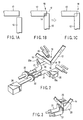
- FIGS. 1A to 1C are plan views individually schematically showing processes of joining belt-shaped glass sheets according to an embodiment of this invention;
- FIG. 2 is a perspective view showing a thermal softening process of the joining method and a joining apparatus;
- FIG. 3 is a perspective view showing a clamping process of the joining method;
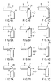
- FIGS. 4A to 4C are plan views individually schematically showing processes of joining belt-shaped glass sheets according to another embodiment of this invention;
- FIGS. 5A to 5C are plan views individually schematically showing processes of joining belt-shaped glass sheets according to still another embodiment of this invention;
- FIGS. 6A to 6C are plan views individually schematically showing processes of joining belt-shaped glass sheets according to another embodiment of this invention;
- FIGS. 7A to 7C are plan views individually schematically showing processes of joining belt-shaped glass sheets according to another embodiment of this invention;
- FIGS. 8A to 8B are plan views individually schematically showing processes of joining belt-shaped glass sheets according to another embodiment of this invention;
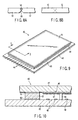
- FIG. 9 is a perspective view showing an image display apparatus with a glass frame;
- FIG. 10 is a sectional view taken along line X-X of FIG. 9; and
- FIG. 11 is a front view showing a glass frame manufacturing apparatus according to an embodiment of this invention.
-
- Embodiments of this invention will now be described with reference to the drawings. Basic processes of a joining method and the fundamental configuration of a joining apparatus according to the present invention will be described first.
- First, as shown in FIGS. 1A and 1B, two belt-
shaped glass sheets shaped glass sheets - Subsequently, the two belt-
shaped glass sheets rectangular corner portion 18, for example. As this is done, the respective end portions of the belt-shaped glass sheets are located overlapping each other within the range of the glass sheet width. In this case, the area oflap portions 14 influences the shape of the corner portion that is defined by the two joined belt-shaped glass sheets lap portions 14 should be within half the glass sheet width. Surplus glass that is produced as the end portions are fused together can be discharged into anoutside gap portion 16 that is formed as the superposed end portions are staggered within the range of the glass sheet width. - According to the present joining method, as shown in FIG. 2, the belt-
shaped glass sheets corner portion 18 faces vertically upward. In this state, the respective end portions of the belt-shaped glass sheets burners 19. - The moment the belt-
shaped glass sheets respective lap portions 14 are instantaneously clamped at least once between a pair of pressure dies 20 from both sides in the thickness direction of the belt-shaped glass sheets, as shown in FIG. 3. Thereupon, thelap portions 14 are fused and joined together, and the thickness of the resulting joint is made substantially equal to the thickness of the belt-shaped glass sheets. Further, the joint is flattened so that it is substantially flush with the surface of the belt-shaped glass sheets. - The pressure dies 20 are in the form of a rectangular box each and have their respective
flat clamping surfaces 20a that engage therespective lap portions 14 of the belt-shaped glass sheets rockable arms 21, individually, and are supported so as to be movable between an open position shown in FIG. 3, in which they are spaced, and a clamping position shown in FIG. 3, in which theirrespective clamping surfaces 20a face each other with a gap substantially equal to the thickness of the belt-shaped glass sheets between them.Gears 22 are fixed individually on the twoarms 21 and are in mesh with each other. - A
drive mechanism 24, which includes a motor, a gear mechanism, etc. (not shown), is connected to one of thearms 21. When the onearm 21 is rotated by means of thedrive mechanism 24, the twoarms 21 rock simultaneously, and the pair of pressure dies 20 are moved between the open position and the clamping position. Thus, therespective lap portions 14 of the belt-shapedglass sheets lap portions 14 located between the pressure dies. - Each pressure die 20 is formed of, for example, stainless steel, cast iron, etc., and its surface is coated with a carbon layer or the like to which glass cannot easily adhere.
- If the
lap portions 14 are instantaneously clamped by means of the pressure dies 20 after the belt-shaped glass sheets are thermally softened, softened surplus glass pools on the interior-angle side of thecorner portion 18. Therefore, the curvature shape of thecorner portion 18 obtained after joining may possibly undergo dispersion. According to the joining method of the present embodiment, as described above, therefore, the belt-shapedglass sheets corner portion 18 faces vertically upward. By thermally softening thelap portions 14 in this state, the softened glass at the interior-angle portion is caused to flow downward by the agency of gravity, and it can move into thegap portion 16. Thus, the glass can be restrained from projecting on the inside of thecorner portion 18, so that a joint that has uniform thickness and curvature shape can be obtained. - In order to clamp the glass of the thermally softened
lap portions 14 between the pressure dies 20, thereby correcting the thickness and shape of the joint, on the other hand, the viscosity of the glass must be low enough to cause a viscous flow with ease. If the belt-shaped glass sheets have small heat capacity, in particular, the softened glass surface is quickly deprived of heat or cooled to be solidified when it is touched by the metallic pressure dies 20. Accordingly, it is hard to smoothly correct the thickness and flatness of the joint, and cracks are easily caused by thermal shock. - According to the joining method of the present embodiment, therefore, the
lap portions 14 are instantaneously clamped by means of the pressure dies 20 to correct the thickness distribution and curvature shape to avoid the surface temperature of thelap portions 14 of the belt-shaped glass sheets that are thermally softened being lowered to the distortion point or below. In this case, the time of contact between the pressure dies 20 and the belt-shaped glass sheets, that is, clamping time, is an essential factor. If this clamping time is long, cracks are easily caused by thermal shock. Therefore, the clamping time for each cycle is adjusted to about 2 seconds or less. If sufficient effects of joining and correction cannot be obtained by one cycle of clamping, the aforesaid thermal softening and instantaneous clamping are repeated again. - Thus, the respective end portions of the belt-shaped
glass sheets - The inside and outside curvature shape of the
corner portion 18 of the joint can be freely adjusted by joining the belt-shapedglass sheets glass sheets notch 26 formed at least in one end corner, are superposed on each other, as shown in FIGS. 4A to 4C, 5A to 5C, and 6A to 6C. Thenotch 26 may be formed on either side, outside or inside, of thecorner portion 18, and its depth of cut can be also set freely. - Alternatively, the belt-shaped
glass sheets glass sheets notch 26 formed in each end corner, are superposed on each other, as shown in FIGS. 7A to 7C. In this case, the inside and outside curvature shapes of thecorner portion 18 of the joint can be also adjusted freely. - Further, the belt-shaped glass sheets may be joined at any desired angle instead of being joined at right angles to each other as in the foregoing embodiment. As shown in FIGS. 8A and 8B, for example, the belt-shaped glass sheets may be joined so as to be aligned in a straight line.
- The following is a detailed description of an embodiment in which the joining method and the joining apparatus described above are applied to a manufacturing method and a manufacturing apparatus for a glass frame that is formed of a plurality of belt-shaped glass sheets.
- The manufacturing method and the manufacturing apparatus described herein are used to manufacture a glass frame that serves as a sidewall of an envelope of a field emission display (hereinafter referred to as FED) as an image display device.
- An FED having a sidewall formed of a glass frame will be described first.
- As shown in FIGS. 9 and 10, the FED is provided with a
front substrate 41 and arear substrate 42, which is formed of a rectangular glass sheet each. These substrates are opposed to each other with a gap of 1 to 2 mm between them. Therear substrate 42 is larger in size than thefront substrate 41, andwires 44 for inputting video signals (mentioned later) are drawn out of its outer peripheral portion. - The respective peripheral edge portions of the
front substrate 41 and therear substrate 42 are joined together with a rectangular frame-shapedsidewall 43 of glass between them. Thus, the substrates form a flat,rectangular vacuum envelope 40 that maintains a vacuum inside. Therear substrate 42 and thesidewall 43 are joined together by means of frittedglass 50, while thefront substrate 41 and thesidewall 43 are joined together by means of a sealingmaterial 52, such as fritted glass or low-melting metal. - In order to support atmospheric pressure load that acts on the
front substrate 41 and therear substrate 42, a plurality of plate-shapedsupport members 45 are provided in thevacuum envelope 40. Thesupport members 45 need not always be plate-shape and may alternatively be columnar. - A
phosphor screen 46 that functions as an image display surface is formed on the inner surface of thefront substrate 41. Thephosphor screen 46 is formed by arranging red, green, and blue phosphor layers and black nonreflective layers that are situated between the phosphor layers. A metal backlayer 47 of, e.g., aluminum is formed on thephosphor screen 46. - A large number of
electron emitting elements 48 that individually emit electron beams are provided on the inner surface of therear substrate 42. Theelectron emitting elements 48 serve as sources of electron emission that excite the phosphor layers of thephosphor screen 46. Theseelectron emitting elements 48 are arranged in a plurality of rows and a plurality of columns corresponding to individual pixels. - In the FED constructed in this manner, voltage is applied to the
electron emitting elements 48 by means of thewires 44 that are formed on therear substrate 42, whereupon j electron emitting elements emit electron beams toward thephosphor screen 46. Thus, the phosphor layers of thephosphor screen 46 are excited to glow and display an image. - The following is a description of a manufacturing method and a manufacturing apparatus for the rectangular glass frame that is used for the sidewall of the FED constructed in this manner.
- As shown in FIG. 11, this manufacturing apparatus comprises a rocking base 6 and a substantially
rectangular rack 5. The base 6 is rockably mounted on acenter shaft 28 that extends horizontally. Therack 5 is supported on the rocking base and located within a vertical plane. Therack 5, which functions as a glass sheet holding portion, is assembled from angles of light metal, such as aluminum. Four belt-shapedglass sheets 10, which are cut to accurate lengths that correspond to the long and short sides of the glass frame, are set individually on the side edge portions of therack 5 by means ofmagnetized metal retainers 23 so as to form a rectangular frame. As this is done, each belt-shapedglass sheet 10 is set so that its end portion is superposed on an end portion of its adjacent belt-shaped glass sheet at right angles thereto, as shown in FIG. 1B. - A pair of
burners 19, a pair of pressure dies 20, and thedrive mechanism 24, which are shown in FIGS. 2 and 3, are located in a joining position A indicated by symbol A in FIG. 11, and along with therack 5, constitute the manufacturing apparatus. - In manufacturing the rectangular glass frame by joining the respective lap portions of the belt-shaped
glass sheets 10 that are set on therack 5 in the aforesaid manner, it is efficient and advantageous to automation to join the four corner joins in the one joining position A. In the case of a square glass frame, therack 5 on which the belt-shaped glass sheets are set is rotated around its center of rotation or the intersection of diagonal lines. By doing this, the individual corner portions of the glass frame can be successively moved to the one joining position A as they are joined together. - In the case of an oblong glass frame, its two sets of corner portions require
different centers 7a and 7b of rotation. In working the frame in the one joining position A, therefore, therack 5 on which the belt-shaped glass sheets are set is moved parallel to the rotating base 6, whereby the position of the center of rotation relative to the two sets of corner portions is changed. - Thereupon, the
rack 5 is provided with two supportingrods 8 that extend parallel to its long sides. These supporting rods are slidably supported on a pair of supportingframes 30, which are fixed to the rocking base 6, by means of fourbearings 9. Thus, therack 5 is supported for translation parallel to its long sides. The supportingrods 8 and the supportingframes 30 constitute a sliding mechanism. - For one set of corner portions, therefore, the rotating base 6 is rotated for 90° to joint the corner portions. For the other set of corner portions, the
rack 5 is translated to adjust the position of the center of rotation of therack 5 to 7a or 7b, and the rocking base 6 is rotated to joint the corner portions thereafter. Thus, all the four corner portions can be joined in the one joining position A. - The shift of the position of the center of rotation of the
rack 5, that is, the translation of therack 5, can be carried out in the following manner. A switching handle 15 on therack 5 is thrown down on one side to drivegears cable 19 that is stretched via fourpulleys 17 on therack 5 wound up by means of apulley 14 that is linked to thegear 13. - In manufacturing the glass frame, the position of the
rack 5 is first adjusted so that the center 7a of rotation is aligned with thecenter shaft 28 of the rocking base 6, as shown in FIG. 11. Thereafter, the rocking base 6 is rocked so that the corner portions to be joined are located in the joining position A. Then, astopper 34 is inserted into one of recesses that are formed in the peripheral edge of the rocking base 6 at intervals of 90° , whereby the rocking base and therack 5 are fixed. - As shown in FIGS. 2 and 3, the joining work in the joining position A is carried out in a manner such that the joins are thermally softened from both sides by means of the
burners 19 with the interior-angle side of the corner portions of the joins vertically upward, and the joins are instantaneously clamped by means of the pair of pressure dies 20. If the target joins cannot be formed by one cycle of clamping, the thermal softening operation and instantaneous clamping should only be repeated several times as required. - After joining of one corner portion is finished, the
stopper 34 is disengaged to allow the rocking base 6 to rotate 90° , and the other corner portion is set in the joining position A. After the rocking base 6 and therack 5 are fixed again by means of thestopper 34, joining the other corner portion is executed. - In fusing together the other sets of corner portions that constitute the glass frame, the switching
handle 15 is thrown down on other side to translate therack 5 to a position such that the position of thecenter 7b of rotation of therack 5 coincides with thecentral shaft 28 of the rocking base 6. After the position of the center of rotation is adjusted, the two corner portions are successively joined in the joining position A by the same method as aforesaid. Thereupon, the thin rectangular glass frame is completed. - According to the manufacturing method and manufacturing apparatus for the glass frame constructed in this manner, the respective end portions of the belt-shaped glass sheets can be securely fused and joined together at the corner portions of the glass frame, and the thickness of the joins can be made substantially equal to those of any other parts of the belt-shaped glass sheets so that the whole glass frame is flat. Thus, a perfect horizontal surface can be maintained, and the glass frame can be obtained having uniform thickness and width and accurate dimensions. By manufacturing the envelope of the image display device using the glass as its sidewall, moreover, the resulting image display device has its peripheral portion hermetically sealed and is improved in reliability.
- This invention is not limited to the embodiment described above, and various modifications may be effected therein without departing from the scope of the invention. The joining method and the joining apparatus are not limited to the manufacture of glass frames, and are also applicable to the manufacture of various glass products. Further, this invention is not limited to the manufacture of rectangular glass frames, but is also applicable to the manufacture of glass frames of different shapes, such as triangular ones, pentagonal ones, etc.
- According to this invention, as described in detail herein, there may be provided a joining method and a joining apparatus for belt-shaped glass sheets, whereby the belt-shaped glass sheets can be easily joined with high flatness. Further, there may be obtained a manufacturing method and a manufacturing apparatus, whereby a glass frame free from warp or wrinkles and having uniform thickness and width and high flatness can be manufactured, and a manufacturing method and a manufacturing apparatus for an image display device having a glass frame.
Claims (15)
- A method for joining end portions of belt-shaped glass sheets, comprising:thermally softening the end portions of the belt-shaped glass sheets after locating the end portions so that the end portions overlap each other within the range of the glass sheet width; andclamping lap portions of the thermally softened end portions at least once from both sides in the thickness direction of the belt-shaped glass sheets, thereby joining the lap portions together to adjust the lap portions to the thickness of the belt-shaped glass sheets.
- A method for joining belt-shaped glass sheets according to claim 1, wherein the thermally softened end portions are clamped at least once for a clamping time of about 2 seconds or less.
- A method for joining belt-shaped glass sheets according to claim 1, wherein the end portions are superposed on each other so that the belt-shaped glass sheets form corner portions, the belt-shaped glass sheets are then held substantially within a vertical plane with the inside of the corner portions vertically upward, and the end portions are then thermally softened and clamped.
- A joining method for belt-shaped glass sheets according to claim 3, wherein the end portions of the belt-shaped glass sheets are superposed on each other with end corners of the belt-shaped glass sheets partially notched.
- A joining apparatus which joins the end portions of belt-shaped glass sheets, comprising:a glass sheet holding portion which holds a plurality of belt-shaped glass sheets so that the end portions thereof overlap each other within the range of the glass sheet width;a heating mechanism which thermally softens the end portions of the held belt-shaped glass sheets; anda clamping mechanism configured to clamp lap portions of the thermally softened end portions from both sides in the thickness direction of the belt-shaped glass sheets, thereby joining the lap portions together to adjust the lap portions to the thickness of the belt-shaped glass sheets.
- A joining apparatus according to claim 5, wherein the clamping mechanism includes a pair of pressure dies movable between a clamping position, in which the dies face each other across a gap substantially equal to the thickness of the belt-shaped glass sheets, and an open position, in which the dies are spaced, and a drive mechanism which moves the pair of pressure dies from the open position to the clamping position with the lap portions of the belt-shaped glass sheets situated between the pair of pressure dies so that the lap portions are clamped by means of the pressure dies.
- A joining apparatus according to claim 6, wherein the glass sheet holding portion includes a rack, which holds the belt-shaped glass sheets substantially flush with one another in a manner such that the belt-shaped glass sheets extend across one another and that the end portions are superposed on each other so that the belt-shaped glass sheets form corner portions, and a base which supports the rack so that the belt-shaped glass sheets are situated substantially within a vertical plane with the inside of the corner portions vertically upward and that the lap portions are situated between the pair of pressure dies.
- A method of manufacturing a glass frame, comprising:holding a plurality of belt-shaped glass sheets substantially flush with one another in the form of a frame and locating the end portions of each two adjacent belt-shaped glass sheets so that the end portions overlap each other within the range of the glass sheet width;thermally softening the end portions of the belt-shaped glass sheets; andclamping lap portions of the thermally softened end portions at least once from both sides in the thickness direction of the belt-shaped glass sheets, thereby joining the lap portions together to adjust the lap portions to the thickness of the belt-shaped glass sheets.
- A method manufacturing for a glass frame according to claim 8, wherein the thermally softened end portions are clamped at least once for a clamping time of about 2 seconds or less.
- A method for manufacturing a glass frame according to claim 8, wherein the belt-shaped glass sheets are held substantially within a vertical plane in a manner such that the inside of corner portions defined by the end portions of the belt-shaped glass sheets faces vertically upward, and the end portions are thermally softened and clamped.
- A manufacturing apparatus which manufactures a glass frame by joining the end portions of belt-shaped glass sheets, comprising:a glass sheet holding portion which holds a plurality of belt-shaped glass sheets so that the end portions thereof overlap each other within the range of the glass sheet width, the belt-shaped glass sheets being arranged substantially flush with one another in the form of a frame;a heating mechanism which thermally softens the end portions of the held belt-shaped glass sheets; anda clamping mechanism which clamps lap portions of the thermally softened end portions from both sides in the thickness direction of the belt-shaped glass sheets, thereby joining the lap portions together to adjust the lap portions to the thickness of the belt-shaped glass sheets.
- A manufacturing apparatus according to claim 11, wherein the clamping mechanism includes a pair of pressure dies movable between a clamping position, in which the dies face each other across a gap substantially equal to the thickness of the belt-shaped glass sheets, and an open position, in which the dies are spaced, and a drive mechanism which moves the pair of pressure dies from the open position to the clamping position with the lap portions of the belt-shaped glass sheets situated between the pair of pressure dies so that the lap portions are clamped by means of the pressure dies.
- A manufacturing apparatus according to claim 11, further comprising a base which supports the rack so that the belt-shaped glass sheets are situated substantially within a vertical plane, are rockable around a substantially horizontal axis of rotation, and can move the end portions of the belt-shaped glass sheets to a given joining position, and a sliding mechanism which supports the rack for movement in the longitudinal direction of one of the belt-shaped glass sheets with respect to the base.
- A method for manufacturing an image display apparatus, which comprises an envelope, having a front substrate and a rear substrate opposed to each other and a sidewall in the form of a rectangular glass frame located between the respective peripheral portions of the front substrate and the rear substrate, and a plurality of elements arranged in the envelope, comprising:holding a plurality of belt-shaped glass sheets substantially flush with one another in the form of a frame and locating the end portions of each two adjacent belt-shaped glass sheets so that the end portions overlap each other within the range of the glass sheet width;thermally softening the overlapping end portions of the belt-shaped glass sheets; andclamping lap portions of the thermally softened end portions at least once from both sides in the thickness direction of the belt-shaped glass sheets, thereby joining the lap portions together to adjust the lap portions to the thickness of the belt-shaped glass sheets and forming the sidewall.
- A manufacturing apparatus for an image display apparatus, which comprises an envelope, having a front substrate and a rear substrate opposed to each other and a sidewall in the form of a rectangular glass frame located between the respective peripheral portions of the front substrate and the rear substrate, and a plurality of elements arranged in the envelope, comprising:a glass sheet holding portion which holds a plurality of belt-shaped glass sheets so that the end portions thereof overlap each other within the range of the glass sheet width, the belt-shaped glass sheets being arranged substantially flush with one another in the form of a frame and constituting the glass frame;a heating mechanism which thermally softens the end portions of the held belt-shaped glass sheets; anda clamping mechanism which clamps lap portions of the thermally softened end portions from both sides in the thickness direction of the belt-shaped glass sheets, thereby joining the lap portions together to adjust the lap portions to the thickness of the belt-shaped glass sheets.
Applications Claiming Priority (3)
| Application Number | Priority Date | Filing Date | Title |
|---|---|---|---|
| JP2001275519 | 2001-09-11 | ||
| JP2001275519 | 2001-09-11 | ||
| PCT/JP2002/009234 WO2003029157A1 (en) | 2001-09-11 | 2002-09-10 | Method and device for joining band-shaped glass panes, method and device for manufacturing glass frame, and method and device for manufacturing image display device with glass frame |
Publications (1)
| Publication Number | Publication Date |
|---|---|
| EP1435341A1 true EP1435341A1 (en) | 2004-07-07 |
Family
ID=19100371
Family Applications (1)
| Application Number | Title | Priority Date | Filing Date |
|---|---|---|---|
| EP02800229A Withdrawn EP1435341A1 (en) | 2001-09-11 | 2002-09-10 | Method and device for joining band-shaped glass panes, method and device for manufacturing glass frame, and method and device for manufacturing image display device with glass frame |
Country Status (5)
| Country | Link |
|---|---|
| US (1) | US20040172975A1 (en) |
| EP (1) | EP1435341A1 (en) |
| KR (1) | KR100571074B1 (en) |
| CN (1) | CN1277771C (en) |
| WO (1) | WO2003029157A1 (en) |
Cited By (1)
| Publication number | Priority date | Publication date | Assignee | Title |
|---|---|---|---|---|
| CH706648A1 (en) * | 2012-06-27 | 2013-12-31 | Engeler Ag Glaswelt | Three-dimensional molten glass body as a glass lamp body, comprises first glass wall having first side edge and second glass wall having second side edge, which are mutually arranged at an angle and are fused together |
Families Citing this family (9)
| Publication number | Priority date | Publication date | Assignee | Title |
|---|---|---|---|---|
| KR20070006861A (en) * | 2004-05-10 | 2007-01-11 | 가부시끼가이샤 도시바 | Manufacturing method of glass frame, manufacturing apparatus and joining method of strip-shaped glass plate |
| TWI626223B (en) | 2010-11-30 | 2018-06-11 | 康寧公司 | Glass ribbons and methods of splicing first glass ribbon portion to second member |
| JP5657586B2 (en) * | 2011-03-30 | 2015-01-21 | Hoya株式会社 | Method for producing cover glass blank for electronic device and method for producing cover glass for electronic device |
| TWI591040B (en) | 2012-10-22 | 2017-07-11 | 康寧公司 | Glass webs and methods of splicing |
| JP6505975B2 (en) | 2013-03-15 | 2019-04-24 | スコット コーポレーションSchott Corporation | Optical bonding and formed products using low softening point optical glass for infrared optics |
| EP3959163A4 (en) * | 2019-04-15 | 2024-05-22 | Sonoco Development, Inc. | Web splice |
| CN110156348B (en) * | 2019-05-06 | 2024-01-23 | 中建材玻璃新材料研究院集团有限公司 | A mobile phone glass middle frame and back cover sealing mold and its use method |
| JP2023514044A (en) * | 2020-02-06 | 2023-04-05 | テスラ,インコーポレイテッド | Automotive glass structure with feature lines and associated manufacturing method |
| CN114085034A (en) * | 2021-11-10 | 2022-02-25 | 华为技术有限公司 | Welding apparatus and welding method |
Family Cites Families (12)
| Publication number | Priority date | Publication date | Assignee | Title |
|---|---|---|---|---|
| US2049528A (en) * | 1935-07-03 | 1936-08-04 | Pittsburgh Plate Glass Co | Double glazed window |
| US3223504A (en) * | 1963-10-07 | 1965-12-14 | Pittsburgh Plate Glass Co | Method of bending glass sheets |
| US3425147A (en) * | 1966-01-26 | 1969-02-04 | Guilherme S Marx | Display frame |
| GB1206751A (en) * | 1966-10-14 | 1970-09-30 | Bitumen Ind Ind Ltd | Improvements in or relating to sealing double glazing units |
| US4228993A (en) * | 1978-05-01 | 1980-10-21 | Ppg Industries, Inc. | Sheet orienting and transporting frame |
| JPS6027627A (en) * | 1983-07-19 | 1985-02-12 | Ueno Seisakusho:Kk | Forming of mold frame using glass base |
| JPS60210550A (en) * | 1984-04-03 | 1985-10-23 | Nec Kagoshima Ltd | Method for forming glass spacer |
| EP0351739B1 (en) * | 1988-07-18 | 1994-12-14 | Asahi Glass Company Ltd. | Method of and apparatus for bending glass plates for a laminated glass |
| JPH04305038A (en) * | 1991-01-10 | 1992-10-28 | Nec Corp | Metallic cylindrical glass molded body and production thereof |
| JP2000311630A (en) * | 1999-02-25 | 2000-11-07 | Canon Inc | Vacuum container, method of manufacturing the same, and flat panel image display device provided with the vacuum container |
| US6616025B1 (en) * | 2000-08-31 | 2003-09-09 | Corning Incorporated | Automated flat glass separator |
| US6732548B2 (en) * | 2001-07-12 | 2004-05-11 | Valentine H. Reagh | Ornamental glass object and method of fabrication |
-
2002
- 2002-09-10 KR KR1020047003512A patent/KR100571074B1/en not_active Expired - Fee Related
- 2002-09-10 WO PCT/JP2002/009234 patent/WO2003029157A1/en not_active Ceased
- 2002-09-10 CN CNB028176510A patent/CN1277771C/en not_active Expired - Fee Related
- 2002-09-10 EP EP02800229A patent/EP1435341A1/en not_active Withdrawn
-
2004
- 2004-03-11 US US10/796,961 patent/US20040172975A1/en not_active Abandoned
Non-Patent Citations (1)
| Title |
|---|
| See references of WO03029157A1 * |
Cited By (1)
| Publication number | Priority date | Publication date | Assignee | Title |
|---|---|---|---|---|
| CH706648A1 (en) * | 2012-06-27 | 2013-12-31 | Engeler Ag Glaswelt | Three-dimensional molten glass body as a glass lamp body, comprises first glass wall having first side edge and second glass wall having second side edge, which are mutually arranged at an angle and are fused together |
Also Published As
| Publication number | Publication date |
|---|---|
| CN1553880A (en) | 2004-12-08 |
| CN1277771C (en) | 2006-10-04 |
| KR100571074B1 (en) | 2006-04-14 |
| WO2003029157A1 (en) | 2003-04-10 |
| KR20040034719A (en) | 2004-04-28 |
| US20040172975A1 (en) | 2004-09-09 |
Similar Documents
| Publication | Publication Date | Title |
|---|---|---|
| EP1078386B1 (en) | Seal material and a method for forming seal material | |
| US20040172975A1 (en) | Joining method and joining apparatus for joining belt-shaped glass sheets, manufacturing method and manufacturing apparatus for glass frame, and manufacturing method and manufacturing apparatus for image display apparatus with glass frame | |
| JP2006066079A (en) | Envelope manufacturing method and apparatus | |
| TWI286335B (en) | Method and equipment for manufacturing glass frame, and joining method of belt glass plate | |
| JP2012226978A (en) | Manufacturing method of air tight container and image display apparatus | |
| US6126505A (en) | Composite frit frame with backbone | |
| US20070212972A1 (en) | Method of manufacturing image display device | |
| JP2003160347A (en) | Bonding method and bonding apparatus for bonding belt-shaped glass plates, glass frame manufacturing method and manufacturing apparatus, and image display apparatus including glass frame manufacturing method and manufacturing apparatus | |
| JP2005320205A (en) | Method for joining strip glass plate and method for producing glass frame | |
| JP2007039260A (en) | Method for manufacturing stretched glass member, method for manufacturing spacer, and method for manufacturing image display device | |
| KR930004683B1 (en) | Manufacturing Method of Flat Panel Display | |
| JP2001229825A (en) | Vacuum envelope manufacturing method, manufacturing apparatus, image display apparatus manufacturing method, manufacturing apparatus, vacuum envelope, and image display apparatus | |
| JPH06196094A (en) | Manufacture of vacuum display device | |
| JPH10334830A (en) | Cathode ray tube and method of manufacturing the same | |
| CN1946641A (en) | Manufacturing method and device for glass frame and bonding method for strip-shaped glass plates | |
| JPH08329861A (en) | Image forming device | |
| EP0948025A2 (en) | Cathode ray tube and method of manufacturing the same | |
| JP2013004193A (en) | Airtight container manufacturing method | |
| JPS62170128A (en) | Manufacture of cover glass | |
| JP2002072903A (en) | Method and apparatus for manufacturing display panel | |
| JP2007035302A (en) | Airtight container, manufacturing method of the same, and display device | |
| JP2004288649A (en) | Method for manufacturing rear substrate for plasma display panel | |
| JP2004095220A (en) | Jig for manufacturing image display device and method for manufacturing image display device using the same | |
| JP2002260561A (en) | Flat display panel and method of manufacturing the same | |
| JPH0512992A (en) | Method of manufacturing flat display device |
Legal Events
| Date | Code | Title | Description |
|---|---|---|---|
| PUAI | Public reference made under article 153(3) epc to a published international application that has entered the european phase |
Free format text: ORIGINAL CODE: 0009012 |
|
| 17P | Request for examination filed |
Effective date: 20040331 |
|
| AK | Designated contracting states |
Kind code of ref document: A1 Designated state(s): DE FR GB IT NL |
|
| STAA | Information on the status of an ep patent application or granted ep patent |
Free format text: STATUS: THE APPLICATION HAS BEEN WITHDRAWN |
|
| 18W | Application withdrawn |
Effective date: 20080220 |