EP1435313A1 - Retractor - Google Patents
Retractor Download PDFInfo
- Publication number
- EP1435313A1 EP1435313A1 EP03250045A EP03250045A EP1435313A1 EP 1435313 A1 EP1435313 A1 EP 1435313A1 EP 03250045 A EP03250045 A EP 03250045A EP 03250045 A EP03250045 A EP 03250045A EP 1435313 A1 EP1435313 A1 EP 1435313A1
- Authority
- EP
- European Patent Office
- Prior art keywords
- lockbar
- cut
- frame
- retractor
- edge
- Prior art date
- Legal status (The legal status is an assumption and is not a legal conclusion. Google has not performed a legal analysis and makes no representation as to the accuracy of the status listed.)
- Granted
Links
- 239000000463 material Substances 0.000 claims abstract description 13
- 229910000831 Steel Inorganic materials 0.000 claims abstract description 5
- 239000010959 steel Substances 0.000 claims abstract description 5
- CWYNVVGOOAEACU-UHFFFAOYSA-N Fe2+ Chemical compound [Fe+2] CWYNVVGOOAEACU-UHFFFAOYSA-N 0.000 claims abstract description 4
- 230000000694 effects Effects 0.000 description 2
- 230000002028 premature Effects 0.000 description 2
- 238000007373 indentation Methods 0.000 description 1
- 230000000284 resting effect Effects 0.000 description 1
Images
Classifications
-
- B—PERFORMING OPERATIONS; TRANSPORTING
- B60—VEHICLES IN GENERAL
- B60R—VEHICLES, VEHICLE FITTINGS, OR VEHICLE PARTS, NOT OTHERWISE PROVIDED FOR
- B60R22/00—Safety belts or body harnesses in vehicles
- B60R22/34—Belt retractors, e.g. reels
- B60R22/36—Belt retractors, e.g. reels self-locking in an emergency
Definitions
- the present invention relates to a retractor for a vehicle safety restraint seat belt.
- a safety restraint retractor traditionally comprises a pressed steel U-shaped frame within which is mounted a rotatable cylindrical spool serving as a reservoir for seat belt webbing.
- the spool rotates about its longitudinal axis to pay-out or wind-in webbing as required, but is biased towards a webbing wound position so as to maintain the safety belt securely across the body of a vehicle occupant without slack developing.
- the occupant is able to move around within limits, for example, to reach a glove compartment or radio controls.
- a sensor detects a sudden deceleration of the vehicle and locks the spool against further pay-out of webbing, thus securing the occupant against forward motion and preventing impact with internal parts of the vehicle.
- the spool is locked by means of a die cast non-ferrous lockbar mounted across the open part of the arms of the U-shaped frame.
- the lockbar pivots in cut-outs in the frame arms, into and out of its locking position.
- a U-shaped frame for a vehicle safety restraint retractor comprising two spaced arms of a material of a predetermined thickness and having a cut-out in each arm for receiving a lockbar, wherein the cut-out (2) has an edge comprising a land portion for supporting the lockbar, which portion is of a reduced thickness compared to the predetermined thickness to present a reduced surface area to the lockbar.
- the edge further comprises a second section which tapers or steps away from the land portion and from the cut-out.
- edge of the cut-out may be chamfered or otherwise cut-away or tapered in part.
- the material of the frame is pressed steel.
- the frame may be used in a retractor with a lockbar formed of die-cast non-ferrous material.
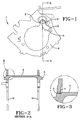
- FIG 1 one arm 9 of a U-shaped frame for a retractor is shown in side view and indicated by the reference 1.
- a cut-out 2 is provided in the upper part of the frame 2 and a lockbar 3 rests in this cut-out 2.
- the lockbar 3 comprises an elongate rod 4 passing through the cut-out 2 in the arm of the frame shown and also through a corresponding cut-out in the other arm of the frame 1 (seen in figure 2).
- the lockbar is pivotable in the cut-outs 2 between an unengaged position as shown, and a locking position in which the teeth 6 engage with teeth on a spool assembly to prevent rotation of the spool and thus prevent pay-out of seat belt webbing in the event of a crash.
- Figure 2 is a cross section through line A-A of figure 1 showing the two arms 9 of the frame 1 with the lockbar 3 resting on narrow lands 7 in the cut-outs 2.
- These narrow lands 7 lie on at least a part of the edge of each cut-out 2 to present a relatively sharp edge, ie small surface area to the rod 4 of the lockbar 3.
- These lands 7 generally will permanently contact the rod 4.
- Figure 3 shows an enlarged view of the area B of figure 2, in which the edge of each cut-out 2 has a second section 8 which tapers away from the land 7 in the region in which the lockbar 3 contacts the edge of the cut-out 2.
- the frame bearing second section 8 may alternatively step away from the land 7.
- the chamfer taper or step helps to prevent excessive indentation of the frame 1 into the lockbar 3 which may lead to premature failure of the lockbar 3 and thus of the retractor.
- This second section 8 comes into effect as the load increases and serves to reduce the contact pressure between the lockbar 3 and the frame 1.
- This invention can achieve an improvement in tensile load capacity of a safety restraint retractor with no additional parts, weight or cost.
Landscapes
- Engineering & Computer Science (AREA)
- Mechanical Engineering (AREA)
- Emergency Lowering Means (AREA)
- Automotive Seat Belt Assembly (AREA)
Abstract
Description
- The present invention relates to a retractor for a vehicle safety restraint seat belt.
- A safety restraint retractor traditionally comprises a pressed steel U-shaped frame within which is mounted a rotatable cylindrical spool serving as a reservoir for seat belt webbing. The spool rotates about its longitudinal axis to pay-out or wind-in webbing as required, but is biased towards a webbing wound position so as to maintain the safety belt securely across the body of a vehicle occupant without slack developing. The occupant is able to move around within limits, for example, to reach a glove compartment or radio controls. However in the event of a crash, a sensor detects a sudden deceleration of the vehicle and locks the spool against further pay-out of webbing, thus securing the occupant against forward motion and preventing impact with internal parts of the vehicle.
- The spool is locked by means of a die cast non-ferrous lockbar mounted across the open part of the arms of the U-shaped frame. The lockbar pivots in cut-outs in the frame arms, into and out of its locking position. Considerable tensile forces are transmitted to the frame during a crash incident and, to resist premature failure of the frame due to its inherent instability, thicker material and additional cross bracing are traditionally employed in the vicinity of the relevant area.
- However this extra material and cross bracing results in additional weight and cost of the frame assembly. It would be advantageous to stabilize the frame without the extra material and improve the tensile load capacity with no extra parts, weight or cost.
- According to the present invention there is provided a U-shaped frame for a vehicle safety restraint retractor comprising two spaced arms of a material of a predetermined thickness and having a cut-out in each arm for receiving a lockbar, wherein the cut-out (2) has an edge comprising a land portion for supporting the lockbar, which portion is of a reduced thickness compared to the predetermined thickness to present a reduced surface area to the lockbar.
- According to one embodiment of the present invention the edge further comprises a second section which tapers or steps away from the land portion and from the cut-out.
- Hence the edge of the cut-out may be chamfered or otherwise cut-away or tapered in part.
- Preferably the material of the frame is pressed steel. The frame may be used in a retractor with a lockbar formed of die-cast non-ferrous material.
- For a better understanding of the invention, and to show how the same may be carried into effect, reference will now be made to the accompanying drawings, in which:
- Figure 1 is a side view of a retractor frame assembly according to the present invention.
- Figure 2 is a cross section taken along line A-A in figure 1.
- Figure 3 is a close up of the area B of figure 2.
-
- In figure 1 one
arm 9 of a U-shaped frame for a retractor is shown in side view and indicated by thereference 1. A cut-out 2 is provided in the upper part of theframe 2 and alockbar 3 rests in this cut-out 2. Thelockbar 3 comprises anelongate rod 4 passing through the cut-out 2 in the arm of the frame shown and also through a corresponding cut-out in the other arm of the frame 1 (seen in figure 2). - Fixed to each end of the
rod 4 is alocking pawl 5 withlocking teeth 6. The lockbar is pivotable in the cut-outs 2 between an unengaged position as shown, and a locking position in which theteeth 6 engage with teeth on a spool assembly to prevent rotation of the spool and thus prevent pay-out of seat belt webbing in the event of a crash. - Figure 2 is a cross section through line A-A of figure 1 showing the two
arms 9 of theframe 1 with thelockbar 3 resting onnarrow lands 7 in the cut-outs 2. Thesenarrow lands 7 lie on at least a part of the edge of each cut-out 2 to present a relatively sharp edge, ie small surface area to therod 4 of thelockbar 3. Theselands 7 generally will permanently contact therod 4. As the load increases they will penetrate therod 4 and thelockbar 3 will be loaded with the increasing crash forces and experiences tensile loading along its length. This effectively holds theframe arms 9 together against their natural tendency to burst apart. - Figure 3 shows an enlarged view of the area B of figure 2, in which the edge of each cut-out 2 has a
second section 8 which tapers away from theland 7 in the region in which thelockbar 3 contacts the edge of the cut-out 2. - The frame bearing
second section 8 may alternatively step away from theland 7. The chamfer taper or step helps to prevent excessive indentation of theframe 1 into thelockbar 3 which may lead to premature failure of thelockbar 3 and thus of the retractor. Thissecond section 8 comes into effect as the load increases and serves to reduce the contact pressure between thelockbar 3 and theframe 1. - This invention can achieve an improvement in tensile load capacity of a safety restraint retractor with no additional parts, weight or cost.
Claims (7)
- A U-shaped frame (1) for a vehicle safety restraint retractor comprising two spaced arms (9) of a material of a predetermined thickness and having a cut-out (2) in each arm (9) for receiving a lockbar (3), wherein the cut-out (2) has an edge comprising a land portion (7) for supporting the lockbar (3), which portion is of a reduced thickness compared to the predetermined thickness to present a reduced surface area to the lockbar (3).
- A frame (1) according to claim 1 wherein the edge further comprises a second section (8) which tapers away from the land portion (7) and from the cut-out(2).
- A frame according to claim 1 wherein the second section (8) steps away from the land portion (7) and from the cut-out (2).
- A frame according to any one of the preceding claims wherein the material is pressed steel.
- A retractor for a vehicle safety restraint comprising a frame according to any one of the preceding claims.
- A retractor according to claim 5 further comprising a lockbar formed from die-cast non-ferrous material.
- A retractor according to any one of claims 5 to 7 when formed from pressed steel.
Priority Applications (3)
| Application Number | Priority Date | Filing Date | Title |
|---|---|---|---|
| EP03250045A EP1435313B1 (en) | 2003-01-03 | 2003-01-03 | Retractor |
| DE60313726T DE60313726T2 (en) | 2003-01-03 | 2003-01-03 | retractor |
| US10/683,705 US6957789B2 (en) | 2003-01-03 | 2003-10-14 | Seat belt retractor |
Applications Claiming Priority (1)
| Application Number | Priority Date | Filing Date | Title |
|---|---|---|---|
| EP03250045A EP1435313B1 (en) | 2003-01-03 | 2003-01-03 | Retractor |
Publications (2)
| Publication Number | Publication Date |
|---|---|
| EP1435313A1 true EP1435313A1 (en) | 2004-07-07 |
| EP1435313B1 EP1435313B1 (en) | 2007-05-09 |
Family
ID=32479947
Family Applications (1)
| Application Number | Title | Priority Date | Filing Date |
|---|---|---|---|
| EP03250045A Expired - Lifetime EP1435313B1 (en) | 2003-01-03 | 2003-01-03 | Retractor |
Country Status (3)
| Country | Link |
|---|---|
| US (1) | US6957789B2 (en) |
| EP (1) | EP1435313B1 (en) |
| DE (1) | DE60313726T2 (en) |
Families Citing this family (16)
| Publication number | Priority date | Publication date | Assignee | Title |
|---|---|---|---|---|
| US7263750B2 (en) | 2005-06-09 | 2007-09-04 | Amsafe, Inc. | Buckle assembly having single release for multiple belt connectors |
| WO2010037103A1 (en) | 2008-09-29 | 2010-04-01 | Amsafe, Inc. | Tensioning apparatuses for occupant restraint systems and associated systems and methods |
| US8469401B2 (en) | 2009-02-23 | 2013-06-25 | Amsafe, Inc. | Seat harness pretensioner |
| US8393645B2 (en) | 2009-11-02 | 2013-03-12 | Amsafe Commercial Products, Inc. | Devices for adjusting tension in seat belts and other restraint system webs, and associated methods |
| US8683666B2 (en) | 2009-11-04 | 2014-04-01 | Amsafe Commercial Products, Inc. | Restraint system buckle components having tactile surfaces, and associated methods of use and manufacture |
| US8627554B1 (en) | 2010-05-03 | 2014-01-14 | Amsafe, Inc. (Phoenix Group) | Buckle assemblies with swivel and dual release features and associated methods of use and manufacture |
| US8777323B2 (en) | 2010-07-20 | 2014-07-15 | Amsafe, Inc. | Restraint harnesses and associated methods of use and manufacture |
| USD655223S1 (en) | 2010-09-15 | 2012-03-06 | Amsafe Commercial Products, Inc. | Buckle assembly |
| USD661619S1 (en) | 2010-09-15 | 2012-06-12 | Amsafe Commercial Products, Inc. | Buckle assembly |
| US9022483B2 (en) | 2012-06-07 | 2015-05-05 | Shield Restraint Systems, Inc. | Seatbelt buckle tongue assembly |
| US9277788B2 (en) | 2013-02-19 | 2016-03-08 | Amsafe, Inc. | Dual release buckle assemblies and associated systems and methods |
| EP2958453A4 (en) | 2013-02-19 | 2016-07-27 | Amsafe Inc | Buckle assemblies with lift latches and associated methods and systems |
| WO2016100566A1 (en) | 2014-12-16 | 2016-06-23 | Shield Restraint Systems, Inc. | Web adjusters for use with restraint systems and associated methods of use and manufacture |
| US10604259B2 (en) | 2016-01-20 | 2020-03-31 | Amsafe, Inc. | Occupant restraint systems having extending restraints, and associated systems and methods |
| US9814282B2 (en) | 2016-02-02 | 2017-11-14 | Shield Restraint Systems, Inc. | Harsh environment buckle assemblies and associated systems and methods |
| US10611334B2 (en) | 2017-02-07 | 2020-04-07 | Shield Restraint Systems, Inc. | Web adjuster |
Citations (3)
| Publication number | Priority date | Publication date | Assignee | Title |
|---|---|---|---|---|
| EP0703124A1 (en) * | 1994-09-07 | 1996-03-27 | Takata Corporation | Seat belt retractor |
| US5924641A (en) * | 1997-02-21 | 1999-07-20 | Breed Automotive Technology, Inc. | Multi-level load limiting retractor |
| US6454201B1 (en) * | 1999-07-12 | 2002-09-24 | Trw Occupant Restraint Systems Gmbh & Co. Kg | Friction clutch and belt retractor with friction clutch |
Family Cites Families (1)
| Publication number | Priority date | Publication date | Assignee | Title |
|---|---|---|---|---|
| GB2347900A (en) * | 1999-03-15 | 2000-09-20 | Breed Automotive Tech | Seat Belt Retractor |
-
2003
- 2003-01-03 EP EP03250045A patent/EP1435313B1/en not_active Expired - Lifetime
- 2003-01-03 DE DE60313726T patent/DE60313726T2/en not_active Expired - Fee Related
- 2003-10-14 US US10/683,705 patent/US6957789B2/en not_active Expired - Fee Related
Patent Citations (3)
| Publication number | Priority date | Publication date | Assignee | Title |
|---|---|---|---|---|
| EP0703124A1 (en) * | 1994-09-07 | 1996-03-27 | Takata Corporation | Seat belt retractor |
| US5924641A (en) * | 1997-02-21 | 1999-07-20 | Breed Automotive Technology, Inc. | Multi-level load limiting retractor |
| US6454201B1 (en) * | 1999-07-12 | 2002-09-24 | Trw Occupant Restraint Systems Gmbh & Co. Kg | Friction clutch and belt retractor with friction clutch |
Also Published As
| Publication number | Publication date |
|---|---|
| US20040130137A1 (en) | 2004-07-08 |
| DE60313726T2 (en) | 2008-01-17 |
| DE60313726D1 (en) | 2007-06-21 |
| US6957789B2 (en) | 2005-10-25 |
| EP1435313B1 (en) | 2007-05-09 |
Similar Documents
| Publication | Publication Date | Title |
|---|---|---|
| EP1435313B1 (en) | Retractor | |
| US6913288B2 (en) | Load limiting structure for vehicle occupant restraint system | |
| US6592064B2 (en) | Self-locking belt roller having two retraction force limiting elements | |
| CN110077358B (en) | Seat belt pretensioner retractor assembly | |
| US20040094946A1 (en) | Restraint system tensioning device with load limiting capability | |
| EP1980458B1 (en) | Belt guide anchor and seat belt unit including the same | |
| PL170540B1 (en) | Belt tensioner for vehicle safety belts | |
| EP2813401B1 (en) | Pretensioner mechanism | |
| JP3454790B2 (en) | Multi-point pretensioner system | |
| KR100590990B1 (en) | Seat belt retractor | |
| US6045194A (en) | Belt retractor for incorporating in a fold-down type backrest | |
| US6267315B1 (en) | Seat belt retractor | |
| EP0888939B1 (en) | Retractor | |
| CN103987586B (en) | Belt pretensioner for restraint system | |
| US6416003B1 (en) | Belt reel for a belt retractor of a vehicle occupant restraint system | |
| JP3977839B2 (en) | Seat belt retractor with web sensor | |
| US9340182B2 (en) | Belt retractor for a vehicle safety belt | |
| US6241173B1 (en) | Belt retractor for a safety belt restraint system | |
| US20020140278A1 (en) | Seat restraint tensioner | |
| EP1285826A1 (en) | Retractor for a seat belt of a vehicle | |
| JP5530148B2 (en) | Seat belt device | |
| KR100465252B1 (en) | Lockbar for a seatbelt retractor | |
| CN100590007C (en) | Retaining structures and seat belt retractors | |
| JP2003019944A (en) | Seat belt device | |
| US4264091A (en) | Anchorage system for restraint belt |
Legal Events
| Date | Code | Title | Description |
|---|---|---|---|
| PUAI | Public reference made under article 153(3) epc to a published international application that has entered the european phase |
Free format text: ORIGINAL CODE: 0009012 |
|
| AK | Designated contracting states |
Kind code of ref document: A1 Designated state(s): AT BE BG CH CY CZ DE DK EE ES FI FR GB GR HU IE IT LI LU MC NL PT SE SI SK TR |
|
| AX | Request for extension of the european patent |
Extension state: AL LT LV MK RO |
|
| RAP1 | Party data changed (applicant data changed or rights of an application transferred) |
Owner name: KEY SAFETY SYSTEMS, INC. |
|
| 17P | Request for examination filed |
Effective date: 20040817 |
|
| AKX | Designation fees paid |
Designated state(s): DE FR GB IT |
|
| GRAP | Despatch of communication of intention to grant a patent |
Free format text: ORIGINAL CODE: EPIDOSNIGR1 |
|
| GRAS | Grant fee paid |
Free format text: ORIGINAL CODE: EPIDOSNIGR3 |
|
| GRAA | (expected) grant |
Free format text: ORIGINAL CODE: 0009210 |
|
| AK | Designated contracting states |
Kind code of ref document: B1 Designated state(s): DE FR GB IT |
|
| REG | Reference to a national code |
Ref country code: GB Ref legal event code: FG4D |
|
| REF | Corresponds to: |
Ref document number: 60313726 Country of ref document: DE Date of ref document: 20070621 Kind code of ref document: P |
|
| ET | Fr: translation filed | ||
| PLBE | No opposition filed within time limit |
Free format text: ORIGINAL CODE: 0009261 |
|
| STAA | Information on the status of an ep patent application or granted ep patent |
Free format text: STATUS: NO OPPOSITION FILED WITHIN TIME LIMIT |
|
| 26N | No opposition filed |
Effective date: 20080212 |
|
| PGFP | Annual fee paid to national office [announced via postgrant information from national office to epo] |
Ref country code: DE Payment date: 20090130 Year of fee payment: 7 |
|
| PGFP | Annual fee paid to national office [announced via postgrant information from national office to epo] |
Ref country code: GB Payment date: 20081211 Year of fee payment: 7 |
|
| PGFP | Annual fee paid to national office [announced via postgrant information from national office to epo] |
Ref country code: IT Payment date: 20090115 Year of fee payment: 7 |
|
| PGFP | Annual fee paid to national office [announced via postgrant information from national office to epo] |
Ref country code: FR Payment date: 20090106 Year of fee payment: 7 |
|
| GBPC | Gb: european patent ceased through non-payment of renewal fee |
Effective date: 20100103 |
|
| REG | Reference to a national code |
Ref country code: FR Ref legal event code: ST Effective date: 20100930 |
|
| PG25 | Lapsed in a contracting state [announced via postgrant information from national office to epo] |
Ref country code: FR Free format text: LAPSE BECAUSE OF NON-PAYMENT OF DUE FEES Effective date: 20100201 |
|
| PG25 | Lapsed in a contracting state [announced via postgrant information from national office to epo] |
Ref country code: DE Free format text: LAPSE BECAUSE OF NON-PAYMENT OF DUE FEES Effective date: 20100803 |
|
| PG25 | Lapsed in a contracting state [announced via postgrant information from national office to epo] |
Ref country code: GB Free format text: LAPSE BECAUSE OF NON-PAYMENT OF DUE FEES Effective date: 20100103 |
|
| PG25 | Lapsed in a contracting state [announced via postgrant information from national office to epo] |
Ref country code: IT Free format text: LAPSE BECAUSE OF NON-PAYMENT OF DUE FEES Effective date: 20100103 |