EP1435300A1 - Pneumatic tire - Google Patents
Pneumatic tire Download PDFInfo
- Publication number
- EP1435300A1 EP1435300A1 EP02801521A EP02801521A EP1435300A1 EP 1435300 A1 EP1435300 A1 EP 1435300A1 EP 02801521 A EP02801521 A EP 02801521A EP 02801521 A EP02801521 A EP 02801521A EP 1435300 A1 EP1435300 A1 EP 1435300A1
- Authority
- EP
- European Patent Office
- Prior art keywords
- crack
- groove
- tire
- narrow
- rubber material
- Prior art date
- Legal status (The legal status is an assumption and is not a legal conclusion. Google has not performed a legal analysis and makes no representation as to the accuracy of the status listed.)
- Withdrawn
Links
Images


Classifications
-
- B—PERFORMING OPERATIONS; TRANSPORTING
- B60—VEHICLES IN GENERAL
- B60C—VEHICLE TYRES; TYRE INFLATION; TYRE CHANGING; CONNECTING VALVES TO INFLATABLE ELASTIC BODIES IN GENERAL; DEVICES OR ARRANGEMENTS RELATED TO TYRES
- B60C11/00—Tyre tread bands; Tread patterns; Anti-skid inserts
- B60C11/03—Tread patterns
- B60C11/0306—Patterns comprising block rows or discontinuous ribs
- B60C11/0309—Patterns comprising block rows or discontinuous ribs further characterised by the groove cross-section
-
- B—PERFORMING OPERATIONS; TRANSPORTING
- B60—VEHICLES IN GENERAL
- B60C—VEHICLE TYRES; TYRE INFLATION; TYRE CHANGING; CONNECTING VALVES TO INFLATABLE ELASTIC BODIES IN GENERAL; DEVICES OR ARRANGEMENTS RELATED TO TYRES
- B60C11/00—Tyre tread bands; Tread patterns; Anti-skid inserts
- B60C11/01—Shape of the shoulders between tread and sidewall, e.g. rounded, stepped or cantilevered
-
- B—PERFORMING OPERATIONS; TRANSPORTING
- B60—VEHICLES IN GENERAL
- B60C—VEHICLE TYRES; TYRE INFLATION; TYRE CHANGING; CONNECTING VALVES TO INFLATABLE ELASTIC BODIES IN GENERAL; DEVICES OR ARRANGEMENTS RELATED TO TYRES
- B60C11/00—Tyre tread bands; Tread patterns; Anti-skid inserts
- B60C11/03—Tread patterns
- B60C11/13—Tread patterns characterised by the groove cross-section, e.g. for buttressing or preventing stone-trapping
-
- B—PERFORMING OPERATIONS; TRANSPORTING
- B60—VEHICLES IN GENERAL
- B60C—VEHICLE TYRES; TYRE INFLATION; TYRE CHANGING; CONNECTING VALVES TO INFLATABLE ELASTIC BODIES IN GENERAL; DEVICES OR ARRANGEMENTS RELATED TO TYRES
- B60C11/00—Tyre tread bands; Tread patterns; Anti-skid inserts
- B60C11/03—Tread patterns
- B60C11/13—Tread patterns characterised by the groove cross-section, e.g. for buttressing or preventing stone-trapping
- B60C11/1307—Tread patterns characterised by the groove cross-section, e.g. for buttressing or preventing stone-trapping with special features of the groove walls
- B60C11/1346—Tread patterns characterised by the groove cross-section, e.g. for buttressing or preventing stone-trapping with special features of the groove walls covered by a rubber different from the tread rubber
Definitions
- the present invention relates to a pneumatic tire capable of preventing uneven wear.
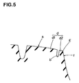
- a pneumatic tire formed at its tread surface a with an uneven wear-preventing narrow groove b extending from a tread edge E in a tire circumferential direction at inner side of a tire axial direction at a small distance from the tread edge E (e.g., Japanese Patent Application Laid-open No.H6-183209).
- This narrow groove b divides a rib d closer to the tread edge into a main rib part d1 inside the tire axial direction of the narrow groove b and a narrow rib part d2 formed between the narrow groove b and a buttress surface f and having low rigidity. Wear energy caused by running of a vehicle is concentrated on the narrow rib part d2 having the low rigidity, thereby restraining the uneven wear from proceeding toward the main rib part d1.
- the present invention has been accomplished in view of such a problem, and it is an object to provide a pneumatic tire capable of preventing the narrow rib part from becoming chipped and restraining the uneven wear from being generated for a long term based on an idea that a groove bottom surface of a narrow groove and an outer groove wall surface outside of the tire axial direction are formed of crack-resistant layer made of crack-resistant rubber material having excellent crack-resistance unlike a tread rubber, and thicknesses of the groove bottom surface and the groove wall surface are appropriately limited.
- a present invention described in claim 1 provides a pneumatic tire in which an uneven wear-preventing narrow groove is formed on a tread surface extending from a tread edge in a tire circumferential direction inside a tire axial direction at a small distance, wherein at least a groove bottom surface of the narrow groove and an outer groove wall surface outside of the tire axial direction are formed of crack-resistant layers made of crack-resistant rubber material having excellent crack-resistance, a thickness t1 of the crack-resistant layer at the groove bottom surface in a tire radial direction is set to 1 to 5mm, and a thickness t2 perpendicular to the outer groove wall surface at right angles is set to 1 to 6mm.
- An invention described in claim 2 is characterized in that, an inner groove wall surface of the narrow groove inside the tire axial direction is also formed of crack-resistant layer using the crack-resistant rubber material, the crack-resistant layer has substantially U-shaped cross section, a thickness t3 of the crack-resistant layer perpendicular to the inner groove wall surface is set to 2mm or less.
- An invention described in claim 3 is characterized in that, a tensile strength of the crack-resistant rubber material is 23 to 28MPa, and elongation at the time of cutting thereof is 550 to 620%.
- An invention described in claim 4 is characterized in that, in a state in which the crack-resistant rubber material is left in atmosphere of 100°C for 72 hours, the tensile strength thereof is 22MPa or higher and the elongation at the time of cutting is 480% or higher.
- Fig.1 is a partial sectional view of a pneumatic tire 1 of the embodiment
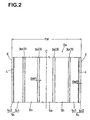
- Fig.2 is a development view showing a developed tread surface of the pneumatic tire 1.
- the pneumatic tire 1 includes a carcass 6 of a radial structure comprising a steel cord, and a belt layer 7 having four belt plies 7A to 7D comprising steel cord disposed outside of the carcass 6 and inside of a tread portion 2.
- the pneumatic tire 1 is a radial tire for heavy load used for a truck, a bus, a small truck and the like.
- the pneumatic tire 1 is formed and illustrated at its tread surface 2a with a plurality of circumferential main grooves 3 continuously extending in a tire circumferential direction, and uneven wear-preventing narrow grooves 4 extending from a tread edge E in the tire circumferential direction inside the tire axial direction at a small distance L therebetween.
- the circumferential main grooves 3 for example, comprise a pair of inner circumferential main grooves 3a and 3a formed on opposite sides of a tire equator C, and a pair of circumferential main grooves 3b and 3b formed on outer sides of the circumferential main grooves 3a and 3a.
- the grooves extend straightly in the drawing, but the groove may be appropriately bent into a zigzag shape, a wave shape or the like. It is preferable, for example, that a groove width GW1 of each of the circumferential main grooves 3 is about 2 to 8% of a tread width TW, and more preferably about 5 to 8% for ensuring the drainage.
- a groove depth GD1 (shown in Fig.1) of the circumferential main groove 3 is about 3 to 10% of the tread width TW, more preferably about 5 to 10%.
- the tread width TW is a distance between tread edges E and E in the tire axial direction.
- standard rim is a rim whose specification are determined for each tire.
- the rim is a "standard rim” in the case of JATMA
- the rim is a "Design Rim” in the case of TRA
- the rim is a "Measuring Rim” in the case of ETRTO.
- the term "standard internal pressure” is an air pressure whose specification are determined for each tire, and the standard internal pressure is a maximum air pressure in the case of JATMA, the standard internal pressure is a maximum value described in "TIRE LOAD LIMITS AT VARIOUS COLD INFLATION PRESSURE” in the case of TRA, and the standard internal pressure is an "INFLATION PRESSURE” in the case of ETRTO. If the tire is for a passenger car, the standard internal pressure is 180KPa.
- the tread portion 2 is divided into an inner rib part 5a formed between the inner circumferential main grooves 3a and 3a, intermediate rib parts 5b formed between the inner circumferential main grooves 3a and the outer circumferential main grooves 3b, and outer rib parts 5c formed between the circumferential main grooves 3b and the tread edges E.
- the rib parts 5a to 5c are formed as ribs continuously extending in the tire circumferential direction, but one or more rib parts can be formed as block lines by forming a lateral groove (not shown) crossing the rib parts, the rib parts can be formed as block patterns, or rib block patterns, or rag patterns can be formed alternatively.
- the narrow grooves 4 comprises an outer groove wall surface 4o located outside of the tire axial direction, an inner groove wall surface 4i located inside of the tire axial direction, and a groove bottom surface 4b for connecting the outer groove wall surface 4o and the inner groove wall surface 4i.
- the groove bottom surface 4b has an arc cross section in this embodiment.
- the outer groove wall surface 4o is away from the tread edge E inside the tire axial direction at a small distance L.
- each of the outer rib parts 5c is divided into a main rib part 5c1 inside the tire axial direction of the narrow grooves 4, and a narrow rib part 5c2 having a smaller width than the main rib part 5c1 formed outside of the tire axial direction of the narrow grooves 4.
- the narrow rib part 5c2 has lower rigidity than that of the main rib part 5c1, great slip or deformation is generated between the narrow rib part 5c2 and a road surface during running or tire under a load, the wear energy is concentrated on the narrow rib part 5c2, thereby preventing uneven wear from being generated in the main rib part 5c1.
- a shape of a cross section, a width, a depth and the like of the narrow grooves 4 are not especially limited, but it is preferable that a groove width GW2 is 20 to 25% of the groove width GW1 of the circumferential main groove 3, and more preferably 20 to 22%. It is preferable that a groove depth GD2 is 30 to 70% of the groove depth GD1 of the circumferential main groove 3, and more preferably 35 to 60%.
- the narrow lib part 5c2 is deformed substantially integrally with the main rib part 5c1 and it becomes difficult to concentrate the wear energy on the narrow lib part 5c2.
- the groove width GW2 of the narrow grooves 4 exceeds 25% of the groove width GW1 of the circumferential main groove 3 or if the groove depth GD2 of the narrow grooves 4 exceeds 70% of the groove depth GD1 of the circumferential main groove 3, it is not preferable because the narrow rib part 5c2 becomes chipped at an early stage.
- the small distance L is set to 3 to 10mm, and more preferably 5 to 7mm. If the small distance L is less than 3mm, the rigidity of the narrow rib part 5c2 is largely lowered, and there is a tendency that the narrow rib part 5c2 becomes chipped at an early stage. On the other hand, if the small distance L exceeds 10mm, the rigidity of the narrow rib part 5c2 is largely increased, and it becomes difficult to concentrate the wear energy on the narrow rib part 5c2.
- the groove bottom surface 4b, the outer groove wall surface 4o and the inner groove wall surface 4i on which large distortion is prone to act are formed of crack-resistant layers 9 having substantially U-shaped cross section.
- the crack-resistant layer 9 is formed of crack-resistant rubber material Cg having different composition from that of the tread rubber Tg and having excellent crack-resistance. Therefore, even if the narrow rib part 5c2 is largely deformed, it is possible to delay the generation of the cracks in the groove bottom surface 4b, and groove wall surfaces 4o and 4i, and it is possible to restrain the narrow rib part 5c2 from becoming chipped for a long term. With this arrangement, it is possible to maintain the uneven wear-preventing effect by the narrow rib part 5c2 for a long term.
- a thickness t1 of the crack-resistant layer 9 at the groove bottom surface 4b in the tire radial direction it is necessary to set a thickness t1 of the crack-resistant layer 9 at the groove bottom surface 4b in the tire radial direction to 1 to 5mm, and more preferably to 2 to 4mm. If the thickness t1 is less than 1mm, since the crack-resistant layer 9 is too thin, the distortion thereof at the groove bottom surface 4b can not sufficiently be moderated, and the crack can not be prevented from being generated. On the other hand, if the thickness t1 exceeds 5mm, there is a tendency that distortion generated in the groove bottom by fine deformation generated a groove cracks.
- the groove bottom surface 4b of the narrow grooves 4 is arc in shape, it is preferable that the thickness t1 inside the arc portion is secured.
- a thickness t2 which is perpendicular to the outer groove wall surface 4o of the crack-resistant layer 9 at right angles is set to 1 to 6mm, and more preferably to 2 to 5mm, and further preferably to 2 to 3mm. If the thickness t2 is less than 1mm, since the crack-resistant layer 9 is too thin, effect for moderating the distortion at the outer groove wall surface 4o is inferior, and it is not possible to restrain the crack from being generated. On the other hand, if the thickness t2 exceeds 6 mm, there is a tendency that uneven wear is prone to be generated in the narrow rib part 5c2 on the side of the narrow grooves 4.
- a ratio (tread portion t2/L) between the small distance L of the tire axial direction between the tread edge E and the outer groove wall surface 4o, and the thickness t2 which is perpendicular to the outer groove wall surface 4o of the crack-resistant layer 9 at right angles is set to 0.3 or higher. If the ratio (t2/L) is less than 0.3, there is a tendency that the narrow rib part 5c2 is prone to become chipped.
- a thickness t3 of the crack-resistant layer 9 which is perpendicular to the inner groove wall surface 4i at right angles is set to about 1 to 2mm. If the thickness t3 exceeds 2mm, the main rib part 5c1 is formed of two kinds of rubber materials having different rigidities, i.e., the tread rubber Tg and crack-resistant rubber material Cg, and due to the difference in rigidity, uneven wear is prone to be generated in the main rib part 5c1. Therefore, if the inner groove wall surface 4i is to be formed, it is preferable that the thickness of the crack-resistant layer is relatively thin, e.g., 2mm or less. From such a viewpoint, the inner groove wall surface 4i may not be formed with the crack-resistant layer as shown in Fig.4.
- a preferable example of material of the crack-resistant rubber material Cg is rubber polymer comprising natural rubber 100%.
- Preferable examples of additives to be added to the rubber polymer are, e.g., carbon black of SAF grade and/or silica.
- the crack-resistant rubber material Cg has a tensile strength of 23 to 28MPa, more preferably 25 to 28MPa and further preferably 27 to 28MPa, and elongation at the time of cutting is 550 to 620%, more preferably 550 to 590% and further preferably 580 to 590%.
- the tensile strength and elongation at the time of cutting of the rubber material are values measured in accordance with "Tensile testing method of vulcanized rubber" in JIS K6251.
- the tensile strength of the crack-resistant rubber material Cg is less than 23MPa, when the narrow rib part 5c2 receives great shear force or dragging force, the narrow grooves 4 easily becomes chipped in some cases. If the tensile strength of the crack-resistant rubber material Cg exceeds 28MPa on the other hand, there is an adverse possibility that the elongation at the time of cutting is reduced. If both the tensile strength and the elongation at the time of cutting are increased, heat is prone to be generated, and there is a no preferable tendency that damage is prone to be caused by thermal fatigue.
- the tensile strength of such a rubber material can be adjusted by kinds of carbon black and silica in the rubber composition and by composition amount.
- the elongation at the time of cutting of the crack-resistant rubber material Cg is less than 580%, when the narrow rib part 5c2 receives great shear force or dragging force, crack is prone to be generated in the groove surface of the narrow grooves 4.
- the elongation at the time of cutting of the rubber material can also be adjusted by kinds of carbon black and silica in the rubber composition and by composition amount.
- the crack-resistant rubber material Cg is a rubber material whose crack-resistance deterioration by an affect of ultraviolet ray and ozone is small. Therefore, it is preferable that in a state in which the crack-resistant rubber material Cg is left in atmosphere of 100°C for 72 hours, the tensile strength thereof is 22MPa or higher and the elongation at the time of cutting is 480% or higher. The tensile strength and the elongation at the time of cutting at that time were measured with the authority of the JIS test after the crack-resistant rubber material Cg was left in the above atmosphere.
- the tensile strength is less than 22MPa or the elongation at the time of cutting is less than 480% after the crack-resistant rubber material Cg is left in the atmosphere of 100°C for 72 hours, there is a tendency that the crack preventing effect at the groove bottom becomes small.
- the tensile strength and the elongation at the time of cutting at that time were also measured with the authority of the JIS test after the crack-resistant rubber material Cg was left in the above atmosphere.
- the above embodiment of the present invention has been explained based on the heavy load radial tire, but the invention should not be limited to this embodiment, and it is of course possible to apply the invention to a tire for a passenger car, and the narrow groove may be formed into a non-linear groove such as a zigzag groove or a wave-shaped groove, and the invention can variously be carried out.
- Heavy load radial tires having tire size of 11R22.5 were prototyped (for embodiments and a comparative example), and actual vehicle running test was carried out.
- the actual vehicle test was carried out in such a manner that the tires were assembled into rims of 7.50 ⁇ 22.5, internal pressure of 800kPa was charged, the tires were mounted to all wheels of a 10 tons flat body truck of 2DD, the vehicle was allowed to run through 40,000km on a predetermined running route (90% of expressway, 10% of road running), and state of the narrow groove was visually observed for every 10,000km.
- the circumferential main grooves had the same shape, and the groove width GW1 was set to 9mm, and the groove depth GD1 was set to 14mm.
- the tire specifications and test results are shown in Table 1.
- compositions of the crack-resistant rubber material and the tread rubber material are shown.
- Composition of crack-resistant rubber material Composition Parts by weight NR 100 Carbon black (SAF) 23 Carbon black (ISAF) 20 Carbon black (HAF) 13 Silica 13 Composition of tread rubber Composition Parts by weight NR 80 BR 20 Carbon black (ISAF) 49
- the groove bottom surface of the uneven wear-preventing narrow groove and the outer groove wall surface outside of the tire axial direction of the tire are formed of crack-resistant layers made of crack-resistant rubber materials having excellent crack-resistance, and the thicknesses of various portions are limited.
- the present invention is of help to restrain the narrow rib part formed between the narrow groove and the tread edge from becoming chipped, and to maintain the uneven wear-preventing effect for a long term.
Landscapes
- Engineering & Computer Science (AREA)
- Mechanical Engineering (AREA)
- Tires In General (AREA)
Abstract
In a pneumatic tire, a uneven wear-preventing narrow
groove 4 is formed on a tread surface 2a extending from a tread
edge E in a tire circumferential direction inside a tire axial
direction at a small distance L. At least a groove bottom
surface 4b of the narrow groove 4 and an outer groove wall surface
4o outside of the tire axial direction are formed of crack-resistant
layers 9 made of crack-resistant rubber material Cg
having excellent crack-resistance. A thickness t1 of the
crack-resistant layer 9 perpendicular to the groove bottom
surface 4b at right angles in a tire radial direction is set
to 1 to 5mm, and a thickness t2 perpendicular to the outer groove
wall surface 4o at right angles is set to 1 to 6mm.
Description
The present invention relates to a pneumatic tire capable
of preventing uneven wear.
As shown in Fig.5, there is proposed a pneumatic tire
formed at its tread surface a with an uneven wear-preventing
narrow groove b extending from a tread edge E in a tire
circumferential direction at inner side of a tire axial
direction at a small distance from the tread edge E (e.g.,
Japanese Patent Application Laid-open No.H6-183209). This
narrow groove b divides a rib d closer to the tread edge into
a main rib part d1 inside the tire axial direction of the narrow
groove b and a narrow rib part d2 formed between the narrow groove
b and a buttress surface f and having low rigidity. Wear energy
caused by running of a vehicle is concentrated on the narrow
rib part d2 having the low rigidity, thereby restraining the
uneven wear from proceeding toward the main rib part d1.
According to such a narrow rib part d2, however, since
the rigidity is small, relatively great bending deformation is
repeated inside and outside of the tire axial direction during
running, and the narrow rib part d2 receives great shear force
between a road surface and the narrow rib part d2 when the tire
rides over a curb or the vehicle turns. Therefore, a crack is
generated on a groove bottom surface of the narrow groove b at
a relatively early stage, a crack is proceeded into the rubber
from the former crack, and the narrow rib part d2 is damaged
in some cases. Especially in the case of a heavy load tire used
under a great load, a great shear force is generated in a tire
mounted to a trailer shaft at the time of turning motion of the
vehicle and thus, the damage is prone to appear clearly. If
the narrow rib part d2 becomes chipped, the uneven wear is prone
to be generated in the main rib part d1.
Thereupon, in order to prevent the narrow rib part d2 from
becoming chipped, it is conceived that a depth of the narrow
groove b is reduced and the rigidity of the narrow rib part d2
is increased. According to this method, however, it is
difficult to concentrate the wear energy on the narrow rib part
d2, and the suppression effect of the uneven wear is reduced.
The present invention has been accomplished in view of
such a problem, and it is an object to provide a pneumatic tire
capable of preventing the narrow rib part from becoming chipped
and restraining the uneven wear from being generated for a long
term based on an idea that a groove bottom surface of a narrow
groove and an outer groove wall surface outside of the tire axial
direction are formed of crack-resistant layer made of
crack-resistant rubber material having excellent crack-resistance
unlike a tread rubber, and thicknesses of the groove
bottom surface and the groove wall surface are appropriately
limited.
A present invention described in claim 1 provides a
pneumatic tire in which an uneven wear-preventing narrow groove
is formed on a tread surface extending from a tread edge in a
tire circumferential direction inside a tire axial direction
at a small distance, wherein at least a groove bottom surface
of the narrow groove and an outer groove wall surface outside
of the tire axial direction are formed of crack-resistant layers
made of crack-resistant rubber material having excellent
crack-resistance, a thickness t1 of the crack-resistant layer
at the groove bottom surface in a tire radial direction is set
to 1 to 5mm, and a thickness t2 perpendicular to the outer groove
wall surface at right angles is set to 1 to 6mm.
An invention described in claim 2 is characterized in that,
an inner groove wall surface of the narrow groove inside the
tire axial direction is also formed of crack-resistant layer
using the crack-resistant rubber material, the crack-resistant
layer has substantially U-shaped cross section, a thickness t3
of the crack-resistant layer perpendicular to the inner groove
wall surface is set to 2mm or less.
An invention described in claim 3 is characterized in that,
a tensile strength of the crack-resistant rubber material is
23 to 28MPa, and elongation at the time of cutting thereof is
550 to 620%.
An invention described in claim 4 is characterized in that,
in a state in which the crack-resistant rubber material is left
in atmosphere of 100°C for 72 hours, the tensile strength thereof
is 22MPa or higher and the elongation at the time of cutting
is 480% or higher.
An embodiment of the present invention will be explained
based on the drawings.
Fig.1 is a partial sectional view of a pneumatic tire 1
of the embodiment, and Fig.2 is a development view showing a
developed tread surface of the pneumatic tire 1.
In the drawings, the pneumatic tire 1 includes a carcass
6 of a radial structure comprising a steel cord, and a belt layer
7 having four belt plies 7A to 7D comprising steel cord disposed
outside of the carcass 6 and inside of a tread portion 2. The
pneumatic tire 1 is a radial tire for heavy load used for a truck,
a bus, a small truck and the like.
As shown in Fig.2, the pneumatic tire 1 is formed and
illustrated at its tread surface 2a with a plurality of
circumferential main grooves 3 continuously extending in a tire
circumferential direction, and uneven wear-preventing narrow
grooves 4 extending from a tread edge E in the tire
circumferential direction inside the tire axial direction at
a small distance L therebetween.
The circumferential main grooves 3, for example, comprise
a pair of inner circumferential main grooves 3a and 3a formed
on opposite sides of a tire equator C, and a pair of
circumferential main grooves 3b and 3b formed on outer sides
of the circumferential main grooves 3a and 3a. The grooves
extend straightly in the drawing, but the groove may be
appropriately bent into a zigzag shape, a wave shape or the like.
It is preferable, for example, that a groove width GW1 of each
of the circumferential main grooves 3 is about 2 to 8% of a tread
width TW, and more preferably about 5 to 8% for ensuring the
drainage. Similarly, it is preferable, for example, that a
groove depth GD1 (shown in Fig.1) of the circumferential main
groove 3 is about 3 to 10% of the tread width TW, more preferably
about 5 to 10%. In addition, the tread width TW is a distance
between tread edges E and E in the tire axial direction.
In this specification, unless otherwise specified, sizes
of various portions of the tire are of the tires of standard
condition in which the tire is assembled into a standard rim
and a standard internal pressure is charged into the tire but
loaded with no tire load. In specification system including
specification on which a tire is based, the term "standard rim"
is a rim whose specification are determined for each tire. For
example, the rim is a "standard rim" in the case of JATMA, the
rim is a "Design Rim" in the case of TRA, and the rim is a
"Measuring Rim" in the case of ETRTO. In the specification
system including specification on which a tire is based, the
term "standard internal pressure" is an air pressure whose
specification are determined for each tire, and the standard
internal pressure is a maximum air pressure in the case of JATMA,
the standard internal pressure is a maximum value described in
"TIRE LOAD LIMITS AT VARIOUS COLD INFLATION PRESSURE" in the
case of TRA, and the standard internal pressure is an "INFLATION
PRESSURE" in the case of ETRTO. If the tire is for a passenger
car, the standard internal pressure is 180KPa.
By providing the circumferential main groove 3, the tread
portion 2 is divided into an inner rib part 5a formed between
the inner circumferential main grooves 3a and 3a, intermediate
rib parts 5b formed between the inner circumferential main
grooves 3a and the outer circumferential main grooves 3b, and
outer rib parts 5c formed between the circumferential main
grooves 3b and the tread edges E. In this embodiment, the rib
parts 5a to 5c are formed as ribs continuously extending in the
tire circumferential direction, but one or more rib parts can
be formed as block lines by forming a lateral groove (not shown)
crossing the rib parts, the rib parts can be formed as block
patterns, or rib block patterns, or rag patterns can be formed
alternatively.
As shown in Fig.3 in an enlarged manner, the narrow
grooves 4 comprises an outer groove wall surface 4o located
outside of the tire axial direction, an inner groove wall
surface 4i located inside of the tire axial direction, and a
groove bottom surface 4b for connecting the outer groove wall
surface 4o and the inner groove wall surface 4i. The groove
bottom surface 4b has an arc cross section in this embodiment.
In the narrow grooves 4, the outer groove wall surface 4o is
away from the tread edge E inside the tire axial direction at
a small distance L. With this arrangement, each of the outer
rib parts 5c is divided into a main rib part 5c1 inside the tire
axial direction of the narrow grooves 4, and a narrow rib part
5c2 having a smaller width than the main rib part 5c1 formed
outside of the tire axial direction of the narrow grooves 4.
The narrow rib part 5c2 has lower rigidity than that of the main
rib part 5c1, great slip or deformation is generated between
the narrow rib part 5c2 and a road surface during running or
tire under a load, the wear energy is concentrated on the narrow
rib part 5c2, thereby preventing uneven wear from being
generated in the main rib part 5c1.
A shape of a cross section, a width, a depth and the like
of the narrow grooves 4 are not especially limited, but it is
preferable that a groove width GW2 is 20 to 25% of the groove
width GW1 of the circumferential main groove 3, and more
preferably 20 to 22%. It is preferable that a groove depth GD2
is 30 to 70% of the groove depth GD1 of the circumferential main
groove 3, and more preferably 35 to 60%.
If the groove width GW2 of the narrow grooves 4 is less
than 20% of the groove width GW1 of the circumferential main
groove 3 or if the groove depth GD2 of the narrow grooves 4 is
less than 30% of the groove depth GD1 of the circumferential
main groove 3, the narrow lib part 5c2 is deformed substantially
integrally with the main rib part 5c1 and it becomes difficult
to concentrate the wear energy on the narrow lib part 5c2. On
the contrary, if the groove width GW2 of the narrow grooves 4
exceeds 25% of the groove width GW1 of the circumferential main
groove 3 or if the groove depth GD2 of the narrow grooves 4
exceeds 70% of the groove depth GD1 of the circumferential main
groove 3, it is not preferable because the narrow rib part 5c2
becomes chipped at an early stage.
It is preferable that the small distance L is set to 3
to 10mm, and more preferably 5 to 7mm. If the small distance
L is less than 3mm, the rigidity of the narrow rib part 5c2 is
largely lowered, and there is a tendency that the narrow rib
part 5c2 becomes chipped at an early stage. On the other hand,
if the small distance L exceeds 10mm, the rigidity of the narrow
rib part 5c2 is largely increased, and it becomes difficult to
concentrate the wear energy on the narrow rib part 5c2.
In the case of the conventional pneumatic tire, since a
groove surface of the narrow grooves 4 is formed of rubber
material having the same composition as that of the tread rubber
Tg deployed in tread portion, the crack-resistance with respect
to large bending deformation is relatively low, it is conceived
that crack is prone to be generated in the groove surface of
the narrow grooves 4, the crack proceeds and the narrow rib part
5c2 becomes chipped at an early stage. Thereupon, in this
embodiment, the groove bottom surface 4b, the outer groove wall
surface 4o and the inner groove wall surface 4i on which large
distortion is prone to act are formed of crack-resistant layers
9 having substantially U-shaped cross section.
The crack-resistant layer 9 is formed of crack-resistant
rubber material Cg having different composition from that of
the tread rubber Tg and having excellent crack-resistance.
Therefore, even if the narrow rib part 5c2 is largely deformed,
it is possible to delay the generation of the cracks in the groove
bottom surface 4b, and groove wall surfaces 4o and 4i, and it
is possible to restrain the narrow rib part 5c2 from becoming
chipped for a long term. With this arrangement, it is possible
to maintain the uneven wear-preventing effect by the narrow rib
part 5c2 for a long term.
As results of various experiments by the present
inventors, it was found that in order to restrain the narrow
rib part 5c2 from becoming chipped for a long term, it was not
sufficient only to form the crack-resistant layer 9, and it was
necessary to appropriately limit thicknesses of various
portions. First, it is necessary to set a thickness t1 of the
crack-resistant layer 9 at the groove bottom surface 4b in the
tire radial direction to 1 to 5mm, and more preferably to 2 to
4mm. If the thickness t1 is less than 1mm, since the
crack-resistant layer 9 is too thin, the distortion thereof at
the groove bottom surface 4b can not sufficiently be moderated,
and the crack can not be prevented from being generated. On
the other hand, if the thickness t1 exceeds 5mm, there is a
tendency that distortion generated in the groove bottom by fine
deformation generated a groove cracks.
If the groove bottom surface 4b of the narrow grooves 4
is arc in shape, it is preferable that the thickness t1 inside
the arc portion is secured.
It is necessary that a thickness t2 which is perpendicular
to the outer groove wall surface 4o of the crack-resistant layer
9 at right angles is set to 1 to 6mm, and more preferably to
2 to 5mm, and further preferably to 2 to 3mm. If the thickness
t2 is less than 1mm, since the crack-resistant layer 9 is too
thin, effect for moderating the distortion at the outer groove
wall surface 4o is inferior, and it is not possible to restrain
the crack from being generated. On the other hand, if the
thickness t2 exceeds 6 mm, there is a tendency that uneven wear
is prone to be generated in the narrow rib part 5c2 on the side
of the narrow grooves 4.
Filling the standard of the thickness t2 is 1mm or more,
it is preferable that a ratio (tread portion t2/L) between the
small distance L of the tire axial direction between the tread
edge E and the outer groove wall surface 4o, and the thickness
t2 which is perpendicular to the outer groove wall surface 4o
of the crack-resistant layer 9 at right angles is set to 0.3
or higher. If the ratio (t2/L) is less than 0.3, there is a
tendency that the narrow rib part 5c2 is prone to become chipped.
In this embodiment, a thickness t3 of the crack-resistant
layer 9 which is perpendicular to the inner groove wall surface
4i at right angles is set to about 1 to 2mm. If the thickness
t3 exceeds 2mm, the main rib part 5c1 is formed of two kinds
of rubber materials having different rigidities, i.e., the
tread rubber Tg and crack-resistant rubber material Cg, and due
to the difference in rigidity, uneven wear is prone to be
generated in the main rib part 5c1. Therefore, if the inner
groove wall surface 4i is to be formed, it is preferable that
the thickness of the crack-resistant layer is relatively thin,
e.g., 2mm or less. From such a viewpoint, the inner groove wall
surface 4i may not be formed with the crack-resistant layer as
shown in Fig.4.
A preferable example of material of the crack-resistant
rubber material Cg is rubber polymer comprising natural rubber
100%. Preferable examples of additives to be added to the
rubber polymer are, e.g., carbon black of SAF grade and/or
silica.
It is preferable that the crack-resistant rubber material
Cg has a tensile strength of 23 to 28MPa, more preferably 25
to 28MPa and further preferably 27 to 28MPa, and elongation at
the time of cutting is 550 to 620%, more preferably 550 to 590%
and further preferably 580 to 590%. With this, even when the
narrow rib part 5c2 is largely deformed by the running load of
the tire, it is possible to more reliably restrain the narrow
rib part 5c2 from becoming chipped for a long term. The tensile
strength and elongation at the time of cutting of the rubber
material are values measured in accordance with "Tensile
testing method of vulcanized rubber" in JIS K6251.
If the tensile strength of the crack-resistant rubber
material Cg is less than 23MPa, when the narrow rib part 5c2
receives great shear force or dragging force, the narrow grooves
4 easily becomes chipped in some cases. If the tensile strength
of the crack-resistant rubber material Cg exceeds 28MPa on the
other hand, there is an adverse possibility that the elongation
at the time of cutting is reduced. If both the tensile strength
and the elongation at the time of cutting are increased, heat
is prone to be generated, and there is a no preferable tendency
that damage is prone to be caused by thermal fatigue. The
tensile strength of such a rubber material can be adjusted by
kinds of carbon black and silica in the rubber composition and
by composition amount.
If the elongation at the time of cutting of the
crack-resistant rubber material Cg is less than 580%, when the
narrow rib part 5c2 receives great shear force or dragging force,
crack is prone to be generated in the groove surface of the narrow
grooves 4. The elongation at the time of cutting of the rubber
material can also be adjusted by kinds of carbon black and silica
in the rubber composition and by composition amount.
Since the crack-resistant rubber material Cg is exposed
to atmosphere, it is preferable that the crack-resistant rubber
material Cg is a rubber material whose crack-resistance
deterioration by an affect of ultraviolet ray and ozone is small.
Therefore, it is preferable that in a state in which the
crack-resistant rubber material Cg is left in atmosphere of
100°C for 72 hours, the tensile strength thereof is 22MPa or
higher and the elongation at the time of cutting is 480% or higher.
The tensile strength and the elongation at the time of cutting
at that time were measured with the authority of the JIS test
after the crack-resistant rubber material Cg was left in the
above atmosphere.
If the tensile strength is less than 22MPa or the
elongation at the time of cutting is less than 480% after the
crack-resistant rubber material Cg is left in the atmosphere
of 100°C for 72 hours, there is a tendency that the crack
preventing effect at the groove bottom becomes small. The
tensile strength and the elongation at the time of cutting at
that time were also measured with the authority of the JIS test
after the crack-resistant rubber material Cg was left in the
above atmosphere.
The above embodiment of the present invention has been
explained based on the heavy load radial tire, but the invention
should not be limited to this embodiment, and it is of course
possible to apply the invention to a tire for a passenger car,
and the narrow groove may be formed into a non-linear groove
such as a zigzag groove or a wave-shaped groove, and the
invention can variously be carried out.
Heavy load radial tires having tire size of 11R22.5 were
prototyped (for embodiments and a comparative example), and
actual vehicle running test was carried out. The actual vehicle
test was carried out in such a manner that the tires were
assembled into rims of 7.50×22.5, internal pressure of 800kPa
was charged, the tires were mounted to all wheels of a 10 tons
flat body truck of 2DD, the vehicle was allowed to run through
40,000km on a predetermined running route (90% of expressway,
10% of road running), and state of the narrow groove was visually
observed for every 10,000km. In all of the tires, the
circumferential main grooves had the same shape, and the groove
width GW1 was set to 9mm, and the groove depth GD1 was set to
14mm. The tire specifications and test results are shown in
Table 1. In Table 2, examples of compositions of the
crack-resistant rubber material and the tread rubber material
are shown.

| Composition of crack-resistant rubber material | |
| Composition | Parts by weight |
| NR | 100 |
| Carbon black (SAF) | 23 |
| Carbon black (ISAF) | 20 |
| Carbon black (HAF) | 13 |
| Silica | 13 |
| Composition of tread rubber | |
| Composition | Parts by weight |
| NR | 80 |
| BR | 20 |
| Carbon black (ISAF) | 49 |
As a result of the test, in the case of the embodiments,
crinkle was found in the groove bottom surface of the narrow
groove after about 40,000km running, but no crack was generated.
On the other hand, in the case of the comparative example, after
10,000km running, cracks were generated in the groove bottom
surfaces of the rear tires, and after about 20,000km running,
cracks were generated also in the groove bottom surfaces of the
narrow grooves of the front tires.
As described above, according to the pneumatic tire of
the present invention, the groove bottom surface of the uneven
wear-preventing narrow groove and the outer groove wall surface
outside of the tire axial direction of the tire are formed of
crack-resistant layers made of crack-resistant rubber
materials having excellent crack-resistance, and the
thicknesses of various portions are limited. With this
arrangement, it is possible to delay the generation of crack
based on compression and tensile distortion acting on the groove
bottom surface and the groove wall surface. With this, the
present invention is of help to restrain the narrow rib part
formed between the narrow groove and the tread edge from
becoming chipped, and to maintain the uneven wear-preventing
effect for a long term.
Claims (4)
- A pneumatic tire in which an uneven wear-preventing narrow groove is formed on a tread surface extending from a tread edge in a tire circumferential direction inside a tire axial direction at a small distance, wherein
at least a groove bottom surface of said narrow groove and an outer groove wall surface outside of the tire axial direction are formed of crack-resistant layers made of crack-resistant rubber material having excellent crack-resistance,
a thickness t1 of said crack-resistant layer at the groove bottom surface in a tire radial direction is set to 1 to 5mm, and a thickness t2 perpendicular to said outer groove wall surface at right angles is set to 1 to 6mm. - A pneumatic tire according to claim 1, wherein
an inner groove wall surface of said narrow groove inside the tire axial direction is also formed of crack-resistant layer using the crack-resistant rubber material, the crack-resistant layer has substantially U-shaped cross section, a thickness t3 of the crack-resistant layer perpendicular to said inner groove wall surface is set to 2mm or less. - A pneumatic tire according to 1 or 2, wherein
a tensile strength of said crack-resistant rubber material is 23 to 28MPa, and elongation at the time of cutting thereof is 550 to 620%. - A pneumatic tire according to 3, wherein
in a state in which said crack-resistant rubber material is left in atmosphere of 100°C for 72 hours, the tensile strength thereof is 22MPa or higher and the elongation at the time of cutting is 480% or higher.
Applications Claiming Priority (3)
| Application Number | Priority Date | Filing Date | Title |
|---|---|---|---|
| JP2001314310 | 2001-10-11 | ||
| JP2001314310 | 2001-10-11 | ||
| PCT/JP2002/010494 WO2003033280A1 (en) | 2001-10-11 | 2002-10-09 | Pneumatic tire |
Publications (2)
| Publication Number | Publication Date |
|---|---|
| EP1435300A1 true EP1435300A1 (en) | 2004-07-07 |
| EP1435300A4 EP1435300A4 (en) | 2006-08-02 |
Family
ID=19132643
Family Applications (1)
| Application Number | Title | Priority Date | Filing Date |
|---|---|---|---|
| EP02801521A Withdrawn EP1435300A4 (en) | 2001-10-11 | 2002-10-09 | Pneumatic tire |
Country Status (5)
| Country | Link |
|---|---|
| US (1) | US20040050470A1 (en) |
| EP (1) | EP1435300A4 (en) |
| JP (1) | JPWO2003033280A1 (en) |
| CN (1) | CN1494489A (en) |
| WO (1) | WO2003033280A1 (en) |
Families Citing this family (12)
| Publication number | Priority date | Publication date | Assignee | Title |
|---|---|---|---|---|
| JP4685792B2 (en) * | 2003-10-30 | 2011-05-18 | ソシエテ ド テクノロジー ミシュラン | Tread with tread pattern elements covered with an unusual mixture |
| FR2878190B1 (en) * | 2004-11-24 | 2007-01-12 | Michelin Soc Tech | CROSS-SECTIONAL BEARING GROOVE GROOVE PROFILE |
| JP4839885B2 (en) * | 2006-02-24 | 2011-12-21 | 横浜ゴム株式会社 | Pneumatic tire |
| DE102007003062A1 (en) * | 2007-01-20 | 2008-07-24 | Continental Aktiengesellschaft | Vehicle tires |
| JP5369162B2 (en) * | 2011-10-14 | 2013-12-18 | 住友ゴム工業株式会社 | Heavy duty tire |
| JP5980562B2 (en) * | 2012-05-11 | 2016-08-31 | 東洋ゴム工業株式会社 | Pneumatic tire |
| US9027615B2 (en) * | 2012-09-12 | 2015-05-12 | The Goodyear Tire & Rubber Company | Tire tread with groove reinforcement |
| JP6282930B2 (en) * | 2014-05-20 | 2018-02-21 | 株式会社ブリヂストン | Pneumatic tire |
| JP6523094B2 (en) * | 2015-07-29 | 2019-05-29 | Toyo Tire株式会社 | Pneumatic tire |
| JP6523938B2 (en) * | 2015-12-09 | 2019-06-05 | 株式会社ブリヂストン | tire |
| JP7030509B2 (en) * | 2017-12-27 | 2022-03-07 | Toyo Tire株式会社 | Pneumatic tires |
| JP7354663B2 (en) | 2019-08-07 | 2023-10-03 | 住友ゴム工業株式会社 | tire |
Family Cites Families (10)
| Publication number | Priority date | Publication date | Assignee | Title |
|---|---|---|---|---|
| JPS53133802A (en) * | 1977-04-26 | 1978-11-22 | Bridgestone Corp | Wear resistant radial pneumatic type for heavy load |
| US4480671A (en) * | 1982-04-26 | 1984-11-06 | Michelin Recherche Et Technique S.A. | Tread and heavy duty tire |
| JP2860543B2 (en) * | 1987-01-26 | 1999-02-24 | 横浜ゴム株式会社 | Pneumatic radial tire for heavy loads |
| JPH0725207A (en) * | 1993-06-25 | 1995-01-27 | Toyo Tire & Rubber Co Ltd | Pneumatic radial tire for heavy load |
| DE4335150C2 (en) * | 1993-10-15 | 1996-10-17 | Continental Ag | Additional profile-reinforcing layer for the treads of pneumatic tires and process for their application |
| JPH08175116A (en) * | 1994-12-27 | 1996-07-09 | Bridgestone Corp | Pneumatic tire with improved on-ice performance |
| AU2240799A (en) * | 1998-01-26 | 1999-08-09 | Michelin Recherche Et Technique S.A. | Tire having a groove wall lining for reducing formation of anomalies causing subjective user dissatisfaction |
| JP2002337515A (en) * | 2001-03-13 | 2002-11-27 | Bridgestone Corp | Tire |
| DE60218556T2 (en) * | 2001-03-12 | 2007-11-22 | Bridgestone Corp. | tires |
| JP2002307911A (en) * | 2001-04-13 | 2002-10-23 | Yokohama Rubber Co Ltd:The | Pneumatic tire for heavy load, and its manufacturing method |
-
2002
- 2002-10-09 CN CNA028058445A patent/CN1494489A/en active Pending
- 2002-10-09 EP EP02801521A patent/EP1435300A4/en not_active Withdrawn
- 2002-10-09 JP JP2003536044A patent/JPWO2003033280A1/en active Pending
- 2002-10-09 US US10/466,868 patent/US20040050470A1/en not_active Abandoned
- 2002-10-09 WO PCT/JP2002/010494 patent/WO2003033280A1/en not_active Ceased
Also Published As
| Publication number | Publication date |
|---|---|
| EP1435300A4 (en) | 2006-08-02 |
| WO2003033280A1 (en) | 2003-04-24 |
| JPWO2003033280A1 (en) | 2005-02-03 |
| CN1494489A (en) | 2004-05-05 |
| US20040050470A1 (en) | 2004-03-18 |
Similar Documents
| Publication | Publication Date | Title |
|---|---|---|
| US10286732B2 (en) | Tire | |
| EP3421263B1 (en) | Tire | |
| EP3205516B1 (en) | Pneumatic tire | |
| EP3000621B1 (en) | Pneumatic tire | |
| EP3213933B1 (en) | Pneumatic tire | |
| EP1970220B1 (en) | Pneumatic tire | |
| EP1892127B1 (en) | Pneumatic tire | |
| EP2457744B1 (en) | Pneumatic tire | |
| CN100453345C (en) | Radial tires for heavy duty | |
| EP3064378B1 (en) | Pneumatic tire | |
| EP3744539B1 (en) | Tire | |
| EP2289713B1 (en) | Pneumatic tire | |
| EP2452836B1 (en) | Heavy duty pneumatic tire | |
| EP2586627B1 (en) | Pneumatic tire | |
| EP1695843A1 (en) | Pneumatic tire | |
| EP3293018B1 (en) | Heavy-duty tire | |
| US12122188B2 (en) | Pneumatic tire | |
| US20040050470A1 (en) | Pneumatic tire | |
| WO2017061509A1 (en) | Pneumatic tire | |
| JP6661949B2 (en) | Pneumatic tire | |
| CN101522441B (en) | Pneumatic tire | |
| EP3501850B1 (en) | Tire | |
| EP1029713B1 (en) | Heavy duty pneumatic tyre | |
| CN108472997B (en) | Tires with improved wear and rolling resistance properties | |
| CN108367610B (en) | Tire with improved wear and rolling resistance performance |
Legal Events
| Date | Code | Title | Description |
|---|---|---|---|
| PUAI | Public reference made under article 153(3) epc to a published international application that has entered the european phase |
Free format text: ORIGINAL CODE: 0009012 |
|
| 17P | Request for examination filed |
Effective date: 20030919 |
|
| AK | Designated contracting states |
Kind code of ref document: A1 Designated state(s): AT BE BG CH CY CZ DE DK EE ES FI FR GB GR IE IT LI LU MC NL PT SE SK TR |
|
| AX | Request for extension of the european patent |
Extension state: AL LT LV MK RO SI |
|
| A4 | Supplementary search report drawn up and despatched |
Effective date: 20060630 |
|
| STAA | Information on the status of an ep patent application or granted ep patent |
Free format text: STATUS: THE APPLICATION IS DEEMED TO BE WITHDRAWN |
|
| 18D | Application deemed to be withdrawn |
Effective date: 20060503 |