EP1434427A2 - Digital camera - Google Patents
Digital camera Download PDFInfo
- Publication number
- EP1434427A2 EP1434427A2 EP03257602A EP03257602A EP1434427A2 EP 1434427 A2 EP1434427 A2 EP 1434427A2 EP 03257602 A EP03257602 A EP 03257602A EP 03257602 A EP03257602 A EP 03257602A EP 1434427 A2 EP1434427 A2 EP 1434427A2
- Authority
- EP
- European Patent Office
- Prior art keywords
- focusing
- focusing system
- processing
- aperture
- image
- Prior art date
- Legal status (The legal status is an assumption and is not a legal conclusion. Google has not performed a legal analysis and makes no representation as to the accuracy of the status listed.)
- Granted
Links
Images



Classifications
-
- H—ELECTRICITY
- H04—ELECTRIC COMMUNICATION TECHNIQUE
- H04N—PICTORIAL COMMUNICATION, e.g. TELEVISION
- H04N23/00—Cameras or camera modules comprising electronic image sensors; Control thereof
- H04N23/60—Control of cameras or camera modules
- H04N23/67—Focus control based on electronic image sensor signals
- H04N23/673—Focus control based on electronic image sensor signals based on contrast or high frequency components of image signals, e.g. hill climbing method
Definitions
- the present invention relates to a digital camera capable of performing automatic focusing by a CCD-AF system and a range finding sensor system.
- Automatic focusing of a digital camera includes a CCD-AF system which finds a peak (focusing position) of contrast by a luminance signal accumulated in a CCD with driving a focus lens toward the direction of an optical axis and a range finding sensor system which obtains distance information from a digital camera to an object (object distance), and measures the object distance based on a triangular surveying system.
- a digital camera capable of processing automatic focusing (AF) processing by both the CCD-AF system and the range finding sensor system.
- the CCD-AF system is the system which drives a focus lens so as to change a focus from an infinite distance to the closest distance, and finds the peak by sampling the contrast finely. Consequently, the CCD-AF system has high focusing accuracy, but there has been a problem that the system takes time to detect a focusing position. Especially for a digital camera, a time-lag until a shutter is clicked after a release bottom is pressed by a user has been a problem, so it has been desired to reduce the time-lag.
- the range finding sensor system directly obtains object distance information, and calculates the object distance based on this object distance information, so automatic focusing processing can be conducted with high speed.
- the range finding sensor system has a problem in which the focusing accuracy is inferior to that of the CCD-AF system.
- the focusing accuracy is decided in view of optical factors such as a focal length, a F-number, and permissible circle of confusion; however, for example, in a digital camera, the permissible circle of confusion is small, so there are many cases that range finding accuracy of the range finding sensor is not enough for a digital camera.
- the focusing accuracy is affected by a zooming position, and the focusing accuracy of a telephoto end is inferior to that of the focusing accuracy of a wide angle end.
- the present invention has been made in view of the aforementioned problems, and an object of the invention is to provide a digital camera which improves resolution of a photographed image with reducing a release time-lag by using a range finding sensor system.
- the present invention comprises a first focusing system of obtaining a focusing position by sampling a contrast of an object image formed on a light receiving surface with moving a focus lens along an optical axis, a second focusing system of obtaining the focusing position by measuring a distance to an object based on a triangular surveying system, and an aperture processing device to correct an edge component of an image signal of a photographed image obtained by photographing the object.
- the aperture processing device enhances the edge component by using a larger aperture limit than when the first focusing system is used independently, or when the first focusing system and the second focusing system are used together.
- the present invention comprises a first focusing system of obtaining a focusing position by sampling a contrast of an object image formed on a light receiving surface with moving a focus lens along an optical axis, a second focusing system of obtaining the focusing position by measuring a distance to an object based on a triangular surveying system, and an aperture processing device to correct an edge component of an image signal of a photographed image obtained by photographing said object.
- the aperture processing device enhances the edge component by using a larger aperture limit than when the first focusing system is used independently or when the first focusing system and the second focusing system are used together.
- the present invention comprises a first focusing system of obtaining a focusing position by sampling a contrast of an object image formed on a light receiving surface with moving a focus lens along an optical axis, a second focusing system of obtaining the focusing position by measuring a distance to an object based on a triangular surveying system, and a digital processing device to correct a high frequency component of an image signal of a photographed image obtained by photographing the object.
- the digital processing device uses a filter coefficient having a characteristic of further enhancing the high frequency component than when the first focusing system is used independently or the first focusing system and the second focusing system are used together.
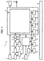
- FIG. 1 is a schematic view showing a digital camera according to the embodiment of the present invention.
- reference numeral 1 denotes a digital camera.
- the digital camera 1 includes a lens unit 2, an aperture stop shutter 3, an optical system driving unit 4, a range finding sensor 5, a CCD (charged-coupled device) 6, a CDS (correlated double sampling) circuit 7, an A/D converter 8, an image processing IC 9 as an aperture processing device and a digital filter processing device, a timing generator 10, a CPU 11, a memory for programming 12, a power source unit 13, a LCD 14, an external monitor connection jack 15, an image data recording unit 16, an operation unit 17, a strobe unit 18, and an image data buffer memory 19.
- a digital camera includes a lens unit 2, an aperture stop shutter 3, an optical system driving unit 4, a range finding sensor 5, a CCD (charged-coupled device) 6, a CDS (correlated double sampling) circuit 7, an A/D converter 8, an image processing IC 9 as an aperture processing device and a digital filter processing device, a timing generator 10,
- the lens unit 2 includes a focus lens and the like (not shown).
- the optical system driving unit 4 drives this lens unit 2, the aperture stop shutter 3 and so on, and sets up an appropriate optical condition when loading an image or monitoring.
- the optical system driving unit 4 drives the focus lens when automatic focusing is conducted by the after-mentioned CCD-AF system.
- the optical driving unit 4 includes a pulse motor (not shown) and a focus driver (not shown), and the focus driver drives the pulse motor in accordance with the control signal from the CPU11, and moves the focus lens along an optical axis.
- the range finding sensor 5 measures the distance to an object by a passive system, for example.
- the range finding sensor 5 has two lenses (not shown) arranged parallel rightward and leftward and two photo sensor arrays (not shown) arranged parallel rightward and leftward corresponding to these two lenses, respectively.
- quantity of light of an object image of each photo sensor array entered through the right and left lenses of the range finding sensor 5 is integrated by the range finding information arithmetic unit (not shown) of the image processing IC 9, and the disagreement of data obtained by the right and left photo sensor arrays is thereby calculated. Consequently, the range finding information arithmetic unit calculates the distance (object distance) to an object, and then outputs the calculated distance to the CPU 11.
- the range finding may be carried out by an active system with using the range finding sensor 5.
- the case for detecting the focal position by using the range finding sensor 5 is called the range finding sensor system (a second focusing system), and the case for detecting the focal position by using the CCD6 is called the CCD-AF system (a first focusing system).
- the CCD-AF system there is adopted a hill-climbing servo system in which the contrasts of object (AF evaluation value) corresponding to the image signals output from the CCD 6 are sampled with moving the focus lens, and the peak position of the AF evaluation value is considered as an focusing position.
- HBAF hybrid AF
- the digital camera 1 is capable of conducting both the automatic focusing processing by the HBAF system and the automatic focusing processing by the range finding sensor system, and it is adopted that a user can select either the automatic focusing processing by the HBAF system or the automatic focusing processing by the range fining sensor system by using the after-described automatic focusing key.
- the CCD 6 converts an image input through the lens unit 2 into an electronic. signal (analogue image data).
- the CDS circuit 7 is for reducing noise with respect to the CCD type image pick-up device.
- the A/D converter 8 converts the analogue image data from the CCD 6 into digital image data.
- the output signal of the CCD 6 is converted into a digital signal by an appropriate sampling frequency (for example, an integral multiple of sub carrier frequency of NTSC signal) thought the CDS circuit 7 and the A/D converter 8. This digital signal is sent to the after-described image processing IC 9.
- the timing generator 10 is for generating varied timing pulses to perform exposure time control and driving of the CCD 6.
- the CPU 11 controls the various operations of the digital camera 1 in accordance with the instruction from a user which passed the after-mentioned operation unit 17 and so on in accordance with a program stored in the memory 12 for programming. Particularly, the CPU 11 conducts the controls such as a photographing operation, an automatic exposure (AE) operation, an automatic white balance (AWB) adjusting operation, and an AF operation-
- a camera power source supplies a power to the various parts of the digital camera 1 such as the CPU 11 from the power source unit 13 such as NiCd, nickel hydride battery, or lithium battery.
- the LCD 14 displays digital image data obtained by photographing, image data obtained by expansion processing of recording data of the image data recording unit 16 and so on.
- the digital camera 1 can display the image data on an external monitor (not shown) by connecting the external monitor such as TV to an external monitor connection jack 15.
- the image data recording unit 16 is a PC card or the like which is connected detachably to a PC card interface, for example.
- the image data obtained by photographing an object is stored in the image data recording unit 16.
- the operation unit 17 is used by a user to carry out a functional selection, a photographing instruction, and various setups, and is constructed by a button and so on.
- the operation unit 17 includes a release key (not shown) for instructing photography, a zoom key (not shown) for setting up a zooming position (tale to wide), an automatic focusing key (not shown) for setting up the automatic focusing system (the HBAF system or the range finding sensor system) and so on.
- the CPU 11 carries out the automatic focusing operation when the release key is half pressed, and when the release key is full pressed, the CPU 11 performs the photographing operation.
- the strobe unit 18 emits light by the instruction of a user or automatically when photographing.
- the image processing IC 9 includes an image processing unit 20, a system control unit 21, an image compression unit 22, a scaling processing unit 23, and a memory control unit 24.
- the digital image data are input from the A/D converter 8 (inputting processing (S1)) through the image data buffer memory 19 such as SRAM, and this digital image data are separated into each color component of R, G, and B (R, G, and B separation processing (S2)).
- the WB evaluation value is obtained, and after each image data of R, G, and B are amplified by a predetermined magnification with digital processing (WB processing (S3)), ⁇ conversion of each image data of R, G, and B is conducted ( ⁇ processing (S4)), and each image data of R, G, and B is separated into color-difference signals (Cr, Cb) and a luminance signal (Y) (Y, C processing (S5)).
- Color signal processing (S6) such as adjusting a color phase or a saturation is conducted for the color-difference signals (Cr, Cb), while the after-mentioned edge enhancement processing (S7) and digital filter processing (S8) are carried out for the luminance signal (Y), and then these are synthesized and are output (output processing (S9)).
- the integrated value of the luminance signal in which the edge enhancement processing (S7) and the digital filter processing (S8) are conducted is obtained as the AF evaluation value (AF evaluation value obtaining processing (S10)), and is output to the CPU 11.
- the system control unit 21 performs controls of the whole image processing, and includes the after-mentioned two kinds of level conversion characteristics used in the edge enhancement processing (S7), and then sends the control signal to the after mentioned aperture control circuit 27 (reference to FIG. 3) based on these level conversion characteristics.
- the image compression unit 22 carries out wavelet transform conversion and inverse wavelet transform conversion, which is a process to the image compression and expansion conform to JPEG, and also carries out Huffman cording and decording which is a process to the process of the image compression and expansion conform to JPEG, for example.
- the scaling processing unit 23 adjusts, for example, the image size for the display size of LCD 14. For example, image data is recorded in the image data recording unit 16 by the memory control unit 24, and the memory control unit 24 conducts the control when reading the image data from the image data recording unit 16.
- FIG. 3 shows a circuit for carrying out the edge enhancement processing (S7).
- the circuit comprises a HPF (high pass filter) 28, delay circuits 29 and 30, a multiplier 31, a compositor 32, the aperture control circuit 27, and a compositor 33.
- HPF high pass filter
- the luminance signal (Y) is input in the HPF 28, and the high frequency component of the luminance signal is extracted in the HPF 28.
- the extracted high frequency luminance signal is input in the delay circuit 29 and the compositor 32.
- the delay output of the delay circuit 29 is input in the delay circuit 30, while the delay output is input in the multiplier 31 which conducts three times calculation to the input signal.
- the compositor 32 subtracts the original Y signal and the Y signal which is the delay output of the delay circuit 30 from the Y signal through the multiplier 31 from the delay circuit 29. The output from this compositor 32 becomes the edge component of the luminance signal.
- the edge component output from the compositor 32 is input in the aperture control circuit 27, and the aperture processing and coring processing are conducted based on the level conversion characteristics which are installed in advance and are included by the system control unit 21.
- a gain control signal as a control signal which is supplied from the system control unit 21 is provided, and the edge component of the luminance signal is enhanced by multiplying a predetermined gain (aperture gain) coefficient to the edge component of the luminance signal.
- the noise component contained in the edge component is eliminated by eliminating the component within the preinstalled coring range (coring) in the edge component from the compositor 32.
- FIG. 4 shows graphs indicating the level conversion characteristics in which the system control unit 21 includes;
- FIG. 4 A is a graph for standard edge processing used for the HBAF system;
- FIG. 4B is a graph for enhanced edge processing used for the range finding sensor system.
- a vertical axis shows a level of edge component input in the aperture control circuit 27, and a horizontal axis shows a level of edge component output from the aperture control circuit 27.
- the aperture gain Gb applied to the range finding sensor system is larger than the aperture gain Ga applied to the HBAF system, and the aperture limit Lb applied to the range finding sensor system is larger than the aperture limit La applied to the HBAF system.
- the coring Ca applied to the HBAF system and the coring Cb applied to the range finding sensor system are the same.
- the system control unit 21 receives information which of the automatic focusing system is selected by the automatic focusing key, from the CPU 11, and sends the control signal in accordance with the level conversion characteristic corresponding to the aperture control circuit 27 based on this information.
- the aperture control circuit 27 outputs the edge component of luminance signal to the compositor 33 after conducting the aperture processing and the coring processing.
- the edge component of the original picture signal is enhanced by superimposing the edge component from the aperture control circuit 27 to the luminance signal of the original picture signal (synthesizing by'the compositor 33).
- the digital filter processing (S8) is conducted for the luminance signal of the picture signal output from the compositor 33 by the above described high pass filter (HPF) (not shown).
- This high pass filter includes two kinds of filter coefficients for the enhanced edge processing shown in FIG. 5B and for the standard edge processing shown in FIG. 5A, and applies different filter coefficients based on the information which of automatic focusing system is selected by the automatic focusing key. More specifically, when the HBAF system is selected, the filter coefficients for the standard edge processing shown in FIG. 5A are applied to the high pass filter, and when the range finding sensor system is selected, the filter coefficients for the enhanced edge processing shown in FIG. 5B are applied, and then the digital filter processing (S8) is respectively carried out.
- the aperture gain Gb applied to the range finding sensor system is adopted to be larger than the aperture gain Ga applied to the HBAF system, so the low resolution by the automatic focusing can be compensated by enhancing the edge component of the picture signal. Therefore, the edge portion is enhanced in an image, and the resolution of apparent photographed image is improved.
- the aperture limit Lb applied to the range finding sensor system is adopted to be larger than the aperture limit La applied to the HBAF system.
- the edge component of the picture signal is thereby enhanced, and the edge portion is enhanced in an image and the resolution of apparent photographed image is improved.
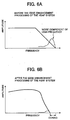
- FIG. 6 shows views indicating frame formats of changes in frequency characteristics of luminance signals obtained by the edge enhancement processing (aperture processing and coring processing) )(S7);
- FIG. 6A shows the frequency characteristic before the edge enhancement processing of the HBAF system;
- FIG. 6B shows the frequency characteristic after edge enhancement processing of the HBAF system;
- FIG. 6C shows the frequency characteristic before the edge enhancement processing of the range finding sensor;
- FIG. 6D shows the frequency characteristic after the edge enhancement processing of the range finding sensor.
- the vertical axis shows the frequency
- the horizontal axis shows the amplitude.
- the solid line shows the frequency distribution, and dotted line shows the noise component generated in a hard wear such as the CCD 6.
- the HBAF system has high focusing accuracy, so the frequency characteristic before the edge enhancement processing is distributed up to the high frequency as shown in FIG. 6 A.
- the edge enhancement processing is applied to the HBAF system, as shown in FIG. 6B, the high frequency area which tends to be dominated by noise is cut by the coring processing, and an ideal frequency distribution can be obtained by the aperture processing.
- the focusing accuracy of the range finding system is interior to that of the HBAF system, as shown in FIG. 6C, so the frequency characteristic before the edge enhancement processing (S7) is not extended to the high frequency compared to FIG. 6A. Therefore the resolution is decreased.
- the edge enhancement processing (S7) is applied to the range finding system, as shown in FIG. 6D, the frequency characteristic of the high frequency area is increased, and the edge portion is enhanced in an image, and the resolution of apparent photographed image is improved.
- the high frequency component is further enhanced than the filter coefficients applied to the HBAF system, so the high frequency component of the picture signal is thereby enhanced, and the edge portion is enhanced in an image, and then the resolution of apparent photographed image is improved. Therefore, by using the range finding sensor system, the resolution of photographed image can be improved with shortening the release time-lag.
- the aperture gain can he changed, but it is different from the present invention in that the aperture gain is respectively set up based on the optical condition such as a zooming position or an aperture stop diameter of camera.
- the digital filter characteristic and coring are changed by a photographing mode, but in the present invention, the digital filter characteristics and the like are changed by the automatic focusing system, and the coring stays constant.
- the present invention is not limited to the above described embodiment.
- the aperture gain and the aperture limit are adopted to be larger than when the HBAF system is used, and the filter coefficients arc characterized to further enhance the high frequency component; however, all of these conditions are not always required. It is possible to use only one condition, and it is also possible to combine appropriate conditions.
- a user can select either the HBAF system or the range finding sensor system by use of the automatic focusing key, but the automatic focusing system can be selected automatically depending on, for example, a photographing condition and the like.
- either HBAF system or the range finding sensor system is adopted to select; however the automatic focusing system can be selected from either CCD-AF system or the range finding sensor system, for example, and also it can be selected from any one of systems such as the CCD-AF system, the HBAF system, and the range finding sensor system. Moreover, it can be selected from either the CCD-AF system or HBAF system.
- the image processing unit 20 it is adopted to obtain the WB evaluation value after separating into each color component of R, G, and B, but it can be obtained after conducting the ⁇ conversion, for example. Furthermore, the AF evaluation value is adopted to obtain after the digital filter processing (S8), but it can be conducted before the digital filter processing.
- the present invention is constructed as described above; therefore, the present invention makes it possible to improve the resolution of photographed image by using the range finding sensor system with shortening the release time-lag.
Landscapes
- Engineering & Computer Science (AREA)
- Multimedia (AREA)
- Signal Processing (AREA)
- Studio Devices (AREA)
- Automatic Focus Adjustment (AREA)
- Focusing (AREA)
- Measurement Of Optical Distance (AREA)
Abstract
Description
Claims (3)
- A digital camera 1 comprising:characterized in thata first focusing system for obtaining a focusing position by sampling a contrast of an object image formed on a light receiving surface whilst moving a focus lens along an optical axis;a second focusing system for obtaining a focusing position by measuring a distance to an object based on a triangular surveying system; andan aperture processing device to correct an edge component of an image signal of a photographed image obtained by photographing said object,
when said second focusing system is used independently, said aperture processing device enhances said edge component by using a larger aperture gain Gb than when said first focusing system is used independently or when said first focusing system and said second focusing system are used together. - A digital camera 1 comprising:characterized in thata first focusing system for obtaining a focusing position by sampling a contrast of an object image formed on a light receiving surface whilst moving a focus lens along an optical axis;a second focusing system for obtaining the focusing position by measuring a distance to an object based on a triangular surveying system; andan aperture processing device to correct an edge component of an image signal of a photographed image obtained by photographing said object,
when said second focusing system is used independently, said aperture processing device enhances said edge component by using a larger aperture limit Lb than when said first focusing system is used independently or when said first focusing system and said second focusing system are used together. - A digital camera 1 comprising:characterized in thata first focusing system for obtaining a focusing position by sampling a contrast of an obiect image formed on a light receiving surface whilst moving a focus lens along an optical axis;a second focusing system for obtaining the focusing position by measuring a distance to an object based on a triangular surveying system; anda digital filter processing device to correct a high frequency component of an image signal of a photographed image obtained by photographing said object,
when said second focusing system is used independently, said digital filter processing device uses a filter coefficient having a characteristic of further enhancing said high frequency component than when said first focusing system is used independently or said first focusing system and said second focusing system are used together.
Applications Claiming Priority (2)
| Application Number | Priority Date | Filing Date | Title |
|---|---|---|---|
| JP2002350749A JP3964315B2 (en) | 2002-12-03 | 2002-12-03 | Digital camera |
| JP2002350749 | 2002-12-03 |
Publications (3)
| Publication Number | Publication Date |
|---|---|
| EP1434427A2 true EP1434427A2 (en) | 2004-06-30 |
| EP1434427A3 EP1434427A3 (en) | 2008-01-02 |
| EP1434427B1 EP1434427B1 (en) | 2011-10-19 |
Family
ID=32463117
Family Applications (1)
| Application Number | Title | Priority Date | Filing Date |
|---|---|---|---|
| EP03257602A Expired - Lifetime EP1434427B1 (en) | 2002-12-03 | 2003-12-03 | Digital camera |
Country Status (3)
| Country | Link |
|---|---|
| US (1) | US20040169766A1 (en) |
| EP (1) | EP1434427B1 (en) |
| JP (1) | JP3964315B2 (en) |
Cited By (1)
| Publication number | Priority date | Publication date | Assignee | Title |
|---|---|---|---|---|
| WO2008016566A3 (en) * | 2006-08-01 | 2008-03-27 | Eastman Kodak Co | Focus system calibration for image capture systems |
Families Citing this family (11)
| Publication number | Priority date | Publication date | Assignee | Title |
|---|---|---|---|---|
| TWI250793B (en) * | 2004-12-15 | 2006-03-01 | Asia Optical Co Inc | Range-finding type digital camera |
| JP2007274669A (en) * | 2006-03-10 | 2007-10-18 | Ricoh Co Ltd | Imaging device |
| JP2008079123A (en) * | 2006-09-22 | 2008-04-03 | Olympus Corp | Imaging apparatus and focus control program |
| JP4954659B2 (en) * | 2006-10-10 | 2012-06-20 | 株式会社リコー | Imaging device |
| US7813633B2 (en) * | 2007-07-31 | 2010-10-12 | Ricoh Company, Ltd. | Imaging device and imaging method |
| JP5381060B2 (en) * | 2008-02-05 | 2014-01-08 | 株式会社リコー | Imaging apparatus and image processing method thereof |
| JP5206494B2 (en) | 2009-02-27 | 2013-06-12 | 株式会社リコー | Imaging device, image display device, imaging method, image display method, and focus area frame position correction method |
| JP5553199B2 (en) * | 2009-11-10 | 2014-07-16 | 株式会社リコー | Imaging apparatus and imaging control method |
| JP2013013050A (en) * | 2011-05-27 | 2013-01-17 | Ricoh Co Ltd | Imaging apparatus and display method using imaging apparatus |
| JP5978620B2 (en) | 2011-12-21 | 2016-08-24 | 株式会社リコー | Imaging device |
| KR102585233B1 (en) * | 2018-06-15 | 2023-10-05 | 삼성전자주식회사 | Display apparatus and method of manufacturing display apparatus |
Family Cites Families (19)
| Publication number | Priority date | Publication date | Assignee | Title |
|---|---|---|---|---|
| JPS5396828A (en) * | 1977-02-03 | 1978-08-24 | Bell & Howell Japan | Automatic focal point adjusting device |
| US4975726A (en) * | 1987-11-25 | 1990-12-04 | Matsushita Electric Industrial Co., Ltd. | Automatic focusing apparatus |
| DE69232455T2 (en) * | 1991-08-21 | 2002-06-27 | Canon K.K., Tokio/Tokyo | Video camera with a variety of photographic modes |
| US5694168A (en) * | 1991-09-04 | 1997-12-02 | Fuji Photo Film Co., Ltd. | Auto focus control device and method including selecting a zone for detecting an evaluative value for focusing in accordance with photographing direction |
| JPH06205269A (en) * | 1993-01-06 | 1994-07-22 | Matsushita Electric Ind Co Ltd | Autofocus device and video camera |
| US5838371A (en) * | 1993-03-05 | 1998-11-17 | Canon Kabushiki Kaisha | Image pickup apparatus with interpolation and edge enhancement of pickup signal varying with zoom magnification |
| JPH0743605A (en) * | 1993-08-02 | 1995-02-14 | Minolta Co Ltd | Automatic focusing device |
| JP3150243B2 (en) * | 1993-10-25 | 2001-03-26 | キヤノン株式会社 | Distance measuring device and camera |
| US5696850A (en) * | 1995-12-21 | 1997-12-09 | Eastman Kodak Company | Automatic image sharpening in an electronic imaging system |
| JPH0990204A (en) * | 1996-03-25 | 1997-04-04 | Minolta Co Ltd | Automatic focusing device |
| JPH1123955A (en) * | 1997-07-08 | 1999-01-29 | Nikon Corp | Auto focus camera |
| NZ332626A (en) * | 1997-11-21 | 2000-04-28 | Matsushita Electric Industrial Co Ltd | Expansion of dynamic range for video camera |
| US6614474B1 (en) * | 1998-08-27 | 2003-09-02 | Polycom, Inc. | Electronic pan tilt zoom video camera with adaptive edge sharpening filter |
| JP2001141986A (en) * | 1999-11-16 | 2001-05-25 | Olympus Optical Co Ltd | Electronic camera and automatic focusing device for electronic camera |
| JP2001223941A (en) * | 1999-12-01 | 2001-08-17 | Ricoh Co Ltd | Imaging device and imaging method |
| US6453124B2 (en) * | 2000-03-27 | 2002-09-17 | Minolta Co., Ltd. | Digital camera |
| US6533721B1 (en) * | 2001-07-27 | 2003-03-18 | Stryker Corporation | Endoscopic camera system with automatic non-mechanical focus |
| JP3863808B2 (en) * | 2002-05-27 | 2006-12-27 | 三洋電機株式会社 | Outline enhancement circuit |
| US6895181B2 (en) * | 2002-08-27 | 2005-05-17 | Olympus Corporation | Camera and distance measuring method thereof |
-
2002
- 2002-12-03 JP JP2002350749A patent/JP3964315B2/en not_active Expired - Fee Related
-
2003
- 2003-12-03 EP EP03257602A patent/EP1434427B1/en not_active Expired - Lifetime
- 2003-12-03 US US10/725,401 patent/US20040169766A1/en not_active Abandoned
Cited By (4)
| Publication number | Priority date | Publication date | Assignee | Title |
|---|---|---|---|---|
| WO2008016566A3 (en) * | 2006-08-01 | 2008-03-27 | Eastman Kodak Co | Focus system calibration for image capture systems |
| EP2047673A2 (en) * | 2006-08-01 | 2009-04-15 | Eastman Kodak Company | Focus system calibration for image capture systems |
| US7609958B2 (en) | 2006-08-01 | 2009-10-27 | Eastman Kodak Company | Automatic focus system calibration for image capture systems |
| US8416317B2 (en) | 2006-08-01 | 2013-04-09 | Apple Inc. | Automatic focus system calibration for image capture systems |
Also Published As
| Publication number | Publication date |
|---|---|
| EP1434427A3 (en) | 2008-01-02 |
| EP1434427B1 (en) | 2011-10-19 |
| JP3964315B2 (en) | 2007-08-22 |
| JP2004186933A (en) | 2004-07-02 |
| US20040169766A1 (en) | 2004-09-02 |
Similar Documents
| Publication | Publication Date | Title |
|---|---|---|
| KR101278241B1 (en) | Photographing apparatus and photographing method | |
| US7706674B2 (en) | Device and method for controlling flash | |
| US7663688B2 (en) | Image capture apparatus and focus adjustment method | |
| JP4127491B2 (en) | Camera with auto focus function | |
| TWI422219B (en) | Photography device and photography method, and computer readable recording medium | |
| US8988579B2 (en) | Imaging apparatus | |
| US20110122268A1 (en) | Imaging device | |
| JP4543602B2 (en) | camera | |
| CN108462830A (en) | The control method of photographic device and photographic device | |
| EP1434427B1 (en) | Digital camera | |
| JP2012217100A (en) | Imaging device and imaging device control method and program | |
| JP4614143B2 (en) | Imaging apparatus and program thereof | |
| US7317488B2 (en) | Method of and system for autofocus | |
| JP2011013645A (en) | Imaging device | |
| CN110121024A (en) | Device for image stabilization, camera system and its control method | |
| JP3820076B2 (en) | Automatic focusing device, digital camera, portable information input device, focusing position detection method, and computer-readable recording medium | |
| US7925149B2 (en) | Photographing apparatus and method for fast photographing capability | |
| US20010055064A1 (en) | Digital still camera | |
| JP5532621B2 (en) | Electronic camera and image processing program | |
| JP2005026888A (en) | Digital camera with camera shake display function | |
| JP5013852B2 (en) | Angle of view correction apparatus and method, and imaging apparatus | |
| JP4046276B2 (en) | Digital camera | |
| KR20120070489A (en) | Image taking device and method | |
| US7372504B2 (en) | Camera with video capturing button and still capturing button capable of simultaneous operation | |
| JP2007057974A (en) | Imaging device |
Legal Events
| Date | Code | Title | Description |
|---|---|---|---|
| PUAI | Public reference made under article 153(3) epc to a published international application that has entered the european phase |
Free format text: ORIGINAL CODE: 0009012 |
|
| 17P | Request for examination filed |
Effective date: 20031212 |
|
| AK | Designated contracting states |
Kind code of ref document: A2 Designated state(s): AT BE BG CH CY CZ DE DK EE ES FI FR GB GR HU IE IT LI LU MC NL PT RO SE SI SK TR |
|
| AX | Request for extension of the european patent |
Extension state: AL LT LV MK |
|
| RAP1 | Party data changed (applicant data changed or rights of an application transferred) |
Owner name: RICOH COMPANY, LTD. |
|
| PUAL | Search report despatched |
Free format text: ORIGINAL CODE: 0009013 |
|
| AK | Designated contracting states |
Kind code of ref document: A3 Designated state(s): AT BE BG CH CY CZ DE DK EE ES FI FR GB GR HU IE IT LI LU MC NL PT RO SE SI SK TR |
|
| AX | Request for extension of the european patent |
Extension state: AL LT LV MK |
|
| AKX | Designation fees paid |
Designated state(s): DE ES FR GB IT NL |
|
| 17Q | First examination report despatched |
Effective date: 20100517 |
|
| GRAP | Despatch of communication of intention to grant a patent |
Free format text: ORIGINAL CODE: EPIDOSNIGR1 |
|
| GRAS | Grant fee paid |
Free format text: ORIGINAL CODE: EPIDOSNIGR3 |
|
| GRAA | (expected) grant |
Free format text: ORIGINAL CODE: 0009210 |
|
| AK | Designated contracting states |
Kind code of ref document: B1 Designated state(s): DE ES FR GB IT NL |
|
| REG | Reference to a national code |
Ref country code: GB Ref legal event code: FG4D |
|
| REG | Reference to a national code |
Ref country code: DE Ref legal event code: R096 Ref document number: 60338803 Country of ref document: DE Effective date: 20111215 |
|
| REG | Reference to a national code |
Ref country code: NL Ref legal event code: VDEP Effective date: 20111019 |
|
| PG25 | Lapsed in a contracting state [announced via postgrant information from national office to epo] |
Ref country code: NL Free format text: LAPSE BECAUSE OF FAILURE TO SUBMIT A TRANSLATION OF THE DESCRIPTION OR TO PAY THE FEE WITHIN THE PRESCRIBED TIME-LIMIT Effective date: 20111019 |
|
| PLBE | No opposition filed within time limit |
Free format text: ORIGINAL CODE: 0009261 |
|
| STAA | Information on the status of an ep patent application or granted ep patent |
Free format text: STATUS: NO OPPOSITION FILED WITHIN TIME LIMIT |
|
| PG25 | Lapsed in a contracting state [announced via postgrant information from national office to epo] |
Ref country code: IT Free format text: LAPSE BECAUSE OF FAILURE TO SUBMIT A TRANSLATION OF THE DESCRIPTION OR TO PAY THE FEE WITHIN THE PRESCRIBED TIME-LIMIT Effective date: 20111019 |
|
| 26N | No opposition filed |
Effective date: 20120720 |
|
| REG | Reference to a national code |
Ref country code: DE Ref legal event code: R097 Ref document number: 60338803 Country of ref document: DE Effective date: 20120720 |
|
| PG25 | Lapsed in a contracting state [announced via postgrant information from national office to epo] |
Ref country code: ES Free format text: LAPSE BECAUSE OF FAILURE TO SUBMIT A TRANSLATION OF THE DESCRIPTION OR TO PAY THE FEE WITHIN THE PRESCRIBED TIME-LIMIT Effective date: 20120130 |
|
| REG | Reference to a national code |
Ref country code: FR Ref legal event code: PLFP Year of fee payment: 13 |
|
| REG | Reference to a national code |
Ref country code: FR Ref legal event code: PLFP Year of fee payment: 14 |
|
| PGFP | Annual fee paid to national office [announced via postgrant information from national office to epo] |
Ref country code: GB Payment date: 20161222 Year of fee payment: 14 Ref country code: DE Payment date: 20161213 Year of fee payment: 14 |
|
| PGFP | Annual fee paid to national office [announced via postgrant information from national office to epo] |
Ref country code: FR Payment date: 20161222 Year of fee payment: 14 |
|
| REG | Reference to a national code |
Ref country code: DE Ref legal event code: R119 Ref document number: 60338803 Country of ref document: DE |
|
| GBPC | Gb: european patent ceased through non-payment of renewal fee |
Effective date: 20171203 |
|
| REG | Reference to a national code |
Ref country code: FR Ref legal event code: ST Effective date: 20180831 |
|
| PG25 | Lapsed in a contracting state [announced via postgrant information from national office to epo] |
Ref country code: DE Free format text: LAPSE BECAUSE OF NON-PAYMENT OF DUE FEES Effective date: 20180703 Ref country code: FR Free format text: LAPSE BECAUSE OF NON-PAYMENT OF DUE FEES Effective date: 20180102 |
|
| PG25 | Lapsed in a contracting state [announced via postgrant information from national office to epo] |
Ref country code: GB Free format text: LAPSE BECAUSE OF NON-PAYMENT OF DUE FEES Effective date: 20171203 |