EP1434357A2 - Power saving method for an electronic device - Google Patents
Power saving method for an electronic device Download PDFInfo
- Publication number
- EP1434357A2 EP1434357A2 EP03027805A EP03027805A EP1434357A2 EP 1434357 A2 EP1434357 A2 EP 1434357A2 EP 03027805 A EP03027805 A EP 03027805A EP 03027805 A EP03027805 A EP 03027805A EP 1434357 A2 EP1434357 A2 EP 1434357A2
- Authority
- EP
- European Patent Office
- Prior art keywords
- electronic device
- information
- transmission source
- wakeup request
- wakeup
- Prior art date
- Legal status (The legal status is an assumption and is not a legal conclusion. Google has not performed a legal analysis and makes no representation as to the accuracy of the status listed.)
- Withdrawn
Links
Images


Classifications
-
- H—ELECTRICITY
- H04—ELECTRIC COMMUNICATION TECHNIQUE
- H04W—WIRELESS COMMUNICATION NETWORKS
- H04W52/00—Power management, e.g. Transmission Power Control [TPC] or power classes
- H04W52/02—Power saving arrangements
- H04W52/0209—Power saving arrangements in terminal devices
- H04W52/0225—Power saving arrangements in terminal devices using monitoring of external events, e.g. the presence of a signal
- H04W52/0229—Power saving arrangements in terminal devices using monitoring of external events, e.g. the presence of a signal where the received signal is a wanted signal
-
- G—PHYSICS
- G06—COMPUTING OR CALCULATING; COUNTING
- G06F—ELECTRIC DIGITAL DATA PROCESSING
- G06F1/00—Details not covered by groups G06F3/00 - G06F13/00 and G06F21/00
- G06F1/26—Power supply means, e.g. regulation thereof
- G06F1/32—Means for saving power
- G06F1/3203—Power management, i.e. event-based initiation of a power-saving mode
-
- H—ELECTRICITY
- H04—ELECTRIC COMMUNICATION TECHNIQUE
- H04L—TRANSMISSION OF DIGITAL INFORMATION, e.g. TELEGRAPHIC COMMUNICATION
- H04L12/00—Data switching networks
- H04L12/02—Details
- H04L12/12—Arrangements for remote connection or disconnection of substations or of equipment thereof
-
- Y—GENERAL TAGGING OF NEW TECHNOLOGICAL DEVELOPMENTS; GENERAL TAGGING OF CROSS-SECTIONAL TECHNOLOGIES SPANNING OVER SEVERAL SECTIONS OF THE IPC; TECHNICAL SUBJECTS COVERED BY FORMER USPC CROSS-REFERENCE ART COLLECTIONS [XRACs] AND DIGESTS
- Y02—TECHNOLOGIES OR APPLICATIONS FOR MITIGATION OR ADAPTATION AGAINST CLIMATE CHANGE
- Y02D—CLIMATE CHANGE MITIGATION TECHNOLOGIES IN INFORMATION AND COMMUNICATION TECHNOLOGIES [ICT], I.E. INFORMATION AND COMMUNICATION TECHNOLOGIES AIMING AT THE REDUCTION OF THEIR OWN ENERGY USE
- Y02D30/00—Reducing energy consumption in communication networks
- Y02D30/70—Reducing energy consumption in communication networks in wireless communication networks
Definitions
- the present invention relates to an electronic device and a power control method in the electronic device and, more particularly, to a wireless communication apparatus which can resume operations from a suspended state in response to a wakeup request from another apparatus, and a power control method therefor.
- an electronic device comprising means for receiving a wakeup request for the electronic device in a suspended state, and a frame containing information representing a transmission source device, and means for determining wakeup of the electronic device on the basis of the transmission source information contained in the received frame.
- a power control method in an electronic device which further comprises steps of outputting an inquiry signal, collecting frames which are transmitted in response to the inquiry signal and contain pieces of information representing a plurality of transmission source devices, registering, as first information in a table, information representing a predetermined type of device out of the pieces of information which are contained in the collected frames and represent the transmission source devices, and registering, in the table in association with the first information, second information representing that connection has been established for the predetermined type of device represented by the first information, and in which the decision is made by looking up the table.
- FIG. 1 is a block diagram showing the arrangement of the wireless communication apparatus according to the embodiment of the present invention.
- a communication terminal 1 and wireless module 2 are connected via a USB (Universal Serial Bus).
- the communication terminal 1 wirelessly communicates with a wireless input device 3 such as a keyboard or mouse via the wireless module 2.
- reference numeral 4 denotes an application program which runs on an OS (Operating System) 9, and if necessary, outputs a suspend request or wakeup request.
- OS Operating System
- a Bluetooth protocol stack 5 is a group of Bluetooth protocol drivers.
- An HCI (Host Control Interface) 6 is an interface which executes processing in accordance with a Bluetooth protocol request.
- a USB driver 7 controls a USB interface 8.
- the OS 9 is the OS of the communication terminal 1, and the application program 4 is executed on the OS 9.
- a power controller 10 controls the power of the communication terminal 1, controls the power of the wireless module 2, and performs processing shown in FIG. 3.
- a USB driver 12 controls a USB interface 11.
- An HCI 13 manages a link manager 14 of the wireless module 2.
- the link manager 14 is a protocol for establishing Bluetooth communication, and instructs a link controller (baseband layer) 15 to set a communication link and various communication parameters regarding the link.
- the link controller 15 is a Bluetooth baseband, and is a protocol which interfaces actual transmission/reception data packets with a physical layer.
- An RF 16 is a wireless communication I/F(interface) which modulates/demodulates a signal input/output to/from an antenna and outputs the resultant signal to the antenna or the link controller 15 serving as a baseband.
- An HID (Human Interface Device) packet recognition unit 17 realizes processing according to the embodiment of the present invention.
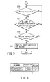
- the HID packet recognition unit 17 performs processes shown in FIGS. 4 and 5, and saves and manages a table shown in FIG. 6.
- Reference numeral 18 denotes data input from the input device such as a keyboard or mouse.
- An HCI 19 manages a link manager 20 of the input device 3.
- the link manager 20 is a protocol for establishing Bluetooth communication, and instructs a link controller (baseband layer) 21 to set a communication link and various communication parameters regarding the link.
- the link controller 21 is a Bluetooth baseband, and is a protocol which interfaces actual transmission/reception data packets with a physical layer.
- An RF 22 is a wireless communication I/F which modulates/demodulates a signal input/output to/from an antenna and outputs the resultant signal to the antenna or the link controller 21 serving as a baseband.
- FIG. 2 is a view showing the state transition of the communication terminal.
- the communication terminal 1 Before power-on, the communication terminal 1 is in state A. That is, the Bluetooth function is OFF, and the USB is electronically disconnected or disabled.
- the power controller 10 powers on the wireless module 2, connects the USB 8, and changes to state B. In state B, the Bluetooth function is ON, and the USB is attached.
- the communication terminal 1 suspends operation in a power-saving mode in response to an instruction from the user or the OS 9, the communication terminal 1 changes to state C, and notifies the HID packet recognition unit 17 of a message to that effect.
- state C the Bluetooth function is ON, and the USB is disconnected or disabled.
- the communication terminal 1 waits for a wakeup request from the HID packet recognition unit 17.
- the HID packet recognition unit 17 recognizes a packet transmitted from the wireless input device 3, and notifies the power controller 10 of the wakeup request.
- the power controller 10 resumes operation of the communication terminal 1 in response to notification of the wakeup request from the HID packet recognition unit 17.
- the communication terminal 1 then changes from state C to state B. If the OS 9 or the like designates power-off, the communication terminal 1 changes from state B to state A.
- the power controller 10 designates a power-on operation of the wireless module 2 (S2), establishes connection to the wireless input device 3 (S3), and performs communication with the wireless input device (S4).
- the power controller 10 determines whether the OS 9 or the like has output a suspend request for the communication terminal 1 (S5). If YES in S5, the power controller 10 performs a suspend processing operation (S6); if NO, operation continues processing in S4.
- the power controller 10 performs suspend processing and suspends operation of the communication terminal 1which corresponds to state B in FIG. 2.
- the power controller 10 determines whether it has received a wakeup notification from the HID packet recognition unit 17 (S7). If YES in S7, the power controller 10 resumes operation of the communication terminal 1 (S8).
- the power controller 10 receives a wakeup notification from the HID packet recognition unit 17 while the communication terminal 1 is in the suspended state, the power controller 10 resumes operation of the communication terminal 1.
- HID packet recognition unit 17 The operation of the HID packet recognition unit 17 will be explained with reference to the flow charts of FIGS. 4 and 5.
- the HID packet recognition unit 17 executes an inquiry in order to detect an HID (Human Interface Device) class device (S12).
- each device sends back an FHS (Frequency Hop Synchronization) packet.
- the wireless module 2 receives the FHS packet (S13), and each device extracts only HID class BD_ADDR (Bluetooth Device Address) from the received FHS packet and creates a table.
- FIG. 6 shows an example of the table. As shown in FIG. 6, this table stores BD_ADDR representing the address of a Bluetooth device, a connection handle, and an active flag representing whether connection has been established. In S14,the BD_ADDR is stored in the table of FIG. 6.
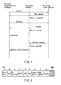
- FIG. 8 is a view showing an FHS payload format. Of an FHS packet field, only fields pertaining to the embodiments of the present invention will be described, and a description of the remaining fields will be omitted. Each field of the FHS packet is described in "Bluetooth specification”.
- an "LAP” field has 24'bits, and stores information at the lower address portion of a unit which transmits an FHS packet.
- a "UAP” field has eight bits, and stores information at the upper address portion of the unit which transmits an FHS packet. That is, BD_ADDR can be acquired by referring to the "LAP" field and "UAP” field.
- a device class (Class of device) field has 24 bits, and stores information representing the device class of the unit which transmits an FHS packet. That is, whether the device is an HID can be determined by referring to the device class field.
- the HID packet recognition unit 17 determines whether it has received a connection request from the OS 9 or the like (S15). If YES in S15, the HID packet recognition unit 17 performs connection processing and establishes a connection (S16) between the communication terminal 1 and the wireless input device of interest (e.g., device 3). The HID packet recognition unit 17 acquires a connection handle, stores it in the table, and manages the acquired connection handle to be active in the table (S17). As for an HID with which no connection is established, a connection handle is managed as inactive.
- the HID packet recognition unit 17 determines whether it has received a suspend request from the power controller (S18). If YES in S18, the HID packet recognition unit 17 performs suspend processing (S19) to suspend operation of the communication terminal 1 and wireless module 2.
- the HID packet recognition unit 17 determines whether it has received a wakeup request from the wireless input device 3 in the suspended state (S20 - FIG. 5). If YES in S20, the HID packet recognition unit 17 determines whether BD_ADDR of the transmission source device that is contained in the wakeup request has been registered in the table (S21). If NO in S21, the HID packet recognition unit 17 returns to processing in S20 to ignore the wakeup request.
- the HID packet recognition unit 17 determines whether an active flag corresponding to the BD_ADDR and connection handle of the device which has output the wakeup request is active (S22).
- the HID packet recognition unit 17 If NO in S22, the HID packet recognition unit 17 returns to processing in S20. That is, the HID packet recognition unit 17 ignores a wakeup request output from an HID class device which has been registered in the table but exhibits an "inactive" active flag.
- the HID packet recognition unit 17 notifies the power controller 10 of the wakeup request (S23), and ends processing. In response to this, the power controller 10 resumes operation of the communication terminal 1.
- the active flag serves as an indication to the HID packet recognition unit 17 of whether or not to wakeup or resume operation of the communication terminal 1 from the standby mode.
- the wakeup request is only honored from active wireless input devices (devices that are "connected” in step S16 of FIG. 4) which have been registered in the table (i.e., handle is stored in the table).
- FIG. 7 is a timing chart for explaining a data flow between the wireless communication terminal 1, the wireless module 2, and the wireless input device 3.
- the communication terminal 1 and wireless module 2 are connected via the USB in FIG. 1, but the wireless module 2 may be assembled in the communication terminal 1.
- a table representing a device which can issue a wakeup request is created in advance.
- whether or not wakeup is perform is determined by looking up the data in the table. Resumption of operations based on a wakeup request from an unspecified device can be prevented, and thus an increase in power consumption by unnecessary activation can be prevented.
Landscapes
- Engineering & Computer Science (AREA)
- Theoretical Computer Science (AREA)
- Computer Networks & Wireless Communication (AREA)
- Signal Processing (AREA)
- Physics & Mathematics (AREA)
- General Engineering & Computer Science (AREA)
- General Physics & Mathematics (AREA)
- Mobile Radio Communication Systems (AREA)
- Power Sources (AREA)
Abstract
Description
Claims (8)
- An electronic device characterized by comprising:means (10) for receiving a wakeup request for the electronic device in a suspended state, and a frame containing information representing a transmission source device as transmission source information; andmeans (10) for conditioning resumption of operation of the electronic device on the basis of the wakeup request and the transmission source information contained in the received frame.
- The device according to claim 1, which further comprises a table in which first information representing a predetermined type of device and second information representing whether to resume operation of the electronic device in response to the wakeup request from the device represented by the first information are stored in association with each other, and in which the conditioning means accesses said table and permits resumption of operation of the electronic device when the information representing the transmission source is registered as the first information in the table and the second information associated with the information representing the transmission source indicates resumption of operation is permitted in response to the wakeup request.
- The device according to claim 2, characterized in that the table registers only information representing a predetermined type of device as the first information, out of pieces of information which represent transmission source devices and are contained in frames that are collected in response to an inquiry signal and represent a plurality of transmission source devices.
- The device according to claim 2, characterized in that the second information permits a wakeup request from a device which has established connection to the electronic device to effect resumption of operations of the electronic device.
- The device according to claim 2, characterized in that the predetermined type of device includes a human interface device.
- The device according to claim 1, characterized in that the receiving means and the determining means are arranged in a wireless module.
- The device according to claim 1, characterized by further comprising means for resuming the electronic device when wakeup of the electronic device is determined.
- The device according to claim 1, characterized in that the electronic device includes a wireless communication device.
Applications Claiming Priority (2)
| Application Number | Priority Date | Filing Date | Title |
|---|---|---|---|
| JP2002377168A JP3813925B2 (en) | 2002-12-26 | 2002-12-26 | Electronic device and power supply control method in electronic device |
| JP2002377168 | 2002-12-26 |
Publications (2)
| Publication Number | Publication Date |
|---|---|
| EP1434357A2 true EP1434357A2 (en) | 2004-06-30 |
| EP1434357A3 EP1434357A3 (en) | 2005-10-26 |
Family
ID=32463584
Family Applications (1)
| Application Number | Title | Priority Date | Filing Date |
|---|---|---|---|
| EP03027805A Withdrawn EP1434357A3 (en) | 2002-12-26 | 2003-12-03 | Power saving method for an electronic device |
Country Status (4)
| Country | Link |
|---|---|
| US (1) | US20040132502A1 (en) |
| EP (1) | EP1434357A3 (en) |
| JP (1) | JP3813925B2 (en) |
| CN (1) | CN1512296A (en) |
Cited By (3)
| Publication number | Priority date | Publication date | Assignee | Title |
|---|---|---|---|---|
| GB2424526A (en) * | 2003-10-16 | 2006-09-27 | Nokia Corp | Power management in a device having a radio receiver section and a telcoms section |
| US7356319B2 (en) | 2003-10-16 | 2008-04-08 | Nokia Corporation | Reduced power consumption |
| EP1920801A2 (en) | 2006-11-09 | 2008-05-14 | Sony Computer Entertainment Inc. | Information communication system, information processing unit, and information communication method |
Families Citing this family (15)
| Publication number | Priority date | Publication date | Assignee | Title |
|---|---|---|---|---|
| JP2007312243A (en) * | 2006-05-19 | 2007-11-29 | Toshiba Corp | Terminal device, communication system, and terminal device activation method |
| US8170624B1 (en) * | 2006-11-10 | 2012-05-01 | Marvell International Ltd. | Enhanced host sleep for WLAN devices |
| CN101620463A (en) * | 2008-06-30 | 2010-01-06 | 株式会社东芝 | Information processing apparatus and wake-up control method |
| US8352764B2 (en) * | 2008-09-29 | 2013-01-08 | Intel Corporation | Dynamic squelch detection power control |
| CN101446911B (en) * | 2009-01-06 | 2010-09-29 | 中兴通讯股份有限公司 | A method and device for time-sharing processing |
| JP4714294B1 (en) | 2009-12-16 | 2011-06-29 | 株式会社東芝 | Communication apparatus and communication method |
| EP2532144B1 (en) * | 2010-02-06 | 2014-04-02 | ST-Ericsson SA | System and method for wireless stack implementation on multiple wireless devices |
| JP2011221910A (en) * | 2010-04-13 | 2011-11-04 | Toyota Motor Corp | Information processor corresponding to low power consumption and information processing system corresponding to low power consumption |
| KR20130051153A (en) * | 2011-11-09 | 2013-05-20 | 삼성전자주식회사 | Display apparatus and control method thereof |
| WO2013108134A2 (en) | 2012-01-18 | 2013-07-25 | Marvel World Trade Ltd. | Intelligent detection interface for wireless devices |
| CN102701077B (en) * | 2012-06-21 | 2014-12-31 | 三一重工股份有限公司 | System and method for controlling position of lifting hook of crane, as well as crane |
| EP2750325A3 (en) * | 2012-12-28 | 2016-05-11 | Ricoh Company, Ltd. | Communication apparatus, communication system, communication method, and recording medium storing communication control program |
| CN106658377B (en) * | 2016-12-26 | 2020-04-14 | 广州立功科技股份有限公司 | Bluetooth low energy communication method and device |
| KR102323176B1 (en) * | 2017-09-19 | 2021-11-08 | 엘지전자 주식회사 | Display device and terminal controlling the same |
| CN109981299B (en) * | 2019-03-05 | 2021-06-01 | 青岛海信传媒网络技术有限公司 | Wake-up method and device |
Family Cites Families (3)
| Publication number | Priority date | Publication date | Assignee | Title |
|---|---|---|---|---|
| US6618580B2 (en) * | 2000-02-14 | 2003-09-09 | Intel Corporation | Apparatus and method for remotely powering-down a wireless transceiver |
| JP2002268778A (en) * | 2001-03-14 | 2002-09-20 | Toshiba Corp | Information processing device |
| AUPR405601A0 (en) * | 2001-03-28 | 2001-04-26 | Norwood Systems Pty Ltd | Method for determining base station topology in a wireless network |
-
2002
- 2002-12-26 JP JP2002377168A patent/JP3813925B2/en not_active Expired - Fee Related
-
2003
- 2003-12-03 EP EP03027805A patent/EP1434357A3/en not_active Withdrawn
- 2003-12-16 US US10/738,279 patent/US20040132502A1/en not_active Abandoned
- 2003-12-26 CN CNA2003101243303A patent/CN1512296A/en active Pending
Cited By (5)
| Publication number | Priority date | Publication date | Assignee | Title |
|---|---|---|---|---|
| GB2424526A (en) * | 2003-10-16 | 2006-09-27 | Nokia Corp | Power management in a device having a radio receiver section and a telcoms section |
| GB2424526B (en) * | 2003-10-16 | 2007-04-11 | Nokia Corp | Reduced power consumption |
| US7356319B2 (en) | 2003-10-16 | 2008-04-08 | Nokia Corporation | Reduced power consumption |
| EP1920801A2 (en) | 2006-11-09 | 2008-05-14 | Sony Computer Entertainment Inc. | Information communication system, information processing unit, and information communication method |
| EP1920801A3 (en) * | 2006-11-09 | 2011-07-20 | Sony Computer Entertainment Inc. | Information communications system, information processing unit, and information communication method |
Also Published As
| Publication number | Publication date |
|---|---|
| JP3813925B2 (en) | 2006-08-23 |
| CN1512296A (en) | 2004-07-14 |
| US20040132502A1 (en) | 2004-07-08 |
| EP1434357A3 (en) | 2005-10-26 |
| JP2004206580A (en) | 2004-07-22 |
Similar Documents
| Publication | Publication Date | Title |
|---|---|---|
| US20040132502A1 (en) | Electronic device, and power control method therein | |
| US8379555B2 (en) | Method and apparatus of awaking a communication device | |
| KR100702746B1 (en) | Wireless LAN module power management method and computer device in computer system | |
| US7792066B2 (en) | Wireless wake-on-LAN power management | |
| EP1115054A2 (en) | Information processing apparatus and operating state control method | |
| US7574615B2 (en) | Method of managing power consumption of a network interface | |
| CN110602762B (en) | Information processing apparatus | |
| US6934870B1 (en) | Clock management scheme for PCI and cardbus cards for power reduction | |
| JP2003512777A (en) | Low battery notification in wireless networks | |
| JP2006005577A (en) | Power saving method of wireless lan | |
| US20040224728A1 (en) | Method and system for power save mode in wireless communication system | |
| KR20050050599A (en) | Modifying a power management algorithm based on wireless communication parameters | |
| CA2496958A1 (en) | Personal area networks | |
| US20240289566A1 (en) | Electronic shelf label and system, and method for processing electronic shelf label data | |
| KR102216487B1 (en) | Energy harvesting system, apparatus and method for performing wakeup | |
| KR101099971B1 (en) | System and method for monitoring wake events in wireless local area network | |
| US20070060213A1 (en) | Communication apparatus and control method thereof | |
| JP4510255B2 (en) | Power saving method and apparatus in battery-driven electronic device | |
| EP1542118A1 (en) | Hybrid mobile terminal and method for controlling the same | |
| US6480146B1 (en) | Intermittent use of a port in response to location data push | |
| KR20210041481A (en) | Energy harvesting system, apparatus and method for performing wakeup | |
| JP2004007830A (en) | Power control method, wireless terminal, and wireless communication system | |
| KR100780183B1 (en) | Wi-Fi module having a host wake-up function and a host wake-up method in the Wi-Fi module | |
| CN113473577B (en) | Dormant behavior processing method, instruction method, terminal and network device | |
| KR20210046112A (en) | Energy harvesting system, apparatus and method for performing long distance wakeup |
Legal Events
| Date | Code | Title | Description |
|---|---|---|---|
| PUAI | Public reference made under article 153(3) epc to a published international application that has entered the european phase |
Free format text: ORIGINAL CODE: 0009012 |
|
| 17P | Request for examination filed |
Effective date: 20031203 |
|
| AK | Designated contracting states |
Kind code of ref document: A2 Designated state(s): AT BE BG CH CY CZ DE DK EE ES FI FR GB GR HU IE IT LI LU MC NL PT RO SE SI SK TR |
|
| AX | Request for extension of the european patent |
Extension state: AL LT LV MK |
|
| PUAL | Search report despatched |
Free format text: ORIGINAL CODE: 0009013 |
|
| AK | Designated contracting states |
Kind code of ref document: A3 Designated state(s): AT BE BG CH CY CZ DE DK EE ES FI FR GB GR HU IE IT LI LU MC NL PT RO SE SI SK TR |
|
| AX | Request for extension of the european patent |
Extension state: AL LT LV MK |
|
| AKX | Designation fees paid |
Designated state(s): DE FR GB |
|
| STAA | Information on the status of an ep patent application or granted ep patent |
Free format text: STATUS: THE APPLICATION IS DEEMED TO BE WITHDRAWN |
|
| 18D | Application deemed to be withdrawn |
Effective date: 20060829 |