EP1434302A1 - Annular-slot antenna - Google Patents
Annular-slot antenna Download PDFInfo
- Publication number
- EP1434302A1 EP1434302A1 EP03029744A EP03029744A EP1434302A1 EP 1434302 A1 EP1434302 A1 EP 1434302A1 EP 03029744 A EP03029744 A EP 03029744A EP 03029744 A EP03029744 A EP 03029744A EP 1434302 A1 EP1434302 A1 EP 1434302A1
- Authority
- EP
- European Patent Office
- Prior art keywords
- radiation element
- board antenna
- edge portion
- out portion
- outer edge
- Prior art date
- Legal status (The legal status is an assumption and is not a legal conclusion. Google has not performed a legal analysis and makes no representation as to the accuracy of the status listed.)
- Granted
Links
Images


Classifications
-
- H—ELECTRICITY
- H01—ELECTRIC ELEMENTS
- H01Q—ANTENNAS, i.e. RADIO AERIALS
- H01Q1/00—Details of, or arrangements associated with, antennas
- H01Q1/12—Supports; Mounting means
- H01Q1/1271—Supports; Mounting means for mounting on windscreens
-
- H—ELECTRICITY
- H01—ELECTRIC ELEMENTS
- H01Q—ANTENNAS, i.e. RADIO AERIALS
- H01Q13/00—Waveguide horns or mouths; Slot antennas; Leaky-waveguide antennas; Equivalent structures causing radiation along the transmission path of a guided wave
- H01Q13/10—Resonant slot antennas
- H01Q13/106—Microstrip slot antennas
-
- H—ELECTRICITY
- H01—ELECTRIC ELEMENTS
- H01Q—ANTENNAS, i.e. RADIO AERIALS
- H01Q9/00—Electrically-short antennas having dimensions not more than twice the operating wavelength and consisting of conductive active radiating elements
- H01Q9/04—Resonant antennas
- H01Q9/0407—Substantially flat resonant element parallel to ground plane, e.g. patch antenna
- H01Q9/0464—Annular ring patch
Definitions
- the present invention relates to an on-board antenna.
- a planar antenna which comprises a radiation element provided on the same surface of, for example, an automotive window glass which is located on a passenger compartment side thereof and a substantially annular grounding conductor which surrounds the periphery of an outer edge portion of the radiation element at a position spaced away outwardly from the outer edge portion of the radiation element (for example, refer to Japanese Published Patent Application JP-A-2002-252520.
- the planer antenna in the event that the planner antenna is installed on an automotive window glass such as a front windshield or rear window glass, for example, it is desired to prevent the antenna not only from interrupting the vision of occupants of the vehicle but also from deteriorating the external appearance of the vehicle.
- planar antenna In association with this, it has been desired to make the planar antenna smaller in size while securing desired transmitting and receiving properties for the planar antenna.
- the present invention was made in view of the situations, and an object thereof is to provide an on-board antenna which can be made smaller in size while securing desired transmitting and receiving properties therefor.
- an on-board antenna comprising a radiation element provided on the same surface (for example, a passenger compartment-side inner surface 2A in the embodiment) of a dielectric substrate (for example, a.rear window glass 2 in the embodiment) and.a grounding conductor which surrounds a periphery of an outer edge portion of the radiation element (for example, a radiation conductor 21 in an embodiment) at a position spaced away outwardly from the outer edge portion, wherein the radiation element has an inner cut-out portion (for example, an inner cut-out portion 23 in the embodiment) so that the surface of the dielectric substrate to be exposed therethrough.
- a radiation element provided on the same surface (for example, a passenger compartment-side inner surface 2A in the embodiment) of a dielectric substrate (for example, a.rear window glass 2 in the embodiment) and.a grounding conductor which surrounds a periphery of an outer edge portion of the radiation element (for example, a radiation conductor 21 in an embodiment) at a position spaced away outwardly from
- the radiation element is a substantially quadrangular film having two pairs of two opposing corner portions, and the one pair of two corner portions is cut so as to form substantially linear perturbative portions.
- the radiation element is circular-shape having a predetermined width.
- an inner edge portion of the inner cut-out portion follows an outer edge portion of the radiation element at a position spaced away inwardly a predetermined widthwise distance from the outer edge portion of the radiation element.
- an external size of the on-board antenna with the inner cut-out portion is smaller than that of an on-board antenna without the inner cut-out portion.
- the radiation element may be a semiconductor.
- the resonant frequency can be decreased further while securing desired transmitting and receiving properties therefor when compared to a radiation element in which no such inner cut-out portion is formed therein, whereby in an attempt to secure a desired resonant frequency for the radiation element in which the inner cut-out portion is provided, the radiation element can be made smaller in size or the area of the radiation element on the surface of the dielectric substrate can be decreased when compared to the radiation element in which no cut-out portion is provided.
- the size of the surface of the radiation element on the surface of the dielectric substrate is set in accordance with the wavelength of a target radio wave, the size of the surface of the radiation element can be decreased in such a manner that an anticipated decrease in resonant frequency that would be caused by the provision of the cut-out portion can be compensated for.
- the size of the surface of the grounding conductor can be decreased, and as a result, the on-board antenna can be made smaller in size.
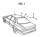
- An on-board antenna 10 is, as shown in Figs. 1 and 2, disposed on, for example, a passenger compartment-side inner surface 2A of a peripheral edge portion 2a of a rearwindow glass, for example, of window glasses of a vehicle 1.
- this on-board antenna 10 is may be, for example, a GPS (Global Position System) antenna used in receiving a positioning signal from a GPS communications network for measuring the position of a vehicle by making use of an artificial earth satellite or transmitting an emergency message by making use of positional information from GPS, for example, a DSRC (Dedicated Short Range Communications) antenna used in receiving data distributed from various types of information providing services or implementing a process of automatic toll collection through a narrow area radio communications DSRC between roadside radio equipment and on-board radio equipment, for example, an antenna for receiving data distributed from broadcasting and/or various types of information providing services which utilize an artificial earth satellite, or, for example, a mobile communications antenna used for mobile communications between an artificial earth satellite or appropriate base station and the vehicle.
- GPS Global Position System
- DSRC Dedicated Short Range Communications
- the on-board antenna 10 includes, for example, a planar antenna 11 disposed on a passenger compartment-side inner surface 2A of a rear window glass 2 which functions as a dielectric substrate, and the planar antenna 11 includes, for example, as shown in Fig. 3, a radiation element 21 comprising a conductive film disposed on the passenger compartment-side inner surface 2A of the rear window glass 2 and a grounding conductor 22.
- the radiation element 21 is formed such that, in a substantially quadrangular conductive film having two pairs of two opposing sides, for example, apair of two corner portions of two pairs of two opposing corner portions which are formed by two adjacent sides which intersect each other substantially at right angles is cut so as to form substantially linear perturbative portions 21a, 21a, so that a circularly polarized wave mode is generated by these perturbative portions 21a, 21a.
- an inner edge portion of the inner cut-out portion 23 is formed so as to have a configuration which follows an outer edge portion of the radiation element 21 at a position spaced away inwardly a predetermined widthwise distance from the outer edge portion.
- substantially linear corner portions 23a, 23a which follow, respectively, a pair of substantially linear perturbative portions 21a, 21a formed on the outer edge portion of the radiation element 21 are formed at a pair of two corner portions of two pairs of two opposing corner portions on the inner edge portion of the inner cut-out portion 23.
- the radiation element 21 is connected to an appropriate feeding line (not shown) so that an appropriate high-frequency electric current is fed thereto.
- the grounding conductor 22 is formed into a substantially quadrangular annular conductive film and is connected to an appropriate ground wire (not shown) so as to be grounded at all times.
- the grounding conductor 22 is disposed so as to surround the periphery of an outer edge portion of the radiation element 21 provided on the passenger compartment-side inner surface 2A of the rear window glass 2 at a position spaced away outwardly from the outer edge portion.
- the passenger compartment-side inner surface 2A of the rear window glass 2 which is made to function as the dielectric substrate is exposed between the outer edge portion of the radiation element 21 and an inner edge portion of the grounding conductor 22, and the planar antenna 11 is made to function as an antenna when a so-called resonance circuit is formed between the radiation element 21 and the grounding conductor 22.
- the permitivity of the rear window glass 2 made to function as the dielectric substrate respective lengths of the two pairs of opposing sides of the radiation element 21 and the distance between the outer edge portion of the radiation element 21 and the inner edge portion of the grounding conductor 22 are set to appropriate values.
- the respective lengths of two pairs of two opposing sides of the radiation element 21 are set to lengths which are smaller by predetermined extents than lengths that are set in a state in which the inner cut-out portion 23 is not provided.
- the resonant frequency can be decreased when compared to a case where no inner cut-out portion 23 is provided in a radiation element having the same external size as that of the radiation element 21.
- an anticipated decrease in resonant frequency that would be caused by the provision of the inner cut-out portion 23 can be compensated for by setting the external size (for example, the respective lengths La of the two pairs of two opposing sides) of the radiation element 21 in which the inner cut-out portion 23 is provided smaller than an external size (for example, the respective lengths Lb of two pairs of two opposing sides) of a radiation element 31 of a planar antenna 30 which is set to secure a desired resonant frequency in a state in which no inner cut-out portion 23 is provided.
- the external size for example, the respective lengths La of the two pairs of two opposing sides
- an external size for example, the respective lengths Lb of two pairs of two opposing sides
- the planar antenna 30 in which no inner cut-but portion 23 is provided includes the radiation element 31 having perturbative portions 31a, 31a which are formed by cutting a pair of corner portions of a substantially rectangular conductive film and a grounding conductor 32 disposed in such a manner as to surround the periphery of an outer edge portion of the radiation element 31 at a position spaced away outwardly from the outer edge portion.
- a change according to an elevation angle ⁇ in average value (average sensitivity) dBa around a vertical axis (an axis Z shown in Fig. 1) of a sensitivity or gain relative to a radio wave at a desired resonant frequency of the on-board antenna 10 becomes substantially similar to the sensitivity Db of the planar antenna 30 having no inner cut-out portion 23 which is shown in Fig. 5B, for example.
- a desired directional property can be secured, as with the sensitivity Db of the planar antenna 30 having no inner cut-out portion 23 which is shown in Fig. 6B, for example.
- the resonant frequency can be decreased further while securing desired properties of sensitivity when compared to the radiation element 30 in which the inner cut-out portion 23 is not provided, whereby, in an attempt to secure a desired resonant frequency for the radiation element 21 in which the inner cut-out portion 23 is provided, the external size of the radiation element 21 can be made smaller than that of the radiation element 30 in which the inner cut-out portion 23 is not provided.
- the external size of the grounding conductor 22 can be decreased, and as a result, the on-board antenna 10 can be made smaller in size.
- the planar antenna 11 is made to include the radiation conductor 21 which is formed of the conductive film and the grounding conductor, the present invention is not limited thereto.
- a radiation element formed of a semiconductor may be provided in place of the radiation conductor 21.
- the resonant frequency can be decreased further while securing desired properties of sensitivity when compared to the radiation element in which the inner cut-out portion is not provided, whereby, in an attempt to secure a desired resonant frequency for the radiation element in which the inner cut-out portion is provided, the size of the radiation element can be made smaller than that of the radiation element in which the. inner cut-out portion is not provided. Namely, the areas of the radiation element and the grounding conductor which are placed on the dielectric substrate can be decreased.
- An on-board antenna including a radiation element provided on a dielectric substrate, and a grounding conductor surrounding a periphery of an outer edge portion of the radiation element at a position spaced away outwardly from the outer edge portion, wherein the radiation element has an inner cut-out portion so that the surface of the dielectric substrate to be exposed therethrough.
Landscapes
- Details Of Aerials (AREA)
- Waveguide Aerials (AREA)
Abstract
Description
Claims (6)
- An on-board antenna comprising:wherein the radiation element has an inner cut-out portion so that the surface of the dielectric substrate to be exposed therethrough.a radiation element provided on a dielectric substrate; anda grounding conductor surrounding a periphery of an outer edge portion of the radiation element at a position spaced away outwardly from the outer edge portion;
- An on-board antenna as set forth in Claim 1, wherein the radiation element is a substantially quadrangular film having two pairs of two opposing corner portions, and the one pair of two corner portions is cut so as to form substantially linear perturbative portions.
- An on-board antenna as set forth in Claim 1, wherein the radiation element is circular-shape having a predetermined width.
- An on-board antenna as set forth in Claim 1, wherein an inner edge portion of the inner cut-out portion follows an outer edge portion of the radiation element at a position spaced away inwardly a predetermined widthwise distance from the outer edge portion of the radiation element.
- An on-board antenna as set forth in Claim 1, wherein an external size of the on-board antenna with the inner cut-out portion is smaller than that of an on-board antenna without the inner cut-out portion.
- An on-board antenna as set forth in Claim 1, wherein the radiation element is a semiconductor.
Applications Claiming Priority (2)
| Application Number | Priority Date | Filing Date | Title |
|---|---|---|---|
| JP2002379995A JP2004214821A (en) | 2002-12-27 | 2002-12-27 | In-vehicle antenna |
| JP2002379995 | 2002-12-27 |
Publications (2)
| Publication Number | Publication Date |
|---|---|
| EP1434302A1 true EP1434302A1 (en) | 2004-06-30 |
| EP1434302B1 EP1434302B1 (en) | 2007-09-26 |
Family
ID=32463629
Family Applications (1)
| Application Number | Title | Priority Date | Filing Date |
|---|---|---|---|
| EP03029744A Expired - Lifetime EP1434302B1 (en) | 2002-12-27 | 2003-12-23 | Annular-slot antenna |
Country Status (4)
| Country | Link |
|---|---|
| US (1) | US7019699B2 (en) |
| EP (1) | EP1434302B1 (en) |
| JP (1) | JP2004214821A (en) |
| DE (1) | DE60316531T2 (en) |
Families Citing this family (12)
| Publication number | Priority date | Publication date | Assignee | Title |
|---|---|---|---|---|
| USD549696S1 (en) * | 2004-07-15 | 2007-08-28 | Nippon Sheet Glass Company, Limited | Planar antenna element for vehicle windowpane |
| USD544469S1 (en) * | 2004-07-15 | 2007-06-12 | Nippon Sheet Glass Company, Limited | Planar antenna element for vehicle window pane |
| US7253770B2 (en) * | 2004-11-10 | 2007-08-07 | Delphi Technologies, Inc. | Integrated GPS and SDARS antenna |
| US7834815B2 (en) * | 2006-12-04 | 2010-11-16 | AGC Automotive America R & D, Inc. | Circularly polarized dielectric antenna |
| US8009107B2 (en) * | 2006-12-04 | 2011-08-30 | Agc Automotive Americas R&D, Inc. | Wideband dielectric antenna |
| US7994999B2 (en) * | 2007-11-30 | 2011-08-09 | Harada Industry Of America, Inc. | Microstrip antenna |
| EP2223385B1 (en) * | 2007-12-17 | 2015-10-28 | Siemens Aktiengesellschaft | Planar broadband antenna |
| US7548207B1 (en) * | 2008-02-06 | 2009-06-16 | Advanced Connection Technology, Inc. | Circularly polarized antenna |
| JP4647678B2 (en) * | 2008-08-18 | 2011-03-09 | 株式会社エヌ・ティ・ティ・ドコモ | Message distribution method, radio base station, and message distribution station |
| USD704682S1 (en) * | 2013-08-21 | 2014-05-13 | Avery Dennison Corporation | RFID antenna |
| USD706246S1 (en) * | 2013-09-10 | 2014-06-03 | Avery Dennison Corporation | RFID device |
| USD716774S1 (en) * | 2014-04-04 | 2014-11-04 | Avery Dennison Corporation | RFID inlay |
Citations (2)
| Publication number | Priority date | Publication date | Assignee | Title |
|---|---|---|---|---|
| WO1996010276A1 (en) * | 1994-09-28 | 1996-04-04 | Wireless Access Incorporated | Ring microstrip antenna array |
| JP2002252520A (en) * | 2001-02-22 | 2002-09-06 | Asahi Glass Co Ltd | Planar antenna |
Family Cites Families (13)
| Publication number | Priority date | Publication date | Assignee | Title |
|---|---|---|---|---|
| US4682180A (en) * | 1985-09-23 | 1987-07-21 | American Telephone And Telegraph Company At&T Bell Laboratories | Multidirectional feed and flush-mounted surface wave antenna |
| DE69417106T2 (en) * | 1993-07-01 | 1999-07-01 | The Commonwealth Scientific And Industrial Research Organization, Campbell | Plane antenna |
| US5568159A (en) * | 1994-05-12 | 1996-10-22 | Mcdonnell Douglas Corporation | Flared notch slot antenna |
| GB9410557D0 (en) * | 1994-05-26 | 1994-07-13 | Schlumberger Ind Ltd | Radio antennae |
| US5629712A (en) * | 1995-10-06 | 1997-05-13 | Ford Motor Company | Vehicular slot antenna concealed in exterior trim accessory |
| DE19628125A1 (en) * | 1996-07-12 | 1998-01-15 | Daimler Benz Ag | Active receiving antenna |
| JPH11251829A (en) * | 1998-02-27 | 1999-09-17 | Kyocera Corp | Slot antenna and wiring board provided with the same |
| FR2779276B1 (en) * | 1998-05-28 | 2000-07-13 | Alsthom Cge Alcatel | RADIO COMMUNICATION DEVICE AND LOOP SLOT ANTENNA |
| US6246377B1 (en) * | 1998-11-02 | 2001-06-12 | Fantasma Networks, Inc. | Antenna comprising two separate wideband notch regions on one coplanar substrate |
| US6097345A (en) * | 1998-11-03 | 2000-08-01 | The Ohio State University | Dual band antenna for vehicles |
| US6329950B1 (en) * | 1999-12-06 | 2001-12-11 | Integral Technologies, Inc. | Planar antenna comprising two joined conducting regions with coax |
| MXPA02007453A (en) * | 2000-02-11 | 2002-12-13 | Ppg Ind Ohio Inc | Vehicle antenna. |
| FR2826185B1 (en) * | 2001-06-18 | 2008-07-11 | Centre Nat Rech Scient | MULTI-FREQUENCY WIRE-PLATE ANTENNA |
-
2002
- 2002-12-27 JP JP2002379995A patent/JP2004214821A/en active Pending
-
2003
- 2003-12-23 DE DE60316531T patent/DE60316531T2/en not_active Expired - Fee Related
- 2003-12-23 EP EP03029744A patent/EP1434302B1/en not_active Expired - Lifetime
- 2003-12-24 US US10/743,942 patent/US7019699B2/en not_active Expired - Fee Related
Patent Citations (2)
| Publication number | Priority date | Publication date | Assignee | Title |
|---|---|---|---|---|
| WO1996010276A1 (en) * | 1994-09-28 | 1996-04-04 | Wireless Access Incorporated | Ring microstrip antenna array |
| JP2002252520A (en) * | 2001-02-22 | 2002-09-06 | Asahi Glass Co Ltd | Planar antenna |
Non-Patent Citations (2)
| Title |
|---|
| PATENT ABSTRACTS OF JAPAN vol. 2003, no. 01 14 January 2003 (2003-01-14) * |
| WEN-SHYANG CHEN ET AL: "Single-feed circularly polarized square-ring microstrip antennas with a slit", ANTENNAS AND PROPAGATION SOCIETY INTERNATIONAL SYMPOSIUM, 1998. IEEE ATLANTA, GA, USA 21-26 JUNE 1998, NEW YORK, NY, USA,IEEE, US, 21 June 1998 (1998-06-21), pages 1360 - 1363, XP010292067, ISBN: 0-7803-4478-2 * |
Also Published As
| Publication number | Publication date |
|---|---|
| US7019699B2 (en) | 2006-03-28 |
| DE60316531D1 (en) | 2007-11-08 |
| EP1434302B1 (en) | 2007-09-26 |
| US20040135728A1 (en) | 2004-07-15 |
| DE60316531T2 (en) | 2008-01-31 |
| JP2004214821A (en) | 2004-07-29 |
Similar Documents
| Publication | Publication Date | Title |
|---|---|---|
| US6924774B2 (en) | On-board antenna | |
| EP2453521B1 (en) | Windowpane for vehicle and antenna | |
| US7286098B2 (en) | Circular polarization antenna and composite antenna including this antenna | |
| US5973648A (en) | Radio antenna arrangement with a patch antenna for mounting on or adjacent to the windshield of a vehicle | |
| US7321338B2 (en) | On-board antenna | |
| US6788255B2 (en) | Antenna unit having radio absorbing device | |
| US7019699B2 (en) | On-board antenna | |
| KR100890967B1 (en) | Loop antenna attached to rear glass of vehicles | |
| EP2136434B1 (en) | Structure for rectangular loop antenna | |
| US6930645B2 (en) | Automotive on-board antenna | |
| US6292149B1 (en) | All-around vehicle antenna apparatus | |
| JP2002252520A (en) | Planar antenna | |
| US6995722B2 (en) | On-board antenna | |
| KR102215657B1 (en) | Multi-band antenna and antenna assembly comprising the same for vehicle | |
| US6900766B2 (en) | Vehicle antenna | |
| JP4659723B2 (en) | Antenna device | |
| JP3230965B2 (en) | Front end for roadside beacon system | |
| JP2004172875A (en) | Board antenna | |
| US20070080876A1 (en) | Planar antenna and window glass sheet for automobiles | |
| JP2003017931A (en) | Planar antenna structure | |
| KR20070118536A (en) | Automotive High Frequency Glass Antenna | |
| JPH056919U (en) | In-vehicle flat antenna |
Legal Events
| Date | Code | Title | Description |
|---|---|---|---|
| PUAI | Public reference made under article 153(3) epc to a published international application that has entered the european phase |
Free format text: ORIGINAL CODE: 0009012 |
|
| AK | Designated contracting states |
Kind code of ref document: A1 Designated state(s): AT BE BG CH CY CZ DE DK EE ES FI FR GB GR HU IE IT LI LU MC NL PT RO SE SI SK TR |
|
| AX | Request for extension of the european patent |
Extension state: AL LT LV MK |
|
| 17P | Request for examination filed |
Effective date: 20041020 |
|
| AKX | Designation fees paid |
Designated state(s): DE FR GB |
|
| 17Q | First examination report despatched |
Effective date: 20050223 |
|
| GRAP | Despatch of communication of intention to grant a patent |
Free format text: ORIGINAL CODE: EPIDOSNIGR1 |
|
| GRAS | Grant fee paid |
Free format text: ORIGINAL CODE: EPIDOSNIGR3 |
|
| GRAA | (expected) grant |
Free format text: ORIGINAL CODE: 0009210 |
|
| AK | Designated contracting states |
Kind code of ref document: B1 Designated state(s): DE FR GB |
|
| REG | Reference to a national code |
Ref country code: GB Ref legal event code: FG4D |
|
| REF | Corresponds to: |
Ref document number: 60316531 Country of ref document: DE Date of ref document: 20071108 Kind code of ref document: P |
|
| ET | Fr: translation filed | ||
| PLBE | No opposition filed within time limit |
Free format text: ORIGINAL CODE: 0009261 |
|
| STAA | Information on the status of an ep patent application or granted ep patent |
Free format text: STATUS: NO OPPOSITION FILED WITHIN TIME LIMIT |
|
| 26N | No opposition filed |
Effective date: 20080627 |
|
| PGFP | Annual fee paid to national office [announced via postgrant information from national office to epo] |
Ref country code: FR Payment date: 20081212 Year of fee payment: 6 |
|
| PGFP | Annual fee paid to national office [announced via postgrant information from national office to epo] |
Ref country code: DE Payment date: 20081219 Year of fee payment: 6 |
|
| PGFP | Annual fee paid to national office [announced via postgrant information from national office to epo] |
Ref country code: GB Payment date: 20081217 Year of fee payment: 6 |
|
| PG25 | Lapsed in a contracting state [announced via postgrant information from national office to epo] |
Ref country code: FR Free format text: LAPSE BECAUSE OF NON-PAYMENT OF DUE FEES Effective date: 20091231 |
|
| GBPC | Gb: european patent ceased through non-payment of renewal fee |
Effective date: 20091223 |
|
| PG25 | Lapsed in a contracting state [announced via postgrant information from national office to epo] |
Ref country code: DE Free format text: LAPSE BECAUSE OF NON-PAYMENT OF DUE FEES Effective date: 20100701 |
|
| PG25 | Lapsed in a contracting state [announced via postgrant information from national office to epo] |
Ref country code: GB Free format text: LAPSE BECAUSE OF NON-PAYMENT OF DUE FEES Effective date: 20091223 |
|
| REG | Reference to a national code |
Ref country code: FR Ref legal event code: ST Effective date: 20110826 |