EP1434159A2 - Integrated antenna type non-contact IC card reader/writer - Google Patents
Integrated antenna type non-contact IC card reader/writer Download PDFInfo
- Publication number
- EP1434159A2 EP1434159A2 EP03029456A EP03029456A EP1434159A2 EP 1434159 A2 EP1434159 A2 EP 1434159A2 EP 03029456 A EP03029456 A EP 03029456A EP 03029456 A EP03029456 A EP 03029456A EP 1434159 A2 EP1434159 A2 EP 1434159A2
- Authority
- EP
- European Patent Office
- Prior art keywords
- contact
- loop antenna
- card reader
- writer
- antenna
- Prior art date
- Legal status (The legal status is an assumption and is not a legal conclusion. Google has not performed a legal analysis and makes no representation as to the accuracy of the status listed.)
- Withdrawn
Links
Images


Classifications
-
- G—PHYSICS
- G06—COMPUTING; CALCULATING OR COUNTING
- G06K—GRAPHICAL DATA READING; PRESENTATION OF DATA; RECORD CARRIERS; HANDLING RECORD CARRIERS
- G06K7/00—Methods or arrangements for sensing record carriers, e.g. for reading patterns
- G06K7/10—Methods or arrangements for sensing record carriers, e.g. for reading patterns by electromagnetic radiation, e.g. optical sensing; by corpuscular radiation
- G06K7/10009—Methods or arrangements for sensing record carriers, e.g. for reading patterns by electromagnetic radiation, e.g. optical sensing; by corpuscular radiation sensing by radiation using wavelengths larger than 0.1 mm, e.g. radio-waves or microwaves
- G06K7/10316—Methods or arrangements for sensing record carriers, e.g. for reading patterns by electromagnetic radiation, e.g. optical sensing; by corpuscular radiation sensing by radiation using wavelengths larger than 0.1 mm, e.g. radio-waves or microwaves using at least one antenna particularly designed for interrogating the wireless record carriers
- G06K7/10346—Methods or arrangements for sensing record carriers, e.g. for reading patterns by electromagnetic radiation, e.g. optical sensing; by corpuscular radiation sensing by radiation using wavelengths larger than 0.1 mm, e.g. radio-waves or microwaves using at least one antenna particularly designed for interrogating the wireless record carriers the antenna being of the far field type, e.g. HF types or dipoles
-
- G—PHYSICS
- G06—COMPUTING; CALCULATING OR COUNTING
- G06K—GRAPHICAL DATA READING; PRESENTATION OF DATA; RECORD CARRIERS; HANDLING RECORD CARRIERS
- G06K7/00—Methods or arrangements for sensing record carriers, e.g. for reading patterns
- G06K7/10—Methods or arrangements for sensing record carriers, e.g. for reading patterns by electromagnetic radiation, e.g. optical sensing; by corpuscular radiation
- G06K7/10009—Methods or arrangements for sensing record carriers, e.g. for reading patterns by electromagnetic radiation, e.g. optical sensing; by corpuscular radiation sensing by radiation using wavelengths larger than 0.1 mm, e.g. radio-waves or microwaves
- G06K7/10316—Methods or arrangements for sensing record carriers, e.g. for reading patterns by electromagnetic radiation, e.g. optical sensing; by corpuscular radiation sensing by radiation using wavelengths larger than 0.1 mm, e.g. radio-waves or microwaves using at least one antenna particularly designed for interrogating the wireless record carriers
- G06K7/10336—Methods or arrangements for sensing record carriers, e.g. for reading patterns by electromagnetic radiation, e.g. optical sensing; by corpuscular radiation sensing by radiation using wavelengths larger than 0.1 mm, e.g. radio-waves or microwaves using at least one antenna particularly designed for interrogating the wireless record carriers the antenna being of the near field type, inductive coil
Definitions
- the present invention relates to a neighborhood type (The correspondence distance is approximately 1 m.) non-contact IC card reader/writer by which electric power and sending data are supplied to a non-contact IC card, and receiving data is acquired from the non-contact IC card by a change in the load. That is, the present invention relates to an integrated antenna type non-contact IC card reader/writer, the size of which is reduced when the antenna and the control board are integrated into one body.
- a reader/writer system using IC cards is generally referred to as an IC card system.
- this reader/writer system is being put into practical use for the physical distribution system, traffic system and air freight management system in which the frequency band of 13.56 MHz is used.
- This system includes: an IC card on which an IC chip and antenna coil are provided on one piece of card made of resin; and a reader/writer conducting correspondence with this IC card.
- This reader/writer is provided with a loop antenna, which constantly or intermittently sends electric power and sending data and acquires receiving data from IC card located in a range capable of receiving electric power and sending data.
- a conventional non-contact IC card system and loop antenna described in " Official gazette of JP-A-2002-279362" are shown in Fig. 5.
- Fig. 5 is a conceptional view showing a conventional non-contact IC card reader/writer.
- the antenna (loop antenna) 201 and reader/writer (R/W) 203 are connected with each other by the coaxial cable 202. Further, the reader/writer 203 is connected with the control unit 204.
- the non-contact IC card (IC tag) 207 is stuck on the load 206 conveyed on the conveyance line 205.
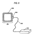
- FIG. 6 is a simplified view showing a conventional non-contact IC card reader/writer.
- the conventional neighborhood type non-contact IC card reader/writer includes: an antenna portion composed of the loop antenna 208 and the antenna radome 209 made of resin for accommodating the loop antenna 208; and a reader/writer 203 for supplying electric power and sending data to the antenna portion 201 and for acquiring receiving data.
- the antenna portion 201 and the reader/writer 203 are connected with each other by the coaxial cable 202.
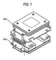
- FIG. 7 is a conceptional view showing a conventional non-contact IC card reader/writer.
- the conventional neighborhood type non-contact IC card reader/writer is assembled in such a manner that the antenna portion 201 and the control board 210 are made to come close to each other being laminated on each other. Therefore, a size of the entire device in the thickness direction is increased and an entire region on one side of the antenna opening is substantially covered with the control board 210.
- the antenna portion 201 and the reader/writer 203 are separate from each other and connected by the coaxial cable 202. Due to this constitution, the following problems may be encountered.
- the coaxial cable 202 is laid round the device, the neighboring antenna 201 is affected by the coaxial cable 202, and the resonance frequency is shifted (transition of the resonance frequency). Accordingly, it becomes necessary to adjust the resonance frequency by a trimmer condenser (not shown) provided in the antenna resonance circuit.
- the conventional neighborhood type non-contact IC card reader/writer shown in Fig. 7 is assembled in such a manner that the antenna portion 201 and the control board 210 are made to come close to each other being laminated on each other. Therefore, a size of the entire device in the thickness direction is increased and an entire region on one side of the antenna opening is substantially covered with the control board 210. Accordingly, an electromagnetic field generated by the antenna is interrupted. Therefore, even when an intensity of electric power of sending is increased, the electric power to be sent into the space is lost, which decreases a distance of correspondence.
- the present invention has been accomplished to solve the above problems. It is an object of the present invention to provide a small thin integrated antenna type non-contact IC card reader/writer, the characteristic of which is stable, characterized in that: the device is seldom affected by the restriction of a place in which the device is installed; the device is seldom affected even when the coaxial cable is laid round the device; and it is unnecessary to adjust the resonance frequency of the antenna, so that the device can be easily installed.
- the present invention provides an integrated antenna type non-contact IC card reader/writer comprising: a circular or substantially rectangular or polygonal loop antenna for supplying electric power and sending data to a non-contact IC card by electromagnetic induction and for acquiring receiving data from the non-contact IC card by a change in the load; a resonance matching circuit composing a resonance circuit for making the loop antenna resonate with a desired frequency and also composing a matching circuit for matching impedance with a transmission line; a wireless sending portion for supplying electric power and sending data to the loop antenna via the resonance matching circuit; a wireless receiving portion for acquiring receiving data from the loop antenna via the resonance matching circuit; and a control board on which the resonance matching circuit and a control portion for controlling the wireless sending portion and the wireless receiving portion are mounted, the control board being accommodated in a shielded case, wherein the components are arranged and assembled so that a central axis of the loop antenna in the thickness direction and a central axis of the shielded case in the thickness direction can
- the present invention provides an integrated antenna type non-contact IC card reader/writer comprising: a circular or substantially rectangular or polygonal loop antenna for supplying electric power and sending data to a non-contact IC card by electromagnetic induction and for acquiring receiving data from the non-contact IC card by a change in the load; a resonance matching circuit composing a resonance circuit for making the loop antenna resonate with a desired frequency and also composing a matching circuit for matching impedance with a transmission line; a wireless sending portion for supplying electric power and sending data to the loop antenna via the resonance matching circuit; a wireless receiving portion for acquiring receiving data from the loop antenna via the resonance matching circuit; and a control board on which the resonance matching circuit and a control portion for controlling the wireless sending portion and the wireless receiving portion are mounted, the control board being accommodated in a shielded case, wherein the loop antenna and the shielded case are arranged and assembled on the same plane being adjacent to each other.
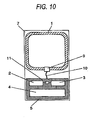
- Fig. 10 is a plan view showing an integrated antenna type non-contact IC card reader/writer of Embodiment 2 of the present invention.
- Fig. 11 is a plan view showing an integrated antenna type non-contact IC card reader/writer of Embodiment 3 of the present invention.
- the definition of the non-contact type IC card of the present invention is not limited to a so-called card.
- the definition of the non-contact type IC card of the present invention includes a wireless correspondence medium capable of corresponding with a reader/writer in a state of non-contact.
- the non-contact type IC card of the present invention includes an IC tag, ID tag and identification label.
- a reading/writing apparatus corresponds to an apparatus which is communicated with the above-described wireless communication media. Then, the reading/writing apparatus reads information from the wireless communication media, and writes information into the wireless communication media. It should be understood that the reading/writing apparatus performs at least any one of information reading/writing operations, depending upon use purposes.
- An integrated antenna type non-contact IC card reader/writer comprises: a circular or substantially rectangular or polygonal loop antenna for supplying electric power and sending data to a non-contact IC card by electromagnetic induction and for acquiring receiving data from the non-contact IC card by a change in the load; a resonance matching circuit composing a resonance circuit for making the loop antenna resonate with a desired frequency and also composing a matching circuit for matching impedance with a transmission line; a wireless sending portion for supplying electric power and sending data to the loop antenna via the resonance matching circuit; a wireless receiving portion for acquiring receiving data from the loop antenna via the resonance matching circuit; and a control board on which the resonance matching circuit and a control portion for controlling the wireless sending portion and the wireless receiving portion are mounted, the control board being accommodated in a shielded case, wherein the components are arranged and assembled so that a central axis of the loop antenna in the thickness direction and a central axis of the shielded case in the thickness direction can be made to substantially coincide with each other.
- the control board on which the control portion for controlling the wireless sending portion and the wireless receiving portion is mounted, is accommodated in the shielded case, unnecessary electromagnetic waves can be prevented from leaking out and obstructive electromagnetic waves coming from the outside can be prevented from intruding into the device. Further, sending signals emitted from the device itself can be prevented from spreading out into the receiving circuit.
- the loop antenna and the shielded - case are arranged and assembled so that the central axis of the loop antenna in the thickness direction and the central axis of the shielded case in the thickness direction can substantially coincide with each other, length of the entire device in the thickness direction can be reduced, and the device can be easily transported and installed.
- the integrated antenna type non-contact IC card reader/writer wherein the loop antenna and the shielded case are arranged and assembled so that a central axis of the loop antenna in the longitudinal direction and a central axis of the shielded case in the longitudinal direction can be made to coincide with each other on an opening face of the loop antenna.
- the directivity of the antenna can be made to pass through the center 0 of the loop antenna in the longitudinal direction (Y-axis) and an intensity of the electromagnetic field can be maximized on axis Z - Z' perpendicular to Y-axis.
- the integrated antenna type non-contact IC card reader/writer wherein the loop antenna and the shielded case are arranged and assembled so that a central axis of the loop antenna in the lateral direction and a central axis of the shielded case in the lateral direction can be made to coincide with each other on an opening face of the loop antenna.
- the directivity of the antenna is made to pass through the center 0 of the loop antenna in the lateral direction (X-axis) and an intensity of the electromagnetic field can be maximized on axis Z - Z' perpendicular to X-axis.
- the integrated antenna type non-contact IC card reader/writer wherein an area ratio of the loop antenna to the shield case accommodating the control board, on which the control portion for controlling the wireless sending portion and wire less receiving portion is mounted, is substantially 1 to 1/4 or less. Since an area of the antenna opening corresponding to 3/4 of the entire antenna opening is open, the electromagnetic field generated by the antenna is seldom interrupted. Therefore, it becomes possible to substantially reduce the deterioration of the corresponding distance to zero.
- the integrated antenna type non-contact IC card reader/writer wherein the resonance matching circuit is arranged close to the loop antenna and connected with it, and a coaxial cable, the length of which is substantially 1/4 or less of the maximum diameter of the loop antenna, is used for supplying and receiving electric power and sending and receiving data between the resonance matching circuit and the wireless sending portion and also between the resonance matching circuit and the wireless receiving portion. Since length of the coaxial cable is determined to be about 1/4 or less of the maximum diameter of the loop antenna, the degree of freedom can be increased in the process of manufacturing the device. Accordingly, assembling can be more easily performed, and electric length of the coaxial cable can be shortened. Therefore, the cable transmission loss caused by laying the coaxial cable round the device can be reduced.
- the integrated antenna type non-contact IC card reader/writer wherein the loop antenna is directly connected with a micro strip line transmission line, which extends from the resonance matching circuit provided on the control board, for supplying and receiving electric power and sending and receiving data between the loop antenna and the wireless sending portion and also between the loop antenna and the wireless receiving portion. Since the coaxial cable is avoided in this structure, a bad influence caused by laying the coaxial cable round the device and a cable transmission loss can be avoided, and further an assembling process can be reduced in the case of manufacturing the device.
- the integrated antenna type non-contact IC card reader/writer wherein the loop antenna and shielded case are accommodated in one case made of resin. Since the device is accommodated in one case made of resin, installation can be more easily performed.
- An integrated antenna type non-contact IC card reader/writer comprising: a loop antenna for corresponding with a wireless correspondence medium such as a non-contact IC card; and a control board on which a correspondence control means for corresponding between the wireless correspondence medium and the loop antenna is mounted, wherein the control board on which the correspondence control means is mounted is arranged in an opening of the loop antenna. Therefore, the device itself can be reduced in size.
- the integrated antenna type non-contact IC card reader/writer wherein the control board, on which the correspondence control means is mounted, is accommodated in a shielded case. Unnecessary electromagnetic waves can be prevented from leaking out and obstructive electromagnetic waves coming from the outside can be prevented from intruding into the device. Further, sending signals emitted from the device itself can be prevented from spreading out into the receiving circuit.
- the an integrated antenna type non-contact IC card reader/writer wherein the loop antenna and the control board, on which and the correspondence control means is mounted, are accommodated in one housing. Therefore, the installation of the device can be more easily performed.
- the present invention can provide a small thin integrated antenna type non-contact IC card reader/writer characterized in that: the device is seldom affected by the restriction of a place in which the device is installed; and it is unnecessary to adjust the resonance frequency of the antenna, so that the device can be easily installed.
- An integrated antenna type non-contact IC card reader/writer comprises: a circular or substantially rectangular or polygonal loop antenna for supplying electric power and sending data to a non-contact IC card by electromagnetic induction and for acquiring receiving data from the non-contact IC card by a change in the load; a resonance matching circuit composing a resonance circuit for making the loop antenna resonate with a desired frequency and also composing a matching circuit for matching impedance with a transmission line; a wireless sending portion for supplying electric power and sending data to the loop antenna via the resonance matching circuit; a wireless receiving portion for acquiring receiving data from the loop antenna via the resonance matching circuit; and a control board on which the resonance matching circuit and a control portion for controlling the wireless sending portion and the wireless receiving portion are mounted, the control board being accommodated in a shielded case, wherein the loop antenna and the shielded case are arranged and assembled on the same plane being adjacent to each other.
- the resonance matching circuit and the control board, on which the control portion for controlling the wireless sending portion and the wireless receiving portion is mounted are accommodated in the shielded case, unnecessary electromagnetic waves can be prevented from leaking out and obstructive electromagnetic waves coming from the outside can be prevented from intruding into the device. Further, it is possible to prevent the sending signal, which is emitted by the device itself, from coming into the receiving circuit.
- the loop antenna and the shielded case are arranged and assembled on the same plane being adjacent to each other, a bad influence caused by laying the coaxial cable at the time of installing can be avoided, and a shift (transition) of the resonance frequency caused by the influence of the coaxial cable can be avoided. Therefore, it becomes unnecessary to adjust the resonance frequency.
- the integrated antenna type non-contact -IC card reader/writer wherein the resonance matching circuit is arranged close to the loop antenna and connected with it, and a coaxial cable, the length of which is substantially 1/4 or less of the maximum diameter of the loop antenna, is used for supplying and receiving electric power and sending and receiving data between the resonance matching circuit and the wireless sending portion and also between the resonance matching circuit and the wireless receiving portion. Since length of the coaxial cable is determined to be about 1/4 or less of the maximum diameter of the loop antenna, the degree of freedom can be increased in the process of manufacturing the device. Accordingly, assembling can be more easily performed, and electric length of the coaxial cable can be shortened. Therefore, the cable transmission loss caused by laying the coaxial cable round the device can be reduced.
- the integrated antenna type non-contact IC card reader/writer wherein the loop antenna is directly connected with a micro strip line transmission line, which extends from the resonance matching circuit provided on the control board, for supplying and receiving electric power and sending and receiving data between the loop antenna and the wireless sending portion and also between the loop antenna and the wireless receiving portion. Since the coaxial cable is avoided in this structure, a bad influence caused by laying the coaxial cable round the device and a cable transmission loss can be avoided, and further an assembling process can be reduced in the process of manufacturing the device.
- the integrated antenna type non-contact IC card reader/writer wherein the loop antenna and shielded case are accommodated in one case made of resin. Since the device is accommodated in one case made of resin, installation can be more easily performed.
- An integrated antenna type non-contact IC card reader/writer comprising: a loop antenna for corresponding with a wireless correspondence medium such as a non-contact IC card; and a control board on which a correspondence control means for corresponding between the wireless correspondence medium and the loop antenna is mounted, wherein the loop antenna and the control board, on which the correspondence control means is mounted, are arranged on the same plane being adjacent to each other.
- the integrated antenna type non-contact IC card reader/writer wherein the control board, on which the correspondence control means is mounted, is accommodated in a shielded case. Unnecessary electromagnetic waves can be prevented from leaking out and obstructive electromagnetic waves coming from the outside can be prevented from intruding into the device. Further, sending signals emitted from the device itself can be prevented from spreading out into the receiving circuit.
- the integrated antenna type non-contact IC card reader/writer wherein the control board, on which the loop antenna and the correspondence control means are mounted, is accommodated in one housing. Therefore, the installation of the device can be more easily performed.
- the present invention can provide a small thin integrated antenna type non-contact IC card reader/writer characterized in that: the device is seldom affected by the restriction of a place in which the device is installed; and it is unnecessary to adjust the resonance frequency of the antenna, so that the device can be easily installed.
- Fig. 1 is a perspective see-through view showing an integrated antenna type non-contact IC card reader/writer of Embodiment 1 of the present invention
- Fig. 2 is a view for explaining operation of the integrated antenna type non-contact IC card system in Embodiment 1 of the present invention.
- reference numeral 1 is a loop antenna, which supplies electric power and sending data to non-contact IC card 102 described later and acquires receiving data from non-contact IC card 102 by a change in the load.
- Reference numeral 2 is a wireless sending portion for supplying electric power and sending data to the loop antenna 1
- reference numeral 3 is a wireless receiving portion for acquiring receiving data from the loop antenna 1
- reference numeral 4 is a control portion for controlling the wireless sending portion 2 and the wireless receiving portion 3
- reference numeral 5 is a control board on which the wireless sending portion 2, the wireless receiving portion 3 and the control portion 4 are mounted
- reference numeral 6 is a shielded case in which the wireless sending portion 2, the wireless receiving portion 3, the control portion 4 and the control board 5 are accommodated.
- Reference numeral 7 is a case made of resin in which the loop antenna 1, the wireless sending portion 2, the wireless receiving portion 3, the control portion 4, the control board 5 and the shielded case 6 are accommodated
- reference numeral 9 is a resonance matching circuit.
- the case 7 in order to make the inside of the case 7 clear, the case 7 is illustrated in a see-through state, and the shielded case 6 and the non-contact IC card 102 are also illustrated in a see-through state.
- reference numeral 101 is an integrated antenna type non-contact IC card reader/writer, which will be referred to as a reader/writer hereinafter
- reference numeral 102 is a non-contact IC card
- reference numeral 103 is an antenna coil of the non-contact IC card
- reference numeral 104 is an IC mounted on the non-contact IC card.
- reference numeral 105 is a control terminal connected with the reader/writer 101.
- a high frequency signal of a constant amplitude is supplied from the oscillating circuit (not shown) to the wireless sending portion 2 and amplified and then sent to the loop antenna 1 via the feeding line.
- the high frequency signal is supplied to IC 104 via the antenna coil 103 which is electromagnetically connected with the loop antenna 1 of the integrated antenna type non-contact IC card reader/writer 101.
- This high frequency signal is rectified by the rectifying circuit (not shown) provided in IC 104, and a necessary, predetermined electric power source voltage is generated in each portion of the non-contact IC card 102.
- the high frequency signal is supplied to IC 104 via the antenna coil 103 which is electromagnetically connected with the loop antenna 1 of the integrated antenna type non-contact IC card reader/writer 101.
- this high frequency signal is rectified by the rectifying circuit, and a necessary, predetermined electric power source voltage is generated in each portion of the non-contact IC card 102.
- the output signal of the antenna coil 103 is supplied to the receiving circuit (not shown) in IC 104, and data is demodulated in this portion and written in the memory (not shown).
- the non-contact IC card 102 On the other hand, on the non-contact IC card 102, according to the data which has been read out from the memory (not shown), for example, there are provided a load resistance (not shown) connected with the antenna coil 103 and a switch (not shown), and the switch is turned on and off according to "1", "0" bit of the data.
- a load resistance (not shown) connected with the antenna coil 103 and a switch (not shown)
- the switch is turned on and off according to "1", "0" bit of the data.
- a load resistance not shown
- impedance on the antenna 1 side changes by the electromagnetic induction.
- an amplitude of the high frequency current changes. That is, this high frequency current is subjected to amplitude-modulation by the data of the non-contact IC card 102.
- This modulated high frequency signal is demodulated by the wireless receiving portion 3 and data can be obtained.
- This data is processed by the control portion 4 and sent to the control terminal 105 and others.
- the high frequency signal of a constant amplitude supplied from the oscillating circuit is amplified by the wireless sending portion 2.
- the E-class amplifier is used, an high efficiency operation can be realized. Due to the foregoing, even when a sending output is increased, a quantity of heat generated can be suppressed.
- Figs. 3(a) and 3(b) are plan views showing an integrated antenna type non-contact IC card reader/writer of Embodiment 2 of the present invention.
- Fig. 3(c) is a partially sectional view showing an integrated antenna type non-contact IC card reader/writer of Embodiment 2 of the present invention.
- the case 7 and the shielded case 6 are shown in a see-through state.
- the wireless sending portion 2, the wireless receiving portion 3, the control portion 4 and the control board 5 on which the distributing and synthesizing circuit 11 are mounted are arranged on the opening face of the loop antenna 1, and these components are accommodated in the shielded case 6.
- the resonance matching circuit 9 is arranged close to the electric feeding point of the loop antenna 1 and connected with the loop antenna 1.
- An output of the resonance matching circuit 9 is connected to the distributing and synthesizing circuit 11 accommodated in the shielded case 6 described before by the coaxial cable 10.
- the device is assembled in such a manner that axis X - X' passing through the center of the loop antenna 1 in the thickness direction (Z-axis) and axis X - X' passing through the center of the shielded case in the thickness direction (Z-axis) are made to substantially coincide with each other on the opening face of the loop antenna 1. Due to the foregoing, length of the entire device in the thickness direction (direction of Z - Z' axis) can be reduced. Therefore, transportation and installation can be easily performed in this non-contact IC card reader/writer.
- axis X - X' passing through the center 0 of the loop antenna 1 in the longitudinal direction (Y-axis) and axis X - X' passing through the center 0 of the shielded case in the longitudinal direction (Y-axis) are made to substantially coincide with each other.
- the directivity of the antenna can be made to pass through the center 0 of the loop antenna 1 in the longitudinal direction (Y-axis) and an intensity of the electromagnetic field can be maximized on axis Z - Z' perpendicular to Y-axis.
- axis Y - Y' passing through the center 0 of the loop antenna 1 in the width direction (X-axis) and axis Y - Y' passing through the center 0 of the shielded case 6 in the width direction (X-axis) are made to substantially coincide with each other.
- the directivity of the antenna can be made to pass through the center 0 of the loop antenna 1 in the width direction (X-axis) and an intensity of the electromagnetic field can be maximized on axis Z - Z' perpendicular to X-axis.
- the wireless sending portion 2 and the wireless receiving portion 3 are connected with the resonance matching circuit 9, which is arranged close to the loop antenna 1, via the distributing synthesizing circuit 11 by the coaxial cable 10. Since the length of the coaxial cable 10 is determined to be approximately 1/4 or less of the maximum diameter of the loop antenna 1, the degree of freedom can be increased in the manufacturing and assembling process, so that the assembling work can be easily performed. Further, the electric length is so small that an influence caused by laying the coaxial cable 10 round the device can be reduced and the cable transmission loss can be also reduced.
- Fig. 4 is a plan view showing an integrated antenna type non-contact IC card reader/writer of Embodiment 3 of the present invention.
- the wireless sending portion 2 and the wireless receiving portion 3 are connected with the loop antenna 1 via the distributing synthesizing circuit 11 and also via the micro strip line transmission line 12, the resonance matching circuit 9 and the micro strip line transmission lines 8a, 8b which are arranged on the control board 5.
- the coaxial cable is avoided. Therefore, an influence caused by laying the coaxial cable round the device can be reduced, and further the cable transmission loss can be avoided. Furthermore, the assembling process can be reduced when the device is manufactured, so that the manufacturing cost can be decreased.
- Fig. 8 is a perspective see-through view showing an integrated antenna type non-contact IC card reader/writer of Embodiment 4 of the present invention
- Fig. 9 is a view for explaining operation of the integrated antenna type non-contact IC card system in Embodiment 4 of the present invention.
- reference numeral 1 is a loop antenna, which supplies electric power and sending data to non-contact IC card 102 described later and acquires receiving data from non-contact IC card 102 by a change in the load. Concerning the profile of the antenna 1, it is circular, substantially rectangular or polygonally loop-shaped.
- Reference numeral 2 is a wireless sending portion for supplying electric power and sending data to the loop antenna 1
- reference numeral 3 is a wireless receiving portion for acquiring receiving data from the loop antenna 1
- reference numeral 4 is a control portion for controlling the wireless sending portion 2 and the wireless receiving portion 3
- reference numeral 5 is a control board on which the wireless sending portion 2, the wireless receiving portion 3 and the control portion 4 are mounted
- reference numeral 6 is a shielded case in which the wireless sending portion 2, the wireless receiving portion 3, the control portion 4 and the control board 5 are accommodated.
- Reference numeral 7 is a case made of resin in which the loop antenna 1, the wireless sending portion 2, the wireless receiving portion 3, the control portion 4, the control board 5 and the shielded case 6 are accommodated
- reference numeral 9 is a resonance matching circuit. In this connection, in Figs. 1 and 2, in order to make the inside of the case 7 clear, the case 7 is illustrated in the see-through state, and the shielded case 6 is also illustrated in the see-through state.
- reference numeral 101 is an integrated antenna type non-contact IC card reader/writer, which will be referred to as a reader/writer hereinafter
- reference numeral 102 is a non-contact IC card
- reference numeral 103 is an antenna coil of the non-contact IC card
- reference numeral 104 is an IC mounted on the non-contact IC card.
- reference numeral 105 is a control terminal connected with the reader/writer 101.
- a high frequency signal of a constant amplitude is supplied from the oscillating circuit (not shown) to the wireless sending portion 2 and amplified and then sent to the loop antenna 1 via the feeding line.
- the high frequency signal is supplied to IC 104 via the antenna coil 103 which is electromagnetically connected with the loop antenna 1 of the integrated antenna type non-contact IC card reader/writer 101.
- This high frequency signal is rectified by the rectifying circuit (not shown) provided in IC 104, and a necessary, predetermined electric power source voltage is generated in each portion of the non-contact IC card 102.
- the high frequency signal is supplied to IC 104 via the antenna coil 103 which is electromagnetically connected with the loop antenna 1 of the integrated antenna type non-contact IC card reader/writer 101.
- this high frequency signal is rectified by the rectifying circuit, and a necessary, predetermined electric power source voltage is generated in each portion of the non-contact IC card 102.
- the output signal of the antenna coil 103 is supplied to the receiving circuit (not shown) in IC 104, and data is demodulated in this portion and written in the memory (not shown).
- the non-contact IC card 102 On the other hand, on the non-contact IC card 102, according to the data which has been read out from the memory (not shown), for example, there are provided a load resistance (not shown) connected with the antenna coil 103 and a switch (not shown), and the switch is turned on and off according to "1", "0" bit of the data.
- a load resistance (not shown) connected with the antenna coil 103 and a switch (not shown)
- the switch is turned on and off according to "1", "0" bit of the data.
- a load resistance not shown
- impedance on the antenna 1 side changes by the electromagnetic induction.
- an amplitude of the high frequency current changes. That is, this high frequency current is subjected to amplitude-modulation by the data of the non-contact IC card 102.
- This modulated high frequency signal is demodulated by the wireless receiving portion 3 and data can be obtained.
- This data is processed by the control portion 4 and sent to the control terminal 105 and others.
- the high frequency signal of a constant amplitude supplied from the oscillating circuit is amplified by the wireless sending portion 2.
- the E-class amplifier is used, an high efficiency operation can be realized. Due to the foregoing, even when a sending output is increased, a quantity of heat generated can be suppressed.
- Fig. 10 is a plan view showing an integrated antenna type non-contact IC card reader/writer in Embodiment 5 of the present invention. In order to make the inside of the case 7 clear, the case 7 is shown in the see-through state in Fig. 3.
- the wireless sending portion 2 and the wireless receiving portion 3 are connected with the resonance matching circuit 9, which is arranged close to the loop antenna 1, by the coaxial cable 10 via the distributing and synthesizing circuit 11. Since the length of the coaxial cable 10 is determined to be approximately 1/4 or less of the maximum diameter of the loop antenna 1, the degree of freedom can be increased in the manufacturing and assembling process, so that the assembling work can be easily performed. Further, the electric length is so small that an influence caused by laying the coaxial cable 10 round the device can be reduced and the cable transmission loss can be also reduced.
- the shielded case 6 for accommodating the control board 5, on which the wireless sending portion 2, the wireless receiving portion 3 and the control portion 4 are mounted may be provided in this Embodiment 5.
- Fig. 11 is a plan view showing an integrated antenna type non-contact IC card reader/writer in Embodiment 6 of the present invention. In order to make the inside of the case 7 clear, the case 7 is shown in the see-through state in Fig. 4.
- the wireless sending portion 2 and the wireless receiving portion 3 are connected with the loop antenna 1 via the distributing and synthesizing circuit 11 and also via the micro strip line transmission line 12, the resonance matching circuit 9 and the micro strip line transmission lines 8a, 8b which are provided on the control board 5.
- the coaxial cable is avoided in this structure, a bad influence caused by laying the coaxial cable round the device and a cable transmission loss can be avoided, and further an assembling process can be reduced in the process of manufacturing the device. Therefore, the manufacturing cost can be reduced.
- the shielded case 6 for accommodating the control board 5, on which the wireless sending portion 2, the wireless receiving portion 3 and the control portion 4 are mounted may be provided in this Embodiment 6.
- the present invention can provide the following effects. It is possible to avoid a complicated work of adjusting the antenna resonance frequency caused when the coaxial cable is laid round the device in the case of installation. Since the cable loss is reduced, it is possible to prevent a decrease in the sending electric power. Further, it is possible to avoid an influence of the obstruction wave and noise given from the outside. Further, a place in which the device is installed is not especially limited. Therefore, it is possible to provide a small integrated antenna type non-contact IC card reader/writer, the installation of which can be easily performed.
- the present invention can provide the following effects. It is possible to avoid a complicated work of adjusting the antenna resonance frequency caused when the coaxial cable is laid round the device in the case of installation. Since the cable loss is reduced, it is possible to prevent a decrease in the sending electric power. Further, it is possible to avoid an influence of the obstruction wave and noise given from the outside. Further, a place in which the device is installed is not especially limited. Therefore, it is possible to provide a small integrated antenna type non-contact IC card reader/writer, the installation of which can be easily performed.
Abstract
Description
- The present invention relates to a neighborhood type (The correspondence distance is approximately 1 m.) non-contact IC card reader/writer by which electric power and sending data are supplied to a non-contact IC card, and receiving data is acquired from the non-contact IC card by a change in the load. That is, the present invention relates to an integrated antenna type non-contact IC card reader/writer, the size of which is reduced when the antenna and the control board are integrated into one body.
- Conventionally, a reader/writer system using IC cards is generally referred to as an IC card system. For example, this reader/writer system is being put into practical use for the physical distribution system, traffic system and air freight management system in which the frequency band of 13.56 MHz is used. This system includes: an IC card on which an IC chip and antenna coil are provided on one piece of card made of resin; and a reader/writer conducting correspondence with this IC card. This reader/writer is provided with a loop antenna, which constantly or intermittently sends electric power and sending data and acquires receiving data from IC card located in a range capable of receiving electric power and sending data.
- As an example, a conventional non-contact IC card system and loop antenna described in " Official gazette of JP-A-2002-279362" are shown in Fig. 5. In this connection, Fig. 5 is a conceptional view showing a conventional non-contact IC card reader/writer. As shown in Fig. 5, the antenna (loop antenna) 201 and reader/writer (R/W) 203 are connected with each other by the
coaxial cable 202. Further, the reader/writer 203 is connected with thecontrol unit 204. The non-contact IC card (IC tag) 207 is stuck on theload 206 conveyed on theconveyance line 205. Supplying of electric power and sending and receiving of data are conducted between thisnon-contact IC card 207 and theantenna 201 connected with the reader/writer 203, and assortment and management are conducted on theload 206. As shown in Fig. 5, theconventional antenna 201 and the reader/writer 203 are arranged at distant places and connected with each other by the longcoaxial cable 202. - A positional relation among the
antenna 201, the longcoaxial cable 202 and the reader/writer 203 is briefly shown in Fig. 6. In this connection, Fig. 6 is a simplified view showing a conventional non-contact IC card reader/writer. In Fig. 6, the conventional neighborhood type non-contact IC card reader/writer includes: an antenna portion composed of theloop antenna 208 and theantenna radome 209 made of resin for accommodating theloop antenna 208; and a reader/writer 203 for supplying electric power and sending data to theantenna portion 201 and for acquiring receiving data. Theantenna portion 201 and the reader/writer 203 are connected with each other by thecoaxial cable 202. - A conventional neighborhood type non-contact IC card reader/writer described in " Official gazette of JP-A-2002-063552" is shown in Fig. 7. In this connection, Fig. 7 is a conceptional view showing a conventional non-contact IC card reader/writer. As shown in Fig. 7, the conventional neighborhood type non-contact IC card reader/writer is assembled in such a manner that the
antenna portion 201 and thecontrol board 210 are made to come close to each other being laminated on each other. Therefore, a size of the entire device in the thickness direction is increased and an entire region on one side of the antenna opening is substantially covered with thecontrol board 210. - As described above, in the conventional neighborhood type non-contact IC card reader/writer shown in Figs. 5 and 6, the
antenna portion 201 and the reader/writer 203 are separate from each other and connected by thecoaxial cable 202. Due to this constitution, the following problems may be encountered. In the case of installing this device, when thecoaxial cable 202 is laid round the device, the neighboringantenna 201 is affected by thecoaxial cable 202, and the resonance frequency is shifted (transition of the resonance frequency). Accordingly, it becomes necessary to adjust the resonance frequency by a trimmer condenser (not shown) provided in the antenna resonance circuit. - Further, the following problems may be encountered. In some cases, since a place in which the device is installed is restricted, length of the
coaxial cable 202 is greatly increased. Accordingly, electric power to be transmitted is lowered and further data to be received is lost by an increase in the cable transmission loss. Furthermore, since length of thecoaxial cable 202 is increased, thecoaxial cable 202 tends to be affected by an obstruction wave and noise given from the outside. - Furthermore, the following problems may be encountered. The conventional neighborhood type non-contact IC card reader/writer shown in Fig. 7 is assembled in such a manner that the
antenna portion 201 and thecontrol board 210 are made to come close to each other being laminated on each other. Therefore, a size of the entire device in the thickness direction is increased and an entire region on one side of the antenna opening is substantially covered with thecontrol board 210. Accordingly, an electromagnetic field generated by the antenna is interrupted. Therefore, even when an intensity of electric power of sending is increased, the electric power to be sent into the space is lost, which decreases a distance of correspondence. - The present invention has been accomplished to solve the above problems. It is an object of the present invention to provide a small thin integrated antenna type non-contact IC card reader/writer, the characteristic of which is stable, characterized in that: the device is seldom affected by the restriction of a place in which the device is installed; the device is seldom affected even when the coaxial cable is laid round the device; and it is unnecessary to adjust the resonance frequency of the antenna, so that the device can be easily installed.
- In order to solve the above conventional problems, the present invention provides an integrated antenna type non-contact IC card reader/writer comprising: a circular or substantially rectangular or polygonal loop antenna for supplying electric power and sending data to a non-contact IC card by electromagnetic induction and for acquiring receiving data from the non-contact IC card by a change in the load; a resonance matching circuit composing a resonance circuit for making the loop antenna resonate with a desired frequency and also composing a matching circuit for matching impedance with a transmission line; a wireless sending portion for supplying electric power and sending data to the loop antenna via the resonance matching circuit; a wireless receiving portion for acquiring receiving data from the loop antenna via the resonance matching circuit; and a control board on which the resonance matching circuit and a control portion for controlling the wireless sending portion and the wireless receiving portion are mounted, the control board being accommodated in a shielded case, wherein the components are arranged and assembled so that a central axis of the loop antenna in the thickness direction and a central axis of the shielded case in the thickness direction can be made to substantially coincide with each other.
- Also, in order to solve the above conventional problems, the present invention provides an integrated antenna type non-contact IC card reader/writer comprising: a circular or substantially rectangular or polygonal loop antenna for supplying electric power and sending data to a non-contact IC card by electromagnetic induction and for acquiring receiving data from the non-contact IC card by a change in the load; a resonance matching circuit composing a resonance circuit for making the loop antenna resonate with a desired frequency and also composing a matching circuit for matching impedance with a transmission line; a wireless sending portion for supplying electric power and sending data to the loop antenna via the resonance matching circuit; a wireless receiving portion for acquiring receiving data from the loop antenna via the resonance matching circuit; and a control board on which the resonance matching circuit and a control portion for controlling the wireless sending portion and the wireless receiving portion are mounted, the control board being accommodated in a shielded case, wherein the loop antenna and the shielded case are arranged and assembled on the same plane being adjacent to each other.
-
- Fig. 1 is a perspective see-through view showing an
integrated antenna type non-contact IC card reader/writer
of
Embodiment 1 of the present invention. - Fig. 2 is a view for explaining operation of the
integrated antenna type non-contact IC card system of
Embodiment 1 of the present invention. - Fig. 3(a) is a plan view showing an integrated antenna
type non-contact IC card reader/writer of
Embodiment 2 of the present invention. - Fig. 3(b) is a plan view showing an integrated antenna
type non-contact IC card reader/writer of
Embodiment 2 of the present invention. - Fig. 3(c) is a partially sectional view showing an
integrated antenna type non-contact IC card reader/writer
of
Embodiment 2 of the present invention. - Fig. 4 is a plan view showing an integrated antenna type non-contact IC card reader/writer of Embodiment 3 of the present invention.
- Fig. 5 is a conceptional view showing a conventional non-contact IC card reader/writer.
- Fig. 6 is a simplified view showing a conventional non-contact IC card reader/writer.
- Fig. 7 is a conceptional view showing a conventional non-contact IC card reader/writer.
- Fig. 8 is a perspective see-through view showing an
integrated antenna type non-contact IC card reader/writer
of
Embodiment 1 of the present invention. - Fig. 9 is a view for explaining operation of the
integrated antenna type non-contact IC card system of
Embodiment 1 of the present invention. -
- Fig. 10 is a plan view showing an integrated antenna type non-contact IC card reader/writer of Embodiment 2 of the present invention.
- Fig. 11 is a plan view showing an integrated antenna type non-contact IC card reader/writer of Embodiment 3 of the present invention.
- Referring to Figs. 1 to 4 and Figs. 8-11, embodiments of the present invention will be explained below. In this connection, the definition of the non-contact type IC card of the present invention is not limited to a so-called card. The definition of the non-contact type IC card of the present invention includes a wireless correspondence medium capable of corresponding with a reader/writer in a state of non-contact. Depending upon the use, the non-contact type IC card of the present invention includes an IC tag, ID tag and identification label. Also, a reading/writing apparatus corresponds to an apparatus which is communicated with the above-described wireless communication media. Then, the reading/writing apparatus reads information from the wireless communication media, and writes information into the wireless communication media. It should be understood that the reading/writing apparatus performs at least any one of information reading/writing operations, depending upon use purposes.
- An integrated antenna type non-contact IC card reader/writer comprises: a circular or substantially rectangular or polygonal loop antenna for supplying electric power and sending data to a non-contact IC card by electromagnetic induction and for acquiring receiving data from the non-contact IC card by a change in the load; a resonance matching circuit composing a resonance circuit for making the loop antenna resonate with a desired frequency and also composing a matching circuit for matching impedance with a transmission line; a wireless sending portion for supplying electric power and sending data to the loop antenna via the resonance matching circuit; a wireless receiving portion for acquiring receiving data from the loop antenna via the resonance matching circuit; and a control board on which the resonance matching circuit and a control portion for controlling the wireless sending portion and the wireless receiving portion are mounted, the control board being accommodated in a shielded case, wherein the components are arranged and assembled so that a central axis of the loop antenna in the thickness direction and a central axis of the shielded case in the thickness direction can be made to substantially coincide with each other. When the control board, on which the control portion for controlling the wireless sending portion and the wireless receiving portion is mounted, is accommodated in the shielded case, unnecessary electromagnetic waves can be prevented from leaking out and obstructive electromagnetic waves coming from the outside can be prevented from intruding into the device. Further, sending signals emitted from the device itself can be prevented from spreading out into the receiving circuit. When the loop antenna and the shielded - case are arranged and assembled so that the central axis of the loop antenna in the thickness direction and the central axis of the shielded case in the thickness direction can substantially coincide with each other, length of the entire device in the thickness direction can be reduced, and the device can be easily transported and installed. Further, even when the coaxial cable is laid round the device in the case of installing the device, a bad influence caused by laying the coaxial cable round the device can be avoided. Accordingly, a shift (transition) of the resonance frequency caused by the coaxial cable can be avoided, and it becomes unnecessary to adjust the resonance frequency.
- The integrated antenna type non-contact IC card reader/writer, wherein the loop antenna and the shielded case are arranged and assembled so that a central axis of the loop antenna in the longitudinal direction and a central axis of the shielded case in the longitudinal direction can be made to coincide with each other on an opening face of the loop antenna. The directivity of the antenna can be made to pass through the center 0 of the loop antenna in the longitudinal direction (Y-axis) and an intensity of the electromagnetic field can be maximized on axis Z - Z' perpendicular to Y-axis.
- The integrated antenna type non-contact IC card reader/writer, wherein the loop antenna and the shielded case are arranged and assembled so that a central axis of the loop antenna in the lateral direction and a central axis of the shielded case in the lateral direction can be made to coincide with each other on an opening face of the loop antenna. The directivity of the antenna is made to pass through the center 0 of the loop antenna in the lateral direction (X-axis) and an intensity of the electromagnetic field can be maximized on axis Z - Z' perpendicular to X-axis.
- The integrated antenna type non-contact IC card reader/writer, wherein an area ratio of the loop antenna to the shield case accommodating the control board, on which the control portion for controlling the wireless sending portion and wire less receiving portion is mounted, is substantially 1 to 1/4 or less. Since an area of the antenna opening corresponding to 3/4 of the entire antenna opening is open, the electromagnetic field generated by the antenna is seldom interrupted. Therefore, it becomes possible to substantially reduce the deterioration of the corresponding distance to zero.
- The integrated antenna type non-contact IC card reader/writer, wherein the resonance matching circuit is arranged close to the loop antenna and connected with it, and a coaxial cable, the length of which is substantially 1/4 or less of the maximum diameter of the loop antenna, is used for supplying and receiving electric power and sending and receiving data between the resonance matching circuit and the wireless sending portion and also between the resonance matching circuit and the wireless receiving portion. Since length of the coaxial cable is determined to be about 1/4 or less of the maximum diameter of the loop antenna, the degree of freedom can be increased in the process of manufacturing the device. Accordingly, assembling can be more easily performed, and electric length of the coaxial cable can be shortened. Therefore, the cable transmission loss caused by laying the coaxial cable round the device can be reduced.
- The integrated antenna type non-contact IC card reader/writer, wherein the loop antenna is directly connected with a micro strip line transmission line, which extends from the resonance matching circuit provided on the control board, for supplying and receiving electric power and sending and receiving data between the loop antenna and the wireless sending portion and also between the loop antenna and the wireless receiving portion. Since the coaxial cable is avoided in this structure, a bad influence caused by laying the coaxial cable round the device and a cable transmission loss can be avoided, and further an assembling process can be reduced in the case of manufacturing the device.
- The integrated antenna type non-contact IC card reader/writer, wherein the loop antenna and shielded case are accommodated in one case made of resin. Since the device is accommodated in one case made of resin, installation can be more easily performed.
- An integrated antenna type non-contact IC card reader/writer comprising: a loop antenna for corresponding with a wireless correspondence medium such as a non-contact IC card; and a control board on which a correspondence control means for corresponding between the wireless correspondence medium and the loop antenna is mounted, wherein the control board on which the correspondence control means is mounted is arranged in an opening of the loop antenna. Therefore, the device itself can be reduced in size.
- The integrated antenna type non-contact IC card reader/writer, wherein the control board, on which the correspondence control means is mounted, is accommodated in a shielded case. Unnecessary electromagnetic waves can be prevented from leaking out and obstructive electromagnetic waves coming from the outside can be prevented from intruding into the device. Further, sending signals emitted from the device itself can be prevented from spreading out into the receiving circuit.
- The an integrated antenna type non-contact IC card reader/writer, wherein the loop antenna and the control board, on which and the correspondence control means is mounted, are accommodated in one housing. Therefore, the installation of the device can be more easily performed.
- As described above, the present invention can provide a small thin integrated antenna type non-contact IC card reader/writer characterized in that: the device is seldom affected by the restriction of a place in which the device is installed; and it is unnecessary to adjust the resonance frequency of the antenna, so that the device can be easily installed.
- An integrated antenna type non-contact IC card reader/writer comprises: a circular or substantially rectangular or polygonal loop antenna for supplying electric power and sending data to a non-contact IC card by electromagnetic induction and for acquiring receiving data from the non-contact IC card by a change in the load; a resonance matching circuit composing a resonance circuit for making the loop antenna resonate with a desired frequency and also composing a matching circuit for matching impedance with a transmission line; a wireless sending portion for supplying electric power and sending data to the loop antenna via the resonance matching circuit; a wireless receiving portion for acquiring receiving data from the loop antenna via the resonance matching circuit; and a control board on which the resonance matching circuit and a control portion for controlling the wireless sending portion and the wireless receiving portion are mounted, the control board being accommodated in a shielded case, wherein the loop antenna and the shielded case are arranged and assembled on the same plane being adjacent to each other. When the resonance matching circuit and the control board, on which the control portion for controlling the wireless sending portion and the wireless receiving portion is mounted, are accommodated in the shielded case, unnecessary electromagnetic waves can be prevented from leaking out and obstructive electromagnetic waves coming from the outside can be prevented from intruding into the device. Further, it is possible to prevent the sending signal, which is emitted by the device itself, from coming into the receiving circuit. When the loop antenna and the shielded case are arranged and assembled on the same plane being adjacent to each other, a bad influence caused by laying the coaxial cable at the time of installing can be avoided, and a shift (transition) of the resonance frequency caused by the influence of the coaxial cable can be avoided. Therefore, it becomes unnecessary to adjust the resonance frequency.
- The integrated antenna type non-contact -IC card reader/writer, wherein the resonance matching circuit is arranged close to the loop antenna and connected with it, and a coaxial cable, the length of which is substantially 1/4 or less of the maximum diameter of the loop antenna, is used for supplying and receiving electric power and sending and receiving data between the resonance matching circuit and the wireless sending portion and also between the resonance matching circuit and the wireless receiving portion. Since length of the coaxial cable is determined to be about 1/4 or less of the maximum diameter of the loop antenna, the degree of freedom can be increased in the process of manufacturing the device. Accordingly, assembling can be more easily performed, and electric length of the coaxial cable can be shortened. Therefore, the cable transmission loss caused by laying the coaxial cable round the device can be reduced.
- The integrated antenna type non-contact IC card reader/writer, wherein the loop antenna is directly connected with a micro strip line transmission line, which extends from the resonance matching circuit provided on the control board, for supplying and receiving electric power and sending and receiving data between the loop antenna and the wireless sending portion and also between the loop antenna and the wireless receiving portion. Since the coaxial cable is avoided in this structure, a bad influence caused by laying the coaxial cable round the device and a cable transmission loss can be avoided, and further an assembling process can be reduced in the process of manufacturing the device.
- The integrated antenna type non-contact IC card reader/writer, wherein the loop antenna and shielded case are accommodated in one case made of resin. Since the device is accommodated in one case made of resin, installation can be more easily performed.
- An integrated antenna type non-contact IC card reader/writer comprising: a loop antenna for corresponding with a wireless correspondence medium such as a non-contact IC card; and a control board on which a correspondence control means for corresponding between the wireless correspondence medium and the loop antenna is mounted, wherein the loop antenna and the control board, on which the correspondence control means is mounted, are arranged on the same plane being adjacent to each other. A bad influence caused by laying the coaxial cable round the device at the time of installing can be avoided, and a shift (transition) of the resonance frequency caused by the influence of the coaxial cable can be avoided. Therefore, it becomes unnecessary to adjust the resonance frequency.
- The integrated antenna type non-contact IC card reader/writer, wherein the control board, on which the correspondence control means is mounted, is accommodated in a shielded case. Unnecessary electromagnetic waves can be prevented from leaking out and obstructive electromagnetic waves coming from the outside can be prevented from intruding into the device. Further, sending signals emitted from the device itself can be prevented from spreading out into the receiving circuit.
- The integrated antenna type non-contact IC card reader/writer, wherein the control board, on which the loop antenna and the correspondence control means are mounted, is accommodated in one housing. Therefore, the installation of the device can be more easily performed.
- As described above, the present invention can provide a small thin integrated antenna type non-contact IC card reader/writer characterized in that: the device is seldom affected by the restriction of a place in which the device is installed; and it is unnecessary to adjust the resonance frequency of the antenna, so that the device can be easily installed.
- Fig. 1 is a perspective see-through view showing an integrated antenna type non-contact IC card reader/writer of
Embodiment 1 of the present invention, and Fig. 2 is a view for explaining operation of the integrated antenna type non-contact IC card system inEmbodiment 1 of the present invention. In Figs. 1 and 2,reference numeral 1 is a loop antenna, which supplies electric power and sending data tonon-contact IC card 102 described later and acquires receiving data fromnon-contact IC card 102 by a change in the load. Concerning the profile of theantenna 1, it is circular, substantially rectangular or polygonally loop-shaped.Reference numeral 2 is a wireless sending portion for supplying electric power and sending data to theloop antenna 1,reference numeral 3 is a wireless receiving portion for acquiring receiving data from theloop antenna 1,reference numeral 4 is a control portion for controlling thewireless sending portion 2 and thewireless receiving portion 3,reference numeral 5 is a control board on which thewireless sending portion 2, thewireless receiving portion 3 and thecontrol portion 4 are mounted, andreference numeral 6 is a shielded case in which thewireless sending portion 2, thewireless receiving portion 3, thecontrol portion 4 and thecontrol board 5 are accommodated.Reference numeral 7 is a case made of resin in which theloop antenna 1, thewireless sending portion 2, thewireless receiving portion 3, thecontrol portion 4, thecontrol board 5 and the shieldedcase 6 are accommodated, andreference numeral 9 is a resonance matching circuit. In this connection, in Figs. 1 and 2, in order to make the inside of thecase 7 clear, thecase 7 is illustrated in a see-through state, and the shieldedcase 6 and thenon-contact IC card 102 are also illustrated in a see-through state. - Next, explanations will be made into the corresponding operation in which the above integrated antenna type non-contact IC card reader/writer is used. In Fig. 2,
reference numeral 101 is an integrated antenna type non-contact IC card reader/writer, which will be referred to as a reader/writer hereinafter,reference numeral 102 is a non-contact IC card,reference numeral 103 is an antenna coil of the non-contact IC card, andreference numeral 104 is an IC mounted on the non-contact IC card. Further,reference numeral 105 is a control terminal connected with the reader/writer 101. - First, in the case where only electric power is supplied from the integrated antenna type non-contact IC card reader/
writer 101 to the non-contact IC card 102 (standby mode), in Fig. 2, in the integrated antenna type non-contact IC card reader/writer 101, a high frequency signal of a constant amplitude is supplied from the oscillating circuit (not shown) to thewireless sending portion 2 and amplified and then sent to theloop antenna 1 via the feeding line. On thenon-contact IC card 102, the high frequency signal is supplied toIC 104 via theantenna coil 103 which is electromagnetically connected with theloop antenna 1 of the integrated antenna type non-contact IC card reader/writer 101. This high frequency signal is rectified by the rectifying circuit (not shown) provided inIC 104, and a necessary, predetermined electric power source voltage is generated in each portion of thenon-contact IC card 102. - Next, explanations will be made into a case in which data is sent from the integrated antenna type non-contact IC card reader/
writer 101 to the IC card 102 (sending mode). In Figs, 1 and 2, in the integrated antenna type non-contact IC card reader/writer 101, data is sent from thecontrol terminal 105 to thewireless sending portion 2 via thecontrol portion 4. In the same manner as that of the standby mode described before, thiswireless sending portion 2 is supplied with a high frequency signal of a constant amplitude, and this high frequency signal is modulated by the data, so that a modulated high frequency signal is outputted. This modulated high frequency signal is sent to theloop antenna 1 via the feeder line. In thenon-contact IC card 102, the high frequency signal is supplied toIC 104 via theantenna coil 103 which is electromagnetically connected with theloop antenna 1 of the integrated antenna type non-contact IC card reader/writer 101. In the same manner as that of the standby mode described before, this high frequency signal is rectified by the rectifying circuit, and a necessary, predetermined electric power source voltage is generated in each portion of thenon-contact IC card 102. The output signal of theantenna coil 103 is supplied to the receiving circuit (not shown) inIC 104, and data is demodulated in this portion and written in the memory (not shown). - Finally, explanations will be made into a case in which the integrated antenna type non-contact IC card reader/
writer 101 receives data from the non-contact IC card 102 (receiving mode). In the same manner as that of the standby mode described above, a high frequency signal of a constant amplitude, which is not modulated, is outputted from thewireless sending portion 2 of the integrated antenna type non-contact IC card reader/writer 101. This high frequency signal is sent to thenon-contact card 102 via theloop antenna 1 and theantenna coil 103, and a necessary predetermined electric power source voltage is generated in each portion of thenon-contact card 102 in the same manner as that of the standby mode described before. On the other hand, on thenon-contact IC card 102, according to the data which has been read out from the memory (not shown), for example, there are provided a load resistance (not shown) connected with theantenna coil 103 and a switch (not shown), and the switch is turned on and off according to "1", "0" bit of the data. When the switch is turned on and off as described above, in the reader/writer 101, a load given to theantenna coil 103 changes, and impedance on theantenna 1 side changes by the electromagnetic induction. As a result, an amplitude of the high frequency current changes. That is, this high frequency current is subjected to amplitude-modulation by the data of thenon-contact IC card 102. This modulated high frequency signal is demodulated by thewireless receiving portion 3 and data can be obtained. This data is processed by thecontrol portion 4 and sent to thecontrol terminal 105 and others. - As described above, the high frequency signal of a constant amplitude supplied from the oscillating circuit is amplified by the
wireless sending portion 2. In this case, it is preferable to use an E-class amplifier for this amplification. When the E-class amplifier is used, an high efficiency operation can be realized. Due to the foregoing, even when a sending output is increased, a quantity of heat generated can be suppressed. - Figs. 3(a) and 3(b) are plan views showing an integrated antenna type non-contact IC card reader/writer of
Embodiment 2 of the present invention. Fig. 3(c) is a partially sectional view showing an integrated antenna type non-contact IC card reader/writer ofEmbodiment 2 of the present invention. In this connection, in Fig. 3, thecase 7 and the shieldedcase 6 are shown in a see-through state. - In Fig. 3(a), the
wireless sending portion 2, thewireless receiving portion 3, thecontrol portion 4 and thecontrol board 5 on which the distributing and synthesizingcircuit 11 are mounted are arranged on the opening face of theloop antenna 1, and these components are accommodated in the shieldedcase 6. - In the view, the
resonance matching circuit 9 is arranged close to the electric feeding point of theloop antenna 1 and connected with theloop antenna 1. An output of theresonance matching circuit 9 is connected to the distributing and synthesizingcircuit 11 accommodated in the shieldedcase 6 described before by thecoaxial cable 10. In the partially sectional view of Fig. 3(c), the device is assembled in such a manner that axis X - X' passing through the center of theloop antenna 1 in the thickness direction (Z-axis) and axis X - X' passing through the center of the shielded case in the thickness direction (Z-axis) are made to substantially coincide with each other on the opening face of theloop antenna 1. Due to the foregoing, length of the entire device in the thickness direction (direction of Z - Z' axis) can be reduced. Therefore, transportation and installation can be easily performed in this non-contact IC card reader/writer. - In Fig. 3(b), when the device is assembled in such a manner that axis X - X' passing through the center 0 of the
loop antenna 1 in the longitudinal direction (Y-axis) and axis X - X' passing through the center 0 of the shielded case in the longitudinal direction (Y-axis) are made to substantially coincide with each other. In this way, the directivity of the antenna can be made to pass through the center 0 of theloop antenna 1 in the longitudinal direction (Y-axis) and an intensity of the electromagnetic field can be maximized on axis Z - Z' perpendicular to Y-axis. - Further, in Fig. 3(b), when the device is assembled in such a manner that axis Y - Y' passing through the center 0 of the
loop antenna 1 in the width direction (X-axis) and axis Y - Y' passing through the center 0 of the shieldedcase 6 in the width direction (X-axis) are made to substantially coincide with each other. In this way, the directivity of the antenna can be made to pass through the center 0 of theloop antenna 1 in the width direction (X-axis) and an intensity of the electromagnetic field can be maximized on axis Z - Z' perpendicular to X-axis. - When a relation between the
maximum size loop antenna 1 and themaximum size case 6 in which the control board, on which the control portion for controlling the wireless sending portion and the wireless receiving portion is mounted, is substantially set at 1a ≥ 2 x 1b, 1a' ≥ 2 x 1b', a ratio of the antenna opening area to theshield case 6 area substantially becomes 1 to 1/4 or less. Therefore, about 3/4 or more of the antenna opening area is open. Due to the above structure, an electromagnetic field generated by the antenna is seldom interrupted by the shieldedcase 6. Since it is possible to increase a distance (1a - 1b)/2, (1a' - 1b')/2 from the antenna element neighborhood, the electromagnetic field intensity level of which is high, to the shieldedcase 6, deterioration of the corresponding distance can be substantially made to be zero. - In Figs. 3(a) and 3(b), the
wireless sending portion 2 and thewireless receiving portion 3 are connected with theresonance matching circuit 9, which is arranged close to theloop antenna 1, via the distributing synthesizingcircuit 11 by thecoaxial cable 10. Since the length of thecoaxial cable 10 is determined to be approximately 1/4 or less of the maximum diameter of theloop antenna 1, the degree of freedom can be increased in the manufacturing and assembling process, so that the assembling work can be easily performed. Further, the electric length is so small that an influence caused by laying thecoaxial cable 10 round the device can be reduced and the cable transmission loss can be also reduced. - Fig. 4 is a plan view showing an integrated antenna type non-contact IC card reader/writer of
Embodiment 3 of the present invention. In the view, thewireless sending portion 2 and thewireless receiving portion 3 are connected with theloop antenna 1 via the distributing synthesizingcircuit 11 and also via the micro stripline transmission line 12, theresonance matching circuit 9 and the micro stripline transmission lines control board 5. In this structure, the coaxial cable is avoided. Therefore, an influence caused by laying the coaxial cable round the device can be reduced, and further the cable transmission loss can be avoided. Furthermore, the assembling process can be reduced when the device is manufactured, so that the manufacturing cost can be decreased. - Fig. 8 is a perspective see-through view showing an integrated antenna type non-contact IC card reader/writer of
Embodiment 4 of the present invention, and Fig. 9 is a view for explaining operation of the integrated antenna type non-contact IC card system inEmbodiment 4 of the present invention. - In Figs. 8 and 9,
reference numeral 1 is a loop antenna, which supplies electric power and sending data tonon-contact IC card 102 described later and acquires receiving data fromnon-contact IC card 102 by a change in the load. Concerning the profile of theantenna 1, it is circular, substantially rectangular or polygonally loop-shaped.Reference numeral 2 is a wireless sending portion for supplying electric power and sending data to theloop antenna 1,reference numeral 3 is a wireless receiving portion for acquiring receiving data from theloop antenna 1,reference numeral 4 is a control portion for controlling thewireless sending portion 2 and thewireless receiving portion 3,reference numeral 5 is a control board on which thewireless sending portion 2, thewireless receiving portion 3 and thecontrol portion 4 are mounted, andreference numeral 6 is a shielded case in which thewireless sending portion 2, thewireless receiving portion 3, thecontrol portion 4 and thecontrol board 5 are accommodated.Reference numeral 7 is a case made of resin in which theloop antenna 1, thewireless sending portion 2, thewireless receiving portion 3, thecontrol portion 4, thecontrol board 5 and the shieldedcase 6 are accommodated, andreference numeral 9 is a resonance matching circuit. In this connection, in Figs. 1 and 2, in order to make the inside of thecase 7 clear, thecase 7 is illustrated in the see-through state, and the shieldedcase 6 is also illustrated in the see-through state. - Next, explanations will be made into the corresponding operation in which the above integrated antenna type non-contact IC card reader/writer is used. In Fig. 9,
reference numeral 101 is an integrated antenna type non-contact IC card reader/writer, which will be referred to as a reader/writer hereinafter,reference numeral 102 is a non-contact IC card,reference numeral 103 is an antenna coil of the non-contact IC card, andreference numeral 104 is an IC mounted on the non-contact IC card. Further,reference numeral 105 is a control terminal connected with the reader/writer 101. - First, in the case where only electric power is supplied from the integrated antenna type non-contact IC card reader/
writer 101 to the non-contact IC card 102 (standby mode), in Fig. 2, in the integrated antenna type non-contact IC card reader/writer 101, a high frequency signal of a constant amplitude is supplied from the oscillating circuit (not shown) to thewireless sending portion 2 and amplified and then sent to theloop antenna 1 via the feeding line. On thenon-contact IC card 102, the high frequency signal is supplied toIC 104 via theantenna coil 103 which is electromagnetically connected with theloop antenna 1 of the integrated antenna type non-contact IC card reader/writer 101. This high frequency signal is rectified by the rectifying circuit (not shown) provided inIC 104, and a necessary, predetermined electric power source voltage is generated in each portion of thenon-contact IC card 102. - Next, explanations will be made into a case in which data is sent from the integrated antenna type non-contact IC card reader/
writer 101 to the IC card 102 (sending mode). In Figs, 8 and 9, in the integrated antenna type non-contact IC card reader/writer 101, data is sent from thecontrol terminal 105 to thewireless sending portion 2 via thecontrol portion 4. In the same manner as that of the standby mode described before, thiswireless sending portion 2 is supplied with a high frequency signal of a constant amplitude, and this high frequency signal is modulated by the data, so that a modulated high frequency signal is outputted. This modulated high frequency signal is sent to theloop antenna 1 via the feeder line. In thenon-contact IC card 102, the high frequency signal is supplied toIC 104 via theantenna coil 103 which is electromagnetically connected with theloop antenna 1 of the integrated antenna type non-contact IC card reader/writer 101. In the same manner as that of the standby mode described before, this high frequency signal is rectified by the rectifying circuit, and a necessary, predetermined electric power source voltage is generated in each portion of thenon-contact IC card 102. The output signal of theantenna coil 103 is supplied to the receiving circuit (not shown) inIC 104, and data is demodulated in this portion and written in the memory (not shown). - Finally, explanations will be made into a case in which the integrated antenna type non-contact IC card reader/
writer 101 receives data from the non-contact IC card 102 (receiving mode). In the same manner as that of the standby mode described above, a high frequency signal of a constant amplitude, which is not modulated, is outputted from thewireless sending portion 2 of the integrated antenna type non-contact IC card reader/writer 101. This high frequency signal is sent to thenon-contact card 102 via theloop antenna 1 and theantenna coil 103, and a necessary predetermined electric power source. voltage is generated in each portion of thenon-contact card 102 in the same manner as that of the standby mode described before. On the other hand, on thenon-contact IC card 102, according to the data which has been read out from the memory (not shown), for example, there are provided a load resistance (not shown) connected with theantenna coil 103 and a switch (not shown), and the switch is turned on and off according to "1", "0" bit of the data. When the switch is turned on and off as described above, in the reader/writer 101, a load given to theantenna coil 103 changes, and impedance on theantenna 1 side changes by the electromagnetic induction. As a result, an amplitude of the high frequency current changes. That is, this high frequency current is subjected to amplitude-modulation by the data of thenon-contact IC card 102. This modulated high frequency signal is demodulated by thewireless receiving portion 3 and data can be obtained. This data is processed by thecontrol portion 4 and sent to thecontrol terminal 105 and others. - As described above, the high frequency signal of a constant amplitude supplied from the oscillating circuit is amplified by the
wireless sending portion 2. In this case, it is preferable to use an E-class amplifier for this amplification. When the E-class amplifier is used, an high efficiency operation can be realized. Due to the foregoing, even when a sending output is increased, a quantity of heat generated can be suppressed. - Fig. 10 is a plan view showing an integrated antenna type non-contact IC card reader/writer in
Embodiment 5 of the present invention. In order to make the inside of thecase 7 clear, thecase 7 is shown in the see-through state in Fig. 3. - As shown in Fig. 10, the
wireless sending portion 2 and thewireless receiving portion 3 are connected with theresonance matching circuit 9, which is arranged close to theloop antenna 1, by thecoaxial cable 10 via the distributing and synthesizingcircuit 11. Since the length of thecoaxial cable 10 is determined to be approximately 1/4 or less of the maximum diameter of theloop antenna 1, the degree of freedom can be increased in the manufacturing and assembling process, so that the assembling work can be easily performed. Further, the electric length is so small that an influence caused by laying thecoaxial cable 10 round the device can be reduced and the cable transmission loss can be also reduced. In this connection, in the same manner as that ofEmbodiment 4, the shieldedcase 6 for accommodating thecontrol board 5, on which thewireless sending portion 2, thewireless receiving portion 3 and thecontrol portion 4 are mounted, may be provided in thisEmbodiment 5. - Fig. 11 is a plan view showing an integrated antenna type non-contact IC card reader/writer in
Embodiment 6 of the present invention. In order to make the inside of thecase 7 clear, thecase 7 is shown in the see-through state in Fig. 4. - As shown in Fig.11, the
wireless sending portion 2 and thewireless receiving portion 3 are connected with theloop antenna 1 via the distributing and synthesizingcircuit 11 and also via the micro stripline transmission line 12, theresonance matching circuit 9 and the micro stripline transmission lines control board 5. InEmbodiment 6, since the coaxial cable is avoided in this structure, a bad influence caused by laying the coaxial cable round the device and a cable transmission loss can be avoided, and further an assembling process can be reduced in the process of manufacturing the device. Therefore, the manufacturing cost can be reduced. In this connection, in the same manner as that ofEmbodiment 4, the shieldedcase 6 for accommodating thecontrol board 5, on which thewireless sending portion 2, thewireless receiving portion 3 and thecontrol portion 4 are mounted, may be provided in thisEmbodiment 6. - As explained in the
above Embodiments 1 to 3, when the shieldedcase 6 for accommodating thecontrol board 5, on which thewireless receiving portion 2, thewireless receiving portion 3 and thecontrol portion 4 are mounted, and theloop antenna 1 are accommodated in one housing, for example, in thecase 7 made of resin, the installation work can be more easily performed. - As described above, the present invention can provide the following effects. It is possible to avoid a complicated work of adjusting the antenna resonance frequency caused when the coaxial cable is laid round the device in the case of installation. Since the cable loss is reduced, it is possible to prevent a decrease in the sending electric power. Further, it is possible to avoid an influence of the obstruction wave and noise given from the outside. Further, a place in which the device is installed is not especially limited. Therefore, it is possible to provide a small integrated antenna type non-contact IC card reader/writer, the installation of which can be easily performed.
- As explained in the
above Embodiments 4 to 6, when the shieldedcase 6 for accommodating thecontrol board 5, on which thewireless receiving portion 2, thewireless receiving portion 3 and thecontrol portion 4 are mounted, and theloop antenna 1 are accommodated in one housing, for example, in thecase 7 made of resin, the installation work can be more easily performed. - As described above, the present invention can provide the following effects. It is possible to avoid a complicated work of adjusting the antenna resonance frequency caused when the coaxial cable is laid round the device in the case of installation. Since the cable loss is reduced, it is possible to prevent a decrease in the sending electric power. Further, it is possible to avoid an influence of the obstruction wave and noise given from the outside. Further, a place in which the device is installed is not especially limited. Therefore, it is possible to provide a small integrated antenna type non-contact IC card reader/writer, the installation of which can be easily performed.
- This application is based upon and claims the benefit of priority of Japanese Patent Application No. P2002-372220 filed on 12/24/02 and Japanese Patent Application No. P2002-372221 filed on 12/24/02, the contents of which are incorporated herein by reference in its entirety.
Claims (18)
- An integrated antenna type non-contact IC card reader/writer comprising:wherein the components are arranged and assembled so that a central axis of the loop antenna in the thickness direction and a central axis of the shielded case in the thickness direction can be made to substantially coincide with each other.a circular or substantially rectangular or polygonal loop antenna, which supplies electric power and sending data to a non-contact IC card by electromagnetic induction and acquires receiving data from the non-contact IC card by a change in the load;a resonance matching circuit, which composes a resonance circuit for making the loop antenna resonate with a desired frequency and a matching circuit for matching impedance with a transmission line;a wireless sending portion, which supplies electric power and sending data to the loop antenna via the resonance matching circuit;a wireless receiving portion, which acquires receiving data from the loop antenna via the resonance matching circuit; anda control board on which the resonance matching circuit and a control portion for controlling the wireless sending portion and the wireless receiving portion are mounted, the control board being accommodated in a shielded case,
- The integrated antenna type non-contact IC card reader/writer according to claim 1, wherein the loop antenna and the shielded case are arranged and assembled so that a central axis of the loop antenna in the longitudinal direction and a central axis of the shielded case in the longitudinal direction can be made to coincide with each other on an opening face of the loop antenna.
- The integrated antenna type non-contact IC card reader/writer according to claim 1, wherein the loop antenna and the shielded case are arranged and assembled so that a central axis of the loop antenna in the lateral direction and a central axis of the shielded case in the lateral direction can be made to coincide with each other on an opening face of the loop antenna.
- The integrated antenna type non-contact IC card reader/writer according to one of claims 1 to 3, wherein an area ratio of the loop antenna to the shield case accommodating the control board, on which the control portion for controlling the wireless sending portion and wire less receiving portion is mounted, is substantially 1 to 1/4 or less.
- The integrated antenna type non-contact IC card reader/writer according to one of claims 1 to 4, wherein the resonance matching circuit is arranged close to the loop antenna and connected with it, and a coaxial cable, the length of which is substantially 1/4 or less of the maximum diameter of the loop antenna, is used for supplying and receiving electric power and sending and receiving data between the resonance matching circuit and the wireless sending portion and also between the resonance matching circuit and the wireless receiving portion.
- The integrated antenna type non-contact IC card reader/writer according to one of claims 1 to 4, wherein the loop antenna is directly connected with a micro strip line transmission line, which extends from the resonance matching circuit provided on the control board, for supplying and receiving electric power and sending and receiving data between the loop antenna and the wireless sending portion and also between the loop antenna and the wireless receiving portion.
- The integrated antenna type non-contact IC card reader/writer according to one of claims 1 to 6, wherein the loop antenna and shielded case are accommodated in one case made of resin.
- An integrated antenna type non-contact IC card reader/writer comprising:a loop antenna, which corresponds with a wireless correspondence medium such as a non-contact IC card; anda control board on which a correspondence controller for corresponding between the wireless correspondence medium and the loop antenna is mounted, wherein the control board on which the correspondence controller is mounted is arranged in an opening of the loop antenna.
- The integrated antenna type non-contact IC card reader/writer according to claim 8, wherein the control board, on which the correspondence control means is mounted, is accommodated in a shielded case.
- The integrated antenna type non-contact IC card reader/writer according to one of claims 8 and 9, wherein the loop antenna and the control board, on which the correspondence control means is mounted, are accommodated in one housing.
- An integrated antenna type non-contact IC card reader/writer comprising:wherein the loop antenna and the shielded case are arranged and assembled on the same plane being adjacent to each other.a circular or substantially rectangular or polygonal loop antenna, which supplies electric power and sends data to a non-contact IC card by electromagnetic induction and acquires receiving data from the non-contact IC card by a change in the load;a resonance matching circuit composing a resonance circuit for making the loop antenna resonate with a desired frequency and a matching circuit for matching impedance with a transmission line;a wireless sending portion, which supplies electric power and sends data to the loop antenna via the resonance matching circuit;a wireless receiving portion, which acquires receiving data from the loop antenna via the resonance matching circuit; anda control board on which the resonance matching circuit and a control portion for controlling the wireless sending portion and the wireless receiving portion are mounted, the control board being accommodated in a shielded case,
- The integrated antenna type non-contact IC card reader/writer according to claim 11,
wherein the resonance matching circuit is arranged close to the loop antenna, and a coaxial cable, the length of which is approximately 1/4 or less of the maximum diameter of the loop antenna is used for supplying and receiving electric power and sending and receiving data between the resonance matching circuit and the wireless sending portion and also between the resonance matching circuit and the wireless receiving portion. - The integrated antenna type non-contact IC card reader/writer according to claim 11, wherein the loop antenna is directly connected with the micro strip line transmission line extending from the resonance matching circuit provided on the control board for supplying and receiving electric power and sending and receiving data between the loop antenna and the wireless sending portion and also between the loop antenna and the wireless receiving portion.
- The integrated antenna type non-contact IC card reader/writer according to claim 11, wherein the loop antenna and the shielded case are accommodated in one case made of resin.
- An integrated antenna type non-contact IC card reader/writer comprising:wherein the loop antenna and the control board, on which the correspondence controller is mounted, are arranged on the same plane being adjacent to each other.a loop antenna, which corresponds with a wireless corresponding medium such as a non-contact IC card; anda control board on which the correspondence controller for conducting correspondence between the wireless corresponding medium and the loop antenna is mounted,
- The integrated antenna type non-contact IC card reader/writer according to claim 15, wherein the control board, on which the correspondence control means is mounted, is accommodated in a shielded case.
- The integrated antenna type non-contact IC card reader/writer according to claim 15, wherein the loop antenna and the control board, on which the correspondence control means is mounted, are accommodated in one housing.
- An integrated antenna type non-contact IC card reader/writer comprising:wherein the loop antenna and the control board, on which the correspondence control means is mounted, are accommodated in one housing.a loop antenna, which corresponds with a wireless corresponding medium such as a non-contact IC card; and a control board on which the correspondence controller for conducting correspondence between the wireless corresponding medium and the loop antenna is mounted,
Applications Claiming Priority (4)
| Application Number | Priority Date | Filing Date | Title |
|---|---|---|---|
| JP2002372221A JP2004206244A (en) | 2002-12-24 | 2002-12-24 | Antenna integrated type non-contact ic card reader/writer |
| JP2002372220 | 2002-12-24 | ||
| JP2002372220A JP2004206243A (en) | 2002-12-24 | 2002-12-24 | Antenna integrated type non-contact ic card reader/writer |
| JP2002372221 | 2002-12-24 |
Publications (2)
| Publication Number | Publication Date |
|---|---|
| EP1434159A2 true EP1434159A2 (en) | 2004-06-30 |
| EP1434159A3 EP1434159A3 (en) | 2005-01-19 |
Family
ID=32473723
Family Applications (1)
| Application Number | Title | Priority Date | Filing Date |
|---|---|---|---|
| EP03029456A Withdrawn EP1434159A3 (en) | 2002-12-24 | 2003-12-19 | Integrated antenna type non-contact IC card reader/writer |
Country Status (2)
| Country | Link |
|---|---|
| US (1) | US7064716B2 (en) |
| EP (1) | EP1434159A3 (en) |
Cited By (1)
| Publication number | Priority date | Publication date | Assignee | Title |
|---|---|---|---|---|
| EP1898337A1 (en) * | 2006-09-08 | 2008-03-12 | Dräger Medical AG & Co. KG | Medical apparatus with a radio-frequency detection device. |
Families Citing this family (10)
| Publication number | Priority date | Publication date | Assignee | Title |
|---|---|---|---|---|
| US7515881B2 (en) * | 2003-11-26 | 2009-04-07 | Starkey Laboratories, Inc. | Resonance frequency shift canceling in wireless hearing aids |
| FR2890207B1 (en) * | 2005-08-23 | 2007-11-02 | Inside Contactless Sa | INDUCTIVE COUPLING READER COMPRISING MEANS FOR EXTRACTING AN ELECTRIC POWER SUPPLY VOLTAGE |
| EP1808879A1 (en) * | 2005-12-22 | 2007-07-18 | Siemens Aktiengesellschaft | System for contactless assessment of condition |
| JP2007214890A (en) * | 2006-02-09 | 2007-08-23 | Matsushita Electric Ind Co Ltd | Device and system for power line communication |
| TW200740027A (en) * | 2006-04-07 | 2007-10-16 | Mitac Technology Corp | Antenna structure that employs resonance matching circuit to match the antenna size |
| EP1942444B1 (en) * | 2006-11-28 | 2014-03-19 | Brother Kogyo Kabushiki Kaisha | RFID tag information communicating apparatus |
| DE102014106815B4 (en) * | 2014-05-14 | 2024-01-18 | Infineon Technologies Ag | Communication module |
| JP6443208B2 (en) * | 2015-04-28 | 2018-12-26 | 横河電機株式会社 | Wireless device, gateway device, and wireless communication system |
| JP6523846B2 (en) * | 2015-07-22 | 2019-06-05 | 日本電産サンキョー株式会社 | Communication device, contactless card reader, and wireless system |
| EP3576248B1 (en) * | 2018-05-31 | 2023-05-31 | STMicroelectronics Austria GmbH | Nfc reader |
Citations (5)
| Publication number | Priority date | Publication date | Assignee | Title |
|---|---|---|---|---|
| US5315096A (en) * | 1991-02-12 | 1994-05-24 | Actron Entwick Lungs Ag | Deactivator for resonance labels |
| JPH11238103A (en) * | 1997-12-18 | 1999-08-31 | Denso Corp | Non-contact ic card reader-writer |
| US6342869B1 (en) * | 1999-02-10 | 2002-01-29 | Allgon A.B. | Antenna device and a radio communication device including an antenna device |
| EP1227434A1 (en) * | 1999-10-13 | 2002-07-31 | Rohm Co., Ltd. | Communication device |
| US6466131B1 (en) * | 1996-07-30 | 2002-10-15 | Micron Technology, Inc. | Radio frequency data communications device with adjustable receiver sensitivity and method |
Family Cites Families (7)
| Publication number | Priority date | Publication date | Assignee | Title |
|---|---|---|---|---|
| JP2672924B2 (en) * | 1992-07-30 | 1997-11-05 | 三菱電機株式会社 | Non-contact IC card, manufacturing method and testing method thereof |
| JP3305843B2 (en) * | 1993-12-20 | 2002-07-24 | 株式会社東芝 | Semiconductor device |
| JPH0844833A (en) * | 1994-08-03 | 1996-02-16 | Mitsubishi Denki Semiconductor Software Kk | Reader/writer for non-contact ic card and reader/writer system for non-contact ic card |
| US6837438B1 (en) * | 1998-10-30 | 2005-01-04 | Hitachi Maxell, Ltd. | Non-contact information medium and communication system utilizing the same |
| US6641035B1 (en) * | 2000-08-11 | 2003-11-04 | Matsushita Electric Industrial Co., Ltd. | Card made of fluorescent material and card reader for use with the card |
| JP4588180B2 (en) | 2000-08-22 | 2010-11-24 | パナソニック株式会社 | Non-contact IC card reader / writer |
| JP2002279362A (en) | 2001-03-22 | 2002-09-27 | Hitachi Kokusai Electric Inc | Non-contact ic card system, and loop antenna |
-
2003
- 2003-12-19 EP EP03029456A patent/EP1434159A3/en not_active Withdrawn
- 2003-12-23 US US10/742,796 patent/US7064716B2/en not_active Expired - Fee Related
Patent Citations (5)
| Publication number | Priority date | Publication date | Assignee | Title |
|---|---|---|---|---|
| US5315096A (en) * | 1991-02-12 | 1994-05-24 | Actron Entwick Lungs Ag | Deactivator for resonance labels |
| US6466131B1 (en) * | 1996-07-30 | 2002-10-15 | Micron Technology, Inc. | Radio frequency data communications device with adjustable receiver sensitivity and method |
| JPH11238103A (en) * | 1997-12-18 | 1999-08-31 | Denso Corp | Non-contact ic card reader-writer |
| US6342869B1 (en) * | 1999-02-10 | 2002-01-29 | Allgon A.B. | Antenna device and a radio communication device including an antenna device |
| EP1227434A1 (en) * | 1999-10-13 | 2002-07-31 | Rohm Co., Ltd. | Communication device |
Non-Patent Citations (1)
| Title |
|---|
| PATENT ABSTRACTS OF JAPAN vol. 1999, no. 13, 30 November 1999 (1999-11-30) & JP 11 238103 A (DENSO CORP), 31 August 1999 (1999-08-31) * |
Cited By (1)
| Publication number | Priority date | Publication date | Assignee | Title |
|---|---|---|---|---|
| EP1898337A1 (en) * | 2006-09-08 | 2008-03-12 | Dräger Medical AG & Co. KG | Medical apparatus with a radio-frequency detection device. |
Also Published As
| Publication number | Publication date |
|---|---|
| EP1434159A3 (en) | 2005-01-19 |
| US20040140360A1 (en) | 2004-07-22 |
| US7064716B2 (en) | 2006-06-20 |
Similar Documents
| Publication | Publication Date | Title |
|---|---|---|
| US6608550B2 (en) | Reader and/or writer apparatus, power feeding system, and communication system | |
| US7164344B2 (en) | Non-contact IC card reading/writing apparatus | |
| US7262701B1 (en) | Antenna structures for RFID devices | |
| CN102037605B (en) | Wireless IC device | |
| EP1521206B1 (en) | Relaying apparatus and communication system | |
| US6584301B1 (en) | Inductive reader device and method with integrated antenna and signal coupler | |
| US8174390B2 (en) | Radio frequency identification tag and antenna for radio frequency identification tag | |
| EP1033675A2 (en) | Wireless information storage device | |
| JP4363409B2 (en) | RFID tag and manufacturing method thereof | |
| KR100912585B1 (en) | Tag device, antenna and portable card | |
| US7064716B2 (en) | Integrated antenna type non-contact IC card reader/writer | |
| JP5418600B2 (en) | Transceiver and RFID tag reader | |
| US8400362B2 (en) | Radio communication apparatus and method for making radio communication apparatus | |
| WO2006064540A1 (en) | Antenna and noncontact tag | |
| US7457637B2 (en) | Noncontact recording medium reader/writer | |
| JP2001076111A (en) | Resonance circuit | |
| JPWO2005083838A1 (en) | Wireless tag | |
| US20050104789A1 (en) | Antenna device commonly used for two frequencies | |
| US7079084B2 (en) | Antenna element, loop antenna using the antenna element, and communications control apparatus using the antenna for wireless communications medium | |
| JP2007201743A (en) | Id tag | |
| JP2006129003A (en) | Rfid tag attaching method, its attaching structure, antenna structure, and device with rfid tag | |
| JP2006185050A (en) | Information storage medium | |
| US8314741B2 (en) | One-wavelength loop antenna | |
| JP2006252253A (en) | Rfid system | |
| JP2004206243A (en) | Antenna integrated type non-contact ic card reader/writer |
Legal Events
| Date | Code | Title | Description |
|---|---|---|---|
| PUAI | Public reference made under article 153(3) epc to a published international application that has entered the european phase |
Free format text: ORIGINAL CODE: 0009012 |
|
| AK | Designated contracting states |
Kind code of ref document: A2 Designated state(s): AT BE BG CH CY CZ DE DK EE ES FI FR GB GR HU IE IT LI LU MC NL PT RO SE SI SK TR |
|
| AX | Request for extension of the european patent |
Extension state: AL LT LV MK |
|
| PUAL | Search report despatched |
Free format text: ORIGINAL CODE: 0009013 |
|
| AK | Designated contracting states |
Kind code of ref document: A3 Designated state(s): AT BE BG CH CY CZ DE DK EE ES FI FR GB GR HU IE IT LI LU MC NL PT RO SE SI SK TR |
|
| AX | Request for extension of the european patent |
Extension state: AL LT LV MK |
|
| RIC1 | Information provided on ipc code assigned before grant |
Ipc: 7G 06K 7/10 B Ipc: 7H 01Q 1/52 B Ipc: 7G 06K 7/00 A |
|
| 17P | Request for examination filed |
Effective date: 20050418 |
|
| AKX | Designation fees paid |
Designated state(s): AT BE BG CH CY CZ DE DK EE ES FI FR GB GR HU IE IT LI LU MC NL PT RO SE SI SK TR |
|
| 17Q | First examination report despatched |
Effective date: 20061201 |
|
| RAP1 | Party data changed (applicant data changed or rights of an application transferred) |
Owner name: PANASONIC CORPORATION |
|
| STAA | Information on the status of an ep patent application or granted ep patent |
Free format text: STATUS: THE APPLICATION IS DEEMED TO BE WITHDRAWN |
|
| 18D | Application deemed to be withdrawn |
Effective date: 20100126 |