EP1434047A2 - Analysis method using piezoelectric resonator - Google Patents
Analysis method using piezoelectric resonator Download PDFInfo
- Publication number
- EP1434047A2 EP1434047A2 EP03029796A EP03029796A EP1434047A2 EP 1434047 A2 EP1434047 A2 EP 1434047A2 EP 03029796 A EP03029796 A EP 03029796A EP 03029796 A EP03029796 A EP 03029796A EP 1434047 A2 EP1434047 A2 EP 1434047A2
- Authority
- EP
- European Patent Office
- Prior art keywords
- frequency
- value
- piezoelectric resonator
- conductance
- determined
- Prior art date
- Legal status (The legal status is an assumption and is not a legal conclusion. Google has not performed a legal analysis and makes no representation as to the accuracy of the status listed.)
- Granted
Links
- 238000004458 analytical method Methods 0.000 title claims description 34
- 230000008859 change Effects 0.000 claims abstract description 79
- 239000007788 liquid Substances 0.000 claims abstract description 45
- 239000013078 crystal Substances 0.000 claims description 27
- 230000003466 anti-cipated effect Effects 0.000 claims description 5
- 230000000694 effects Effects 0.000 abstract description 58
- 238000005259 measurement Methods 0.000 abstract description 31
- 238000006243 chemical reaction Methods 0.000 abstract description 17
- 239000000126 substance Substances 0.000 abstract description 7
- 210000004027 cell Anatomy 0.000 description 19
- 239000010453 quartz Substances 0.000 description 19
- VYPSYNLAJGMNEJ-UHFFFAOYSA-N silicon dioxide Inorganic materials O=[Si]=O VYPSYNLAJGMNEJ-UHFFFAOYSA-N 0.000 description 19
- PEDCQBHIVMGVHV-UHFFFAOYSA-N Glycerine Chemical compound OCC(O)CO PEDCQBHIVMGVHV-UHFFFAOYSA-N 0.000 description 12
- 210000005056 cell body Anatomy 0.000 description 7
- 239000007853 buffer solution Substances 0.000 description 6
- 238000005516 engineering process Methods 0.000 description 6
- 108090001008 Avidin Proteins 0.000 description 5
- 238000000034 method Methods 0.000 description 5
- XLYOFNOQVPJJNP-UHFFFAOYSA-N water Substances O XLYOFNOQVPJJNP-UHFFFAOYSA-N 0.000 description 5
- 238000012360 testing method Methods 0.000 description 4
- 101000666171 Homo sapiens Protein-glutamine gamma-glutamyltransferase 2 Proteins 0.000 description 3
- 102100038095 Protein-glutamine gamma-glutamyltransferase 2 Human genes 0.000 description 3
- 108090000623 proteins and genes Proteins 0.000 description 3
- 102000004169 proteins and genes Human genes 0.000 description 3
- 238000003380 quartz crystal microbalance Methods 0.000 description 3
- FAPWRFPIFSIZLT-UHFFFAOYSA-M Sodium chloride Chemical compound [Na+].[Cl-] FAPWRFPIFSIZLT-UHFFFAOYSA-M 0.000 description 2
- 239000000853 adhesive Substances 0.000 description 2
- 230000001070 adhesive effect Effects 0.000 description 2
- 238000013459 approach Methods 0.000 description 2
- 244000052616 bacterial pathogen Species 0.000 description 2
- 239000008280 blood Substances 0.000 description 2
- 210000004369 blood Anatomy 0.000 description 2
- 150000001875 compounds Chemical class 0.000 description 2
- 238000009795 derivation Methods 0.000 description 2
- 238000010586 diagram Methods 0.000 description 2
- 230000003993 interaction Effects 0.000 description 2
- 239000000463 material Substances 0.000 description 2
- 239000002184 metal Substances 0.000 description 2
- 239000000243 solution Substances 0.000 description 2
- 239000004925 Acrylic resin Substances 0.000 description 1
- 229920000178 Acrylic resin Polymers 0.000 description 1
- 239000002099 adlayer Substances 0.000 description 1
- 230000006399 behavior Effects 0.000 description 1
- 239000000872 buffer Substances 0.000 description 1
- 238000004364 calculation method Methods 0.000 description 1
- 230000007423 decrease Effects 0.000 description 1
- 230000003247 decreasing effect Effects 0.000 description 1
- 238000013461 design Methods 0.000 description 1
- 239000011521 glass Substances 0.000 description 1
- 238000007654 immersion Methods 0.000 description 1
- 238000011835 investigation Methods 0.000 description 1
- 239000007791 liquid phase Substances 0.000 description 1
- 239000000203 mixture Substances 0.000 description 1
- 238000012986 modification Methods 0.000 description 1
- 230000004048 modification Effects 0.000 description 1
- 230000010355 oscillation Effects 0.000 description 1
- 238000000059 patterning Methods 0.000 description 1
- 230000002093 peripheral effect Effects 0.000 description 1
- 230000008569 process Effects 0.000 description 1
- 230000004044 response Effects 0.000 description 1
- 239000011780 sodium chloride Substances 0.000 description 1
- 239000002904 solvent Substances 0.000 description 1
- 230000006641 stabilisation Effects 0.000 description 1
- 238000011105 stabilization Methods 0.000 description 1
- 230000003068 static effect Effects 0.000 description 1
Images


Classifications
-
- G—PHYSICS
- G01—MEASURING; TESTING
- G01N—INVESTIGATING OR ANALYSING MATERIALS BY DETERMINING THEIR CHEMICAL OR PHYSICAL PROPERTIES
- G01N29/00—Investigating or analysing materials by the use of ultrasonic, sonic or infrasonic waves; Visualisation of the interior of objects by transmitting ultrasonic or sonic waves through the object
- G01N29/02—Analysing fluids
- G01N29/036—Analysing fluids by measuring frequency or resonance of acoustic waves
-
- G—PHYSICS
- G01—MEASURING; TESTING
- G01N—INVESTIGATING OR ANALYSING MATERIALS BY DETERMINING THEIR CHEMICAL OR PHYSICAL PROPERTIES
- G01N27/00—Investigating or analysing materials by the use of electric, electrochemical, or magnetic means
- G01N27/02—Investigating or analysing materials by the use of electric, electrochemical, or magnetic means by investigating impedance
- G01N27/04—Investigating or analysing materials by the use of electric, electrochemical, or magnetic means by investigating impedance by investigating resistance
- G01N27/12—Investigating or analysing materials by the use of electric, electrochemical, or magnetic means by investigating impedance by investigating resistance of a solid body in dependence upon absorption of a fluid; of a solid body in dependence upon reaction with a fluid, for detecting components in the fluid
- G01N27/125—Composition of the body, e.g. the composition of its sensitive layer
- G01N27/126—Composition of the body, e.g. the composition of its sensitive layer comprising organic polymers
-
- G—PHYSICS
- G01—MEASURING; TESTING
- G01N—INVESTIGATING OR ANALYSING MATERIALS BY DETERMINING THEIR CHEMICAL OR PHYSICAL PROPERTIES
- G01N2291/00—Indexing codes associated with group G01N29/00
- G01N2291/02—Indexing codes associated with the analysed material
- G01N2291/025—Change of phase or condition
- G01N2291/0256—Adsorption, desorption, surface mass change, e.g. on biosensors
-
- G—PHYSICS
- G01—MEASURING; TESTING
- G01N—INVESTIGATING OR ANALYSING MATERIALS BY DETERMINING THEIR CHEMICAL OR PHYSICAL PROPERTIES
- G01N2291/00—Indexing codes associated with group G01N29/00
- G01N2291/02—Indexing codes associated with the analysed material
- G01N2291/028—Material parameters
- G01N2291/02863—Electric or magnetic parameters
Definitions
- the present invention relates to technology for analyzing trace materials contained in liquids using a piezoelectric resonator, and in particular, to analysis technology in which such analysis is performed with high precision.
- QCM The principle of QCM is used in methods for measuring the interaction between biological substances, such as DNA or proteins, and in measurements applying antigen-antibody reactions.
- the resonance frequency of the piezoelectric element (quartz resonator) immersed in the liquid fluctuates not only when the mass is changed, but also when the viscosity is changed.
- mass effect the frequency fluctuation due to changes in mass
- viscosity effect the frequency fluctuation due to viscosity fluctuation
- the frequency change of PQC in viscous liquids relates not only to the mass adlayer, but also to the physico-chemical properties [3], e.g. the density and viscosity of the liquid.
- VBD Butter-worth-Van Dyke
- R 2 N ⁇ L 1 (2 ⁇ L ⁇ L ) 1/2 h ⁇ ( ⁇ Q ⁇ Q ) 1/2
- L 1 represents the motional inductance in vacuum
- K 0 is a constant as defined in Ref.
- K 2 / 0 e 2 / 26/( c 66 ⁇ 22 ), c 66 is the "piezoelectrically stiffened" quartz elastic constant, e 26 and ⁇ 22 are the piezoelectric stress constant and permittivity of the quartz, respectively.
- R q the motional resistance for an unperturbed PQC (i.e. PQC resonating in vacuum or in air).
- the R q measured in an air is ca. 15.0 Q for a present 9 MHz crystal, compared with the measured R1, ca. 228 ⁇ , for the same crystal in pure water (20°C).
- R 1 ⁇ R 2 in the present work. Therefore, the relationship of ⁇ f vs.
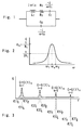
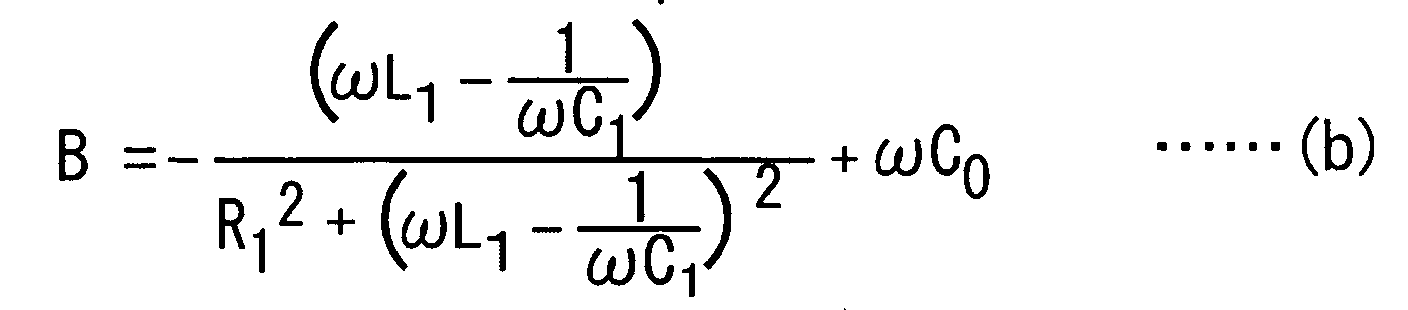
- the conductance G and the susceptance B can be expressed by the following Equations (a) and (b), with the motional resistance R 1 , the motional capacitance C 1 , the motional inductance L 1 and the static capacitance C 0 of the equivalent circuit in FIG. 1.
- G R 1 R 1 2 + ⁇ L 1 - 1 ⁇ C 1 2
- the value of the conductance G for the resonant state is expressed by G s , and taking half that value as the half-value conductance G s /2 and taking the angular frequency at which the half-value conductance G s /2 is given as the half-value angular frequency, there are two different half-value angular frequencies, namely a first half-value angular frequency ⁇ 1 that is lower than the resonance frequency f s and a second half-value angular frequency ⁇ 2 that is higher than the resonance frequency f s ( ⁇ 1 ⁇ ⁇ 2 ).
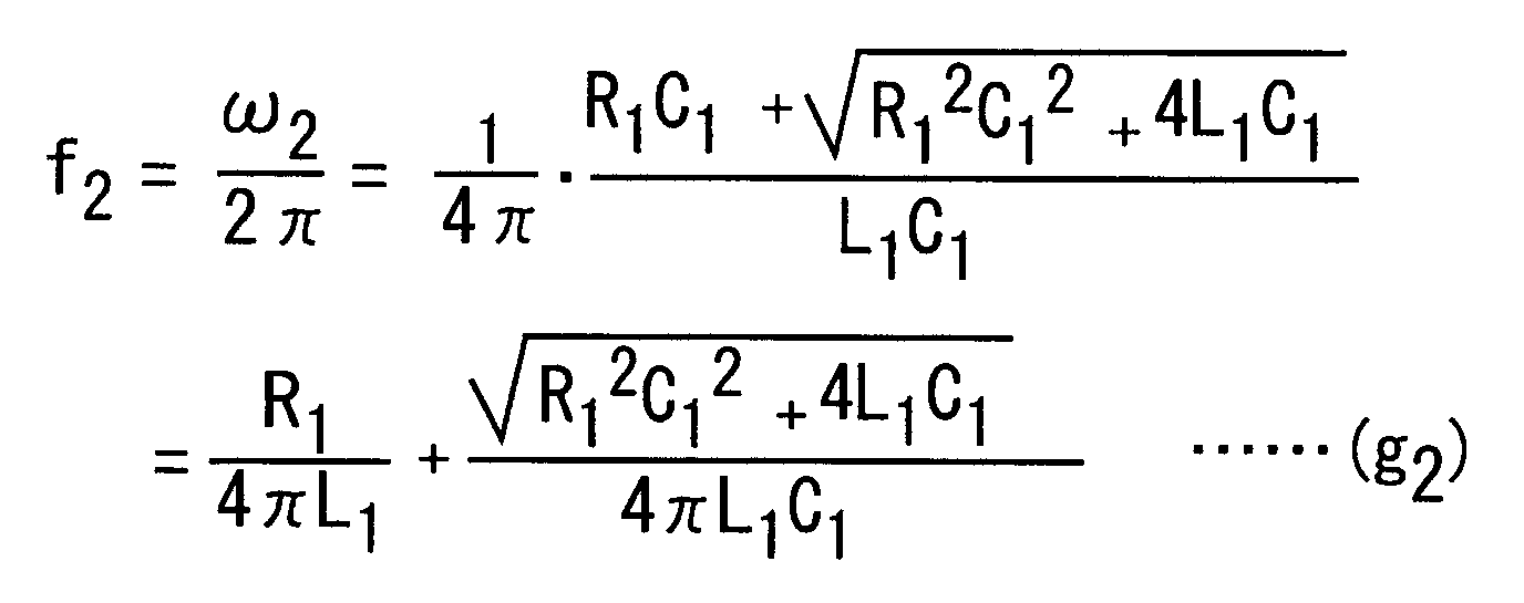
- the first and second half-value frequencies f 1 and f 2 corresponding to the first and the second half-value angular frequencies ⁇ 1 and ⁇ 2 can be expressed by the following Equations (g 1 ) and (g 2 ):
- ⁇ f 1 - ⁇ R 1 4 ⁇ L 1 + R 1 ⁇ ⁇ L 1 4 ⁇ L 1 2 + ⁇ f s (i 12 )
- ⁇ f 2 - ⁇ R 1 4 ⁇ L 1 + R 1 ⁇ ⁇ L 1 4 ⁇ L 1 2 + ⁇ f s (i 22 )
- ⁇ f 1 - ⁇ R 1 4 ⁇ L 1 + ⁇ f s (1 - R 1 8 ⁇ L 1 f s ) (i 13 )
- ⁇ f 2 - ⁇ R 1 4 ⁇ L 1 + ⁇ f s (1 + R 1 8 ⁇ L 1 f s ) (i 23 )
- Equation (i 13 ) can be approximated to the following Equation (j 1 ).
- Equation (i 22 ) can be approximated to the following Equation (j 2 ).
- ⁇ f 1 - ⁇ R 1 4 ⁇ L 1 + ⁇ f s (j 1 )
- ⁇ f 2 - ⁇ R 1 4 ⁇ L 1 + ⁇ f s (j 2 )
- Equation (j 1 ) the first term in Equation (j 1 ) is doubled, but in Equation (j 2 ) the first term is cancelled by the second term of Equation (k), and in Equation (l 2 ), the term including the infinitesimal change ⁇ R 1 of the motional resistance R 1 is cancelled, and only the term with the infinitesimal change ⁇ m of the mass m as the variable remains.
- the term for the influence of the viscosity changes is cancelled, and the equation expresses the frequency change due to only the mass load.
- the value of the conductance G in the resonant state changes, so that when measuring the second half-value frequency f 2 , the conductance G s of the resonant state is measured immediately before measuring the second half-value frequency f 2 , and the half-value conductance G s /2 is derived from this value, and the second half-value frequency f 2 can be determined from the greater frequency of the frequencies at which the half-value conductance G s /2 is given.
- the frequency changes excluding the mass effect that is, the frequency changes due to the viscosity effect are determined.
- Equation (l 2 ) expresses the frequency change due to the mass effect
- Equation (k) is the change in which the frequency change due to the mass effect and the frequency change due to the viscosity effect have been added, so that the frequency change due to the viscosity effect can be determined by subtracting Equation (1) from Equation (k).
- Equation (l 2 ) when Equation (l 2 ) is subtracted from Equation (k) to determine
- Equation (p) Equation (m) can be determined from Equations (l 1 ) and (l 2 ).
- the resonance frequency taking h into account is expressed as f (h) s
- the first and second half-value frequencies taking h into account are expressed as f(h) 1 and f(h) 2
- h is set to odd numbers (1, 3, 5, ...)
- the half-value conductance G(h) s /2 which is the half value of the local maxima G(h) s of conductance corresponding to the value h, is obtained.
- the first and second half-value frequencies f(h) 1 and f(h) 2 are obtained by the half-value conductance G(h) s /2.
- the frequency change ⁇ f(h) v due to the viscosity effect under consideration of h can be determined from, among others, the frequency change ⁇ f(h) s of the resonance frequency f(h) s and the frequency change ⁇ f(h) D of the difference f(h) D between the first and second half-value frequencies f(h) 1 and f(h) 2 .
- the first embodiment of the present invention is an analysis method including immersing a piezoelectric resonator having a crystal plate and first and second electrodes formed on the two sides of the crystal plate in a liquid, applying an AC signal to the first and second electrodes, and determining a mass change of the piezoelectric resonator from a relation between a frequency of the AC signal and an electric property of the piezoelectric resonator, wherein a first and second half value frequencies are frequency which give a half-value conductance and the half-value conductance is a half of conductance under series resonance state of the piezoelectric resonator, wherein the mass change of the piezoelectric resonator is determined by the change of the second half-value frequency which is close to the resonance frequency giving the series resonance state, and larger than the resonance frequency.
- the first embodiment of the present invention is the analysis method, wherein an AC signal of a frequency range that is anticipated to include the second half-value frequency is consecutively input to the piezoelectric resonator, and the mass change of the piezoelectric resonator over time is determined.
- the first embodiment of the present invention is the analysis method, wherein an initial value of the second half-value frequency is determined before the sample is given into the liquid, and the mass change of the piezoelectric resonator is determined from the fluctuation amount with respect to this initial value of the second half-value frequency.
- the first embodiment of the present invention is the analysis method, wherein an extremum value of the conductance of the piezoelectric resonator is measured, and the second half-value frequency is determined from the extremum.
- the first embodiment of the present invention is the analysis method, wherein the extremum value is a maximum value of the conductance of the piezoelectric resonator.
- the first embodiment of the present invention is the analysis method, wherein the second half-value frequency is determined from the resonance frequency of the piezoelectric resonator and a constant of an equivalent circuit of the piezoelectric resonator.
- the second embodiment of the present invention is an analysis method comprising, Immersing an excitable piezoelectric resonator in a liquid, and Applying an AC signal to the piezoelectric resonator, wherein a viscosity change of the liquid is determined from at least two frequencies of three frequencies including a resonance frequency that puts the piezoelectric resonator into a series resonance state, and first and second half-value frequencies obtaining a half-value conductance which is half conductance under the series resonance state of the piezoelectric resonator.
- the second embodiment of the present invention is the analysis method, wherein the AC signal is repeatedly input to the piezoelectric resonator at a frequency range that is anticipated to include the resonance frequency, a frequency change of the difference of the two frequencies is determined over time, and the viscosity change is determined from the frequency change of the difference of the two frequencies.
- the second embodiment of the present invention is the analysis method, wherein the piezoelectric resonator has a crystal plate and first and second electrodes formed on the two sides of the crystal plate and the AC signal is applied between the first and the second electrode.
- the second embodiment of the present invention is the analysis method, wherein a frequency change due to influence of a mass change of the piezoelectric resonator is determined using the second half-value frequency, which is the greater one of the first and second half-value frequencies.
- the second embodiment of the present invention is the analysis method, wherein a relation between conductance of the piezoelectric resonator and frequency is measured, and at least two of the three frequencies are determined.
- the second embodiment of the present invention is the analysis method, wherein the maximum of the conductance is used.
- the present invention is the analysis method, wherein the resonance frequency of the piezoelectric resonator and a constant of its equivalent circuit are used.
- FIG. 4A is a cross-sectional view of a measurement cell 2 of an embodiment of the present invention
- FIG. 4B is a plan view of a quartz resonator 3 of this measurement cell
- FIG. 4C is a cross-sectional view thereof.
- the piezoelectric resonator 3 has a crystal plate 30, and a first and a second electrode 31 and 32 are arranged on the top surface and the rear surface side of this crystal plate 30, respectively.
- the crystal plate 30 is made by forming a crystal, such as a quartz crystal for example, into disk shape, and the first and second electrodes 31 and 32 are made by patterning metal films into a predetermined shape. A part of the first electrode 31 is wrapped around to the rear side of the crystal plate 30.
- the first and second electrodes 31 and 32 are connected to ends of first and second springs 24 and 25 at the locations on the rear surface of the crystal plate 30.
- the other ends of the first and second springs 24 and 25 are connected to first and second terminal pins 26 and 27.
- the first and second springs 24 and 25 are made of metal, and the first and second electrodes 31 and 32 are electrically connected to the first and second terminal pins 26 and 27 via the first and second springs 24 and 25.
- Reference numeral 23 denotes an insulating base, and the first and second connection pins 26 and 27 are fixed to this base 23 by glass seals 28.
- the cell 2 has a cell body 20 made by, for example, acrylic resin formed into a tubular shape.
- a flange portion 21 is formed at a location slightly above the bottom of the cell body 20, a flange portion 21 is formed.
- the piezoelectric resonator 3 is inserted into the cell body 20 from the bottom side of the cell body 20, and the outer peripheral portion of the piezoelectric resonator 3 is in contact with the flange portion 21.
- An adhesive is arranged at the portion where the piezoelectric resonator 3 and the flange portion 21 are in contact, and while the outer periphery of the piezoelectric resonator 3 is pressed against the flange portion 21 by the first and second springs 24 and 25; the base 23 is fixed to the bottom face of the cell body 20; and the piezoelectric resonator 3 is fixed to the flange portion 21 by the adhesive.
- a fluid-tight container portion 20a that is shaped like a tubular vessel with a bottom is constituted with the piezoelectric resonator 3 as a bottom surface, and the cell body 20 as the upper portion.
- the first and second terminal pins 26 and 27 are drawn out of the cell body 20 from the bottom surface of the base 23, and by connecting the first and second terminal pins 26 and 27 to an external circuit of the measurement equipment or the like, the first and second electrodes 31 and 32 are connected to this external circuit.
- the first electrode 31 is arranged on the top surface side of the crystal plate 30, that is, at a location where it is exposed at the bottom surface of the container portion 20a, and a reaction film 33 is disposed on the surface of this first electrode 31.
- This reaction film 33 is made of a material that reacts with a specific component to be measured, or adsorbs this specific component.
- the cell 2 is arranged on a platform 29, and a liquid, which is a solvent in which the specific component to be measured is dissolved, or a liquid in which the specific component is dispersed, but which does not yet contain the specific component, is filled into the container portion 20a.
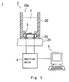
- Reference numeral 7 in FIG. 5 denotes this liquid, and in this state, the reaction film 33 is in contact with the liquid 7.
- the second electrode 32 positioned on the opposite site of the first electrode 31 is not in contact with the liquid 7. Consequently, in this example, N in the above Equations (1) to (10) is 1.
- Reference numeral 1 in FIG. 5 denotes the measurement apparatus, which includes the above-mentioned cell 2, an analytical device 4 having such as a network analyzer or an impedance analyzer, and a control device 5 that controls the analytical device 4 and calculates the measurement value.
- the cell 2 is connected to the analytical device 4, which outputs alternating current signal of the desired frequency to the cell 2, and the conductance G of the cell 2 at this frequency can be measured.
- control device 5 controls the operation of the analytical device 4, and the analytical device 4 changes the frequency of the signal that is output to the cell 2, correlates the frequency with the measurement result, and stores them together with the calculation result.
- the frequency is changed within a predetermined range including the resonance frequency f s , and if the relation between the frequency and the conductance G is measured, then the conductance G takes on an extremum at the resonance frequency.
- the measurement value of the resonance frequency f s before adding the sample is the initial value of the resonance frequency f s .
- a signal is applied to the cell 2 whose frequency is varied over a predetermined range that includes the initial value of the resonance frequency f s and the initial value of the second half-value frequency f 2 , and then, the conductance G of the cell 2 is measured.
- the maximum value of the conductance G is measured in intervals of one second while changing the frequency of the AC signal at the predetermined range.
- the second half-value frequency f 2 is obtained by the half-value conductance which is 1/2 of conductance. After adding the sample, this procedure is repeated in constant intervals (for example, every second).
- the concentration of the specific component in the liquid to be measured can be determined.
- FIG. 6 is a graph showing the frequency difference ⁇ f and a time for the case that the piezoelectric resonator is immersed in water, and the water temperature is increased in steps of 5° from 20°C to 35°C.
- a 1 denotes a curve showing the change of the frequency difference ⁇ f of the second half-value frequency f 2
- a 2 denotes a curve showing the change of the frequency difference ⁇ f of the resonance frequency f s .
- the viscosity of the liquid decreases, so that the change in the frequency difference ⁇ f of the resonance frequency f s is large.
- the change of the frequency difference ⁇ f of the second half-value frequency f 2 is zero (the slight change that can be seen is due to variations of the properties of the quartz resonator as the temperature is changed).
- FIG. 7 is a graph showing the changes over time of the frequency difference ⁇ f in the presence of both the mass effect and the viscosity effect.
- b 1 indicates the fluctuations of the frequency difference ⁇ f of the second half-value frequency f 2
- b 2 indicates the fluctuations of the frequency difference ⁇ f of the resonance frequency f s .
- the time at which the piezoelectric resonator 3 was immersed in the buffer solution is taken as the measurement start time, and a first sample (avidin) was added at a time of 300 seconds after the measurement start time, then a second sample (liquid mixture of glycerol and avidin (with the same concentration of avidin as in the first sample)) was added at a time of 1200 seconds after the measurement start time, and after 2400 seconds had passed, a third sample (only glycerol, same amount as for the second sample) was added.
- the frequency differences ⁇ f change due to the adherence of avidin, but it changes with a constant slope for the second half-value difference f 2 , whereas for the frequency difference ⁇ f of the resonance frequency f s , the frequency is decreased greatly by the viscosity effect due to the glycerol.
- the conductance G for the series resonance state is measured, and the second half-value frequency f 2 is determined from 1/2 that value. It is also possible not to measure the conductance G for the series resonance state and to calculate the second half-value resonance f 2 using the measured value of the resonance frequency f s and the constants R 1 , L 1 and C 1 of the equivalent circuit.
- the second half-value frequency f 2 can be calculated from Equation (i 1 ) without measuring the conductance G.
- the present invention is not limited to actually measuring the conductance G to determine the second half-value frequency f 2 , but also includes the case that values other than the conductance G are measured to obtain the second half-value frequency f 2 .
- the present invention is not susceptible to the modification effect by the remperature change or using a sample whose viscosity is different from that of the buffer solution, so that an accurate measurement becomes possible.
- the present invention is very effective for the testing of, for example, blood, which has high viscosity, or for testing for germs in food.
- the stabilization time until the temperature of the buffer has reached the temperature set with the apparatus can be shortened, thus increasing the throughput.
- a frequency range including the resonance frequency f s of the cell 2, and the first and second half-value frequencies f 1 and f 2 is set beforehand, the frequency is changed within this range.
- the value of the conductance G is measured, and the frequency f applied to the cell 2 and the value of the conductance G at that frequency f are stored in correlation.
- the frequency f at which the maximum value G max of the conductance G is given within that frequency range will be the resonance frequency f s .
- the first and second half-value frequencies f 1 and f 2 at which 1/2 of the maximum value G max of the conductance G (that is, the half-value conductance G s /2) is given are determined.
- the measured values of resonance frequency f s and the first and second half-value frequencies f 1 and f 2 before adding the sample are the initial values.
- a signal whose frequency range is anticipated to include the resonance frequency f s and the first and second half-value frequencies is applied to the cell 2, and similar to when determining the initial value, the maximum value G max of the conductance G is determined, and the first and second half-value frequencies f 1 and f 2 are determined from the half-value conductance G s /2.
- the value obtained by subtracting the initial value from the measured value of the frequency after adding the sample is the frequency change at each measurement time. Consequently, utilizing the frequency change ⁇ f s of the resonance frequency f s and the frequency change ⁇ f 2 of the second half-value frequency f 2 , the frequency change ⁇ f v due to the viscosity effect can be determined from Equation (m), or utilizing the frequency changes ⁇ f 1 and ⁇ f 2 of the first and second half-value frequencies f 1 and f 2 , the frequency change ⁇ f v due to the viscosity effect can be determined from Equation (p).
- the frequency change due to the mass effect can be determined from the frequency change ⁇ f 2 of the second half-value frequency f 2 . From the frequency change due to the mass effect, the concentration of the specific component in the liquid to be measured can be known.
- the cell 2 had a reaction film 33 and the specific component to be measured in the sample was reacted or adsorbed to the reaction film 33, but if it is not necessary to determine the frequency changes due to the mass effect (for example, if the viscosity changes of the liquid for temperature fluctuations are determined), then the reaction film 33 of the cell 2 is not necessary; and it is possible to use a cell without a reaction film.
- the relation between the conductance G and the frequency f was measured for the series resonance state, and the first and second half-value frequencies f 1 and f 2 were determined from the value of the half-value conductance G s /2, which is 1/2 the maximum value G max , but it is also possible to calculate the first and second half-value frequencies f 1 and f 2 using the measured value of the resonance frequency f s and the constants R 1 , L 1 and C 1 of the equivalent circuit, without measuring the conductance G in the series resonance state.
- the first and second half-value frequencies f 1 and f 2 can be calculated from Equations (i) without measuring the conductance G. Therefore, it is possible to determine the frequency change ⁇ f v due to the viscosity effect without measuring the conductance G.
- the frequency changes ⁇ f v due to the viscosity effect can be determined from the resonance frequency f v and the Q value (or the D value).
- the present invention is not limited to actually measuring the conductance G to determine the resonance frequency f s or the first or second half-value frequency f 1 or f 2 .
- the frequency changes ⁇ f v due to the viscosity effect were determined based on Equation (m) or Equation (n) from a combination of the first half-value frequency f 1 and the resonance frequency f v or a combination of the first and second half-value frequencies f 1 and f 2 , but the first term in Equation (k) and the second term in Equation (l 1 ) can be cancelled, so that it is possible to determine the frequency changes ⁇ f v due to the viscosity effect also by combining the resonance frequency f s and the first half-value frequency f 1 .
- the frequency changes due to the mass effect and the frequency changes due to the viscosity effect can be determined together, so that detailed analysis of the sample becomes possible. Consequently, the present invention is very effective for testing, for example, blood, which has high viscosity, or for testing for germs in food.
Landscapes
- Physics & Mathematics (AREA)
- Chemical & Material Sciences (AREA)
- General Health & Medical Sciences (AREA)
- General Physics & Mathematics (AREA)
- Health & Medical Sciences (AREA)
- Life Sciences & Earth Sciences (AREA)
- Analytical Chemistry (AREA)
- Biochemistry (AREA)
- Pathology (AREA)
- Immunology (AREA)
- Electrochemistry (AREA)
- Chemical Kinetics & Catalysis (AREA)
- Acoustics & Sound (AREA)
- Piezo-Electric Or Mechanical Vibrators, Or Delay Or Filter Circuits (AREA)
- Investigating Or Analyzing Materials By The Use Of Electric Means (AREA)
- Measurement Of Mechanical Vibrations Or Ultrasonic Waves (AREA)
Abstract
Description
The references are mentioned below.

| Δfs | Series resonant frequency change |
| f0 | Fundamental frequency |
| ρQ | Density of quartz (2. 648g/cm2) |
| µQ | Elastic constant of quartz piezoelectrically stiffened (2. 947 × 1011g/cm · S2) |
| Δm | Mass change |
| A | First and second electrode area |
| h | Harmonic number (h=1, 3, 5, ···) |
| L1 | Motional inductance |
| ΔR1 | Motional resistance change |

| h | Harmonic number (h=1, 3, 5, ···) |
| f0 | Fundamental frequency |
| ρ1 | Density of liquid |
| η1 | Viscosity of liquid |
| ρQ | Density of quartz (2. 648g/cm2) |
| µQ | Elastic constant of quartz piezoelectrically stiffened (2. 947 × 1011g/cm · S2) |

| h | Harmonic number (h=1, 3, 5, ···) |
| f0 | Fundamental frequency |
| ρQ | Density of quartz (2. 648g/cm2) |
| µQ | Elastic constant of quartz piezoelectrically stiffened (2. 947 × 1011g/cm · S2) |
| Δm | Mass change |
| A | First and second electrode area |
Claims (13)
- An analysis method, comprising the steps of;wherein a first and second half value frequencies are frequencies which give a half-value conductance and the half-value conductance is a half of conductance under a series resonance state of the piezoelectric resonator,immersing a piezoelectric resonator having a crystal plate and first and second electrodes formed on two sides of the crystal plate in a liquid;applying an AC signal to the first and second electrodes; anddetermining a mass change of the piezoelectric resonator from a relation between a frequency of the AC signal and an electric property of the piezoelectric resonator,
wherein the mass change of the piezoelectric resonator is determined by the change of the second half-value frequency which is close to the resonance frequency giving the series resonance state, and larger than the resonance frequency. - The analysis method according to claim 1,
wherein an AC signal of a frequency range that is anticipated to include the second half-value frequency is consecutively input to the piezoelectric resonator, and the mass change of the piezoelectric resonator over time is determined. - The analysis method according to claim 1,
wherein an initial value of the second half-value frequency is determined before the sample is given into the liquid, and the mass change of the piezoelectric resonator is determined from the fluctuation amount with respect to this initial value of the second half-value frequency. - The analysis method according to claim 1,
wherein an extremum value of the conductance of the piezoelectric resonator is measured, and the second half-value frequency is determined from the extremum. - The analysis method according to claim 4,
wherein the extremum value is a maximum value of the conductance of the piezoelectric resonator. - The analysis method according to claim 1,
wherein the second half-value frequency is determined from the resonance frequency of the piezoelectric resonator and a constant of an equivalent circuit of the piezoelectric resonator. - An analysis method comprising the steps of;wherein a viscosity change of the liquid is determined from at least two frequencies of three frequencies including a resonance frequency that puts the piezoelectric resonator into a series resonance state, and first and second half-value frequencies obtaining a half-value conductance which is half conductance under the series resonance state of the piezoelectric resonator.immersing an excitable piezoelectric resonator in a liquid; andapplying an AC signal to the piezoelectric resonator,
- The analysis method according to claim 7,
wherein the AC signal is repeatedly input to the piezoelectric resonator at a frequency range that is anticipated to include the resonance frequency, a frequency change of the difference of the two frequencies is determined over time, and the viscosity change is determined from the frequency change of the difference of the two frequencies. - The analysis method according to claim 7,
wherein the piezoelectric resonator has a crystal plate and first and second electrodes formed on the two sides of the crystal plate; and
the AC signal is applied between the first and the second electrode. - The analysis method according to claim 9,
wherein a frequency change due to influence of a mass change of the piezoelectric resonator is determined using the second half-value frequency, which is the greater one of the first and second half-value frequencies. - The analysis method according to claim 7,
wherein a relation between conductance of the piezoelectric resonator and frequency is measured, and at least two of the three frequencies are determined. - The analysis method according to claim 11,
wherein the maximum of the conductance is used. - The analysis method according to claim 11,
wherein the resonance frequency of the piezoelectric resonator and a constant of its equivalent circuit are used.
Applications Claiming Priority (6)
| Application Number | Priority Date | Filing Date | Title |
|---|---|---|---|
| JP2002376087 | 2002-12-26 | ||
| JP2002376087 | 2002-12-26 | ||
| JP2003120370A JP4083621B2 (en) | 2003-04-24 | 2003-04-24 | Analysis method using vibrator |
| JP2003120335 | 2003-04-24 | ||
| JP2003120335A JP4009221B2 (en) | 2002-12-26 | 2003-04-24 | Analysis method using vibrator |
| JP2003120370 | 2003-04-24 |
Publications (3)
| Publication Number | Publication Date |
|---|---|
| EP1434047A2 true EP1434047A2 (en) | 2004-06-30 |
| EP1434047A3 EP1434047A3 (en) | 2005-01-05 |
| EP1434047B1 EP1434047B1 (en) | 2014-02-19 |
Family
ID=32475238
Family Applications (1)
| Application Number | Title | Priority Date | Filing Date |
|---|---|---|---|
| EP03029796.4A Expired - Lifetime EP1434047B1 (en) | 2002-12-26 | 2003-12-23 | Analysis method using piezoelectric resonator |
Country Status (2)
| Country | Link |
|---|---|
| US (2) | US7111500B2 (en) |
| EP (1) | EP1434047B1 (en) |
Cited By (4)
| Publication number | Priority date | Publication date | Assignee | Title |
|---|---|---|---|---|
| GB2461618A (en) * | 2008-07-10 | 2010-01-13 | Sekonic Corp | Measuring viscosity and/or elasticity of liquid |
| EP1898203A4 (en) * | 2005-06-30 | 2012-01-11 | Ulvac Inc | MEASURING METHOD AND INSTRUMENT EMPLOYING A CRYSTAL OSCILLATOR |
| CN103109175A (en) * | 2010-10-20 | 2013-05-15 | 株式会社爱发科 | Method of measuring viscoelasticity coefficients of material and device for measuring viscoelasticity coefficients of material |
| EP2278298A4 (en) * | 2008-05-14 | 2017-08-30 | Ulvac, Inc. | Quartz oscillator and measurement method using same |
Families Citing this family (18)
| Publication number | Priority date | Publication date | Assignee | Title |
|---|---|---|---|---|
| US20030101819A1 (en) * | 2001-12-04 | 2003-06-05 | Mutz Mitchell W. | Acoustic assessment of fluids in a plurality of reservoirs |
| AT413767B (en) * | 2003-03-20 | 2006-05-15 | Avl List Gmbh | METHOD, DEVICE AND SENSOR FOR DETERMINING THE REDOX CONDITION OF A CATALYST MATERIAL |
| CN101084427B (en) * | 2004-12-15 | 2011-07-20 | 日本电波工业株式会社 | Crystal sensor and sensing device |
| US7568377B2 (en) * | 2005-07-28 | 2009-08-04 | University Of South Florida | High frequency thickness shear mode acoustic wave sensor for gas and organic vapor detection |
| EP1854992B1 (en) * | 2006-05-09 | 2010-08-11 | Continental Automotive GmbH | Fuel injection system and method of manufacture |
| US8092384B2 (en) * | 2006-09-28 | 2012-01-10 | Tyco Healthcare Group Lp | System and method for continuous detection of an analyte in bloodstream |
| US7844401B2 (en) * | 2007-01-19 | 2010-11-30 | Baker Hushes Incorpated | System and method for determining producibility of a formation using flexural mechanical resonator measurements |
| US7694552B2 (en) * | 2007-02-12 | 2010-04-13 | The Board Of Trustees Of The Leland Stanford Junior University | High quality factor resonators for liquid immersion biological and chemical sensors |
| DE102008026008B4 (en) * | 2007-05-29 | 2011-04-28 | Leibniz-Institut für Festkörper- und Werkstoffforschung e.V. | Method for determining the viscosity and elasticity of viscoelastic media |
| US7802466B2 (en) * | 2007-11-28 | 2010-09-28 | Sierra Sensors Gmbh | Oscillating sensor and fluid sample analysis using an oscillating sensor |
| DE102008026009B4 (en) * | 2008-05-29 | 2010-09-16 | Leibniz-Institut Für Festkörper- Und Werkstoffforschung Dresden E.V. | Method for determining the viscosity and elasticity of viscoelastic media |
| ES2333088B2 (en) | 2009-06-23 | 2011-02-07 | Universidad Politecnica De Valencia | METHOD AND DEVICE OF NANOGRAVIMETRY IN FLUID MEDIA BASED ON PIEZOELECTRIC RESONATORS. |
| US9146187B2 (en) | 2010-03-16 | 2015-09-29 | Ulvac, Inc. | Viscoelasticity measuring method and viscoelasticity measuring apparatus |
| DK2630479T3 (en) | 2010-10-20 | 2020-07-20 | Qorvo Us Inc | DEVICE AND METHOD FOR MEASURING BINDING KINETICS AND CONCENTRATION WITH A RESONANCE SENSOR |
| CN102507653B (en) * | 2011-10-11 | 2014-04-16 | 广东风华高新科技股份有限公司 | Annular piezoresistor microcrack detection device and method |
| RU2568331C1 (en) * | 2014-04-29 | 2015-11-20 | Российская Федерация, от имени которой выступает Министерство обороны Российской Федерации | Device determining leaks of explosive liquids based on piezoelectric sensor |
| CN104833610B (en) * | 2015-04-23 | 2017-07-28 | 电子科技大学 | A kind of liquid character measuring method based on piezoelectric sound wave resonant transducer |
| AT523957A1 (en) * | 2020-06-24 | 2022-01-15 | Usepat Gmbh | Device and method for preparing and/or analyzing a measurement fluid for measurement in a measurement device |
Family Cites Families (13)
| Publication number | Priority date | Publication date | Assignee | Title |
|---|---|---|---|---|
| US3564463A (en) * | 1966-04-11 | 1971-02-16 | Bell Telephone Labor Inc | Monolithic piezoelectric filter having mass loaded electrodes for resonation regions acoustically coupled together |
| US4741200A (en) * | 1986-07-11 | 1988-05-03 | Ford Motor Company | Method and apparatus for measuring viscosity in a liquid utilizing a piezoelectric sensor |
| US4721874A (en) * | 1986-10-06 | 1988-01-26 | Emmert Sans W | Apparatus and method for determining the viscosity of a fluid sample |
| US4862384A (en) * | 1987-08-03 | 1989-08-29 | Rockwell International Corporation | Method of measuring the dynamic viscosity of a viscous fluid utilizing acoustic transducer |
| US5067344A (en) * | 1989-05-08 | 1991-11-26 | Natonal Metal And Refining Company, Inc. | Vibratory viscometer transducer with isolation support for inline viscosity sensor |
| JP3041361B2 (en) | 1990-04-17 | 2000-05-15 | セイコーインスツルメンツ株式会社 | Reaction measurement device |
| GB9018661D0 (en) * | 1990-08-24 | 1990-10-10 | British Aerospace | Multipole vibrating surface gyroscope |
| US5201215A (en) * | 1991-10-17 | 1993-04-13 | The United States Of America As Represented By The United States Department Of Energy | Method for simultaneous measurement of mass loading and fluid property changes using a quartz crystal microbalance |
| US6494079B1 (en) * | 2001-03-07 | 2002-12-17 | Symyx Technologies, Inc. | Method and apparatus for characterizing materials by using a mechanical resonator |
| US6260408B1 (en) * | 1998-05-13 | 2001-07-17 | The United States Of America As Represented By The Secretary Of The Army | Techniques for sensing the properties of fluids with a resonator assembly |
| US6334356B1 (en) * | 1998-10-15 | 2002-01-01 | Kyoto Electronics Manufacturing Company, Limited | Method for deciding the viscosity in the density measurement |
| JP2002148295A (en) | 2000-11-10 | 2002-05-22 | Ulvac Japan Ltd | Frequency measuring method, frequency measuring device and analyzer |
| JP2002156368A (en) | 2000-11-17 | 2002-05-31 | Ulvac Japan Ltd | Characteristic measuring device and analyzing device |
-
2003
- 2003-12-19 US US10/739,397 patent/US7111500B2/en not_active Expired - Lifetime
- 2003-12-23 EP EP03029796.4A patent/EP1434047B1/en not_active Expired - Lifetime
-
2006
- 2006-08-11 US US11/502,404 patent/US7201041B2/en not_active Expired - Lifetime
Non-Patent Citations (1)
| Title |
|---|
| None |
Cited By (6)
| Publication number | Priority date | Publication date | Assignee | Title |
|---|---|---|---|---|
| EP1898203A4 (en) * | 2005-06-30 | 2012-01-11 | Ulvac Inc | MEASURING METHOD AND INSTRUMENT EMPLOYING A CRYSTAL OSCILLATOR |
| EP2278298A4 (en) * | 2008-05-14 | 2017-08-30 | Ulvac, Inc. | Quartz oscillator and measurement method using same |
| GB2461618A (en) * | 2008-07-10 | 2010-01-13 | Sekonic Corp | Measuring viscosity and/or elasticity of liquid |
| GB2461618B (en) * | 2008-07-10 | 2012-07-04 | Sekonic Corp | Method for measuring viscosity and elasticity of liquid |
| CN103109175A (en) * | 2010-10-20 | 2013-05-15 | 株式会社爱发科 | Method of measuring viscoelasticity coefficients of material and device for measuring viscoelasticity coefficients of material |
| CN103109175B (en) * | 2010-10-20 | 2015-07-08 | 株式会社爱发科 | Method of measuring viscoelasticity coefficients of material and device for measuring viscoelasticity coefficients of material |
Also Published As
| Publication number | Publication date |
|---|---|
| EP1434047A3 (en) | 2005-01-05 |
| EP1434047B1 (en) | 2014-02-19 |
| US20060272396A1 (en) | 2006-12-07 |
| US7111500B2 (en) | 2006-09-26 |
| US7201041B2 (en) | 2007-04-10 |
| US20040150428A1 (en) | 2004-08-05 |
Similar Documents
| Publication | Publication Date | Title |
|---|---|---|
| EP1434047B1 (en) | Analysis method using piezoelectric resonator | |
| Buck et al. | Piezoelectric chemical sensors | |
| EP0943091B2 (en) | Method and apparatus for characterizing materials by using a mechanical resonator | |
| US5455475A (en) | Piezoelectric resonant sensor using the acoustoelectric effect | |
| JP4083621B2 (en) | Analysis method using vibrator | |
| Arnau et al. | An extended Butterworth Van Dyke model for quartz crystal microbalance applications in viscoelastic fluid media | |
| KR20120103542A (en) | Method and device for nanogravimetry in fluid media using piezoelectric resonators | |
| JP4387896B2 (en) | QCM sensor and measurement method using QCM sensor | |
| US7398685B2 (en) | Measuring method using surface acoustic wave device, and surface acoustic wave device and biosensor device | |
| JP5379909B2 (en) | Viscoelasticity measuring method and viscoelasticity measuring device | |
| Itoh et al. | A frequency of the quartz crystal microbalance (QCM) that is not affected by the viscosity of a liquid | |
| JP4669749B2 (en) | Measuring method and measuring apparatus using crystal resonator | |
| JP4009221B2 (en) | Analysis method using vibrator | |
| US7331232B2 (en) | Measurement method and biosensor apparatus using resonator | |
| JP2007010519A5 (en) | ||
| Zhou et al. | Impedance analysis for the investigation of the behaviors of piezoelectric quartz crystal in the liquid at harmonic resonance | |
| JPH02226044A (en) | Specimen cell | |
| Zhang et al. | Mass effects of quartz resonant sensors with different surface microstructures in liquids | |
| US7493798B2 (en) | Sensor for detecting the adulteration and quality of fluids | |
| JP3911191B2 (en) | Analysis method | |
| KR102258668B1 (en) | How to verify the resonator | |
| McGann et al. | Acoustic mode behavior in lateral field excited sensors | |
| Zhang et al. | Miniature high-frequency longitudinal wave mass sensors in liquid | |
| Schaefer et al. | Single board impedance analyzer and transient analysis of QCR sensor response | |
| Zhou et al. | A defect coefficient—new insight into the responses of piezoelectric quartz crystal in gaseous and liquid phases |
Legal Events
| Date | Code | Title | Description |
|---|---|---|---|
| PUAI | Public reference made under article 153(3) epc to a published international application that has entered the european phase |
Free format text: ORIGINAL CODE: 0009012 |
|
| AK | Designated contracting states |
Kind code of ref document: A2 Designated state(s): AT BE BG CH CY CZ DE DK EE ES FI FR GB GR HU IE IT LI LU MC NL PT RO SE SI SK TR |
|
| AX | Request for extension of the european patent |
Extension state: AL LT LV MK |
|
| PUAL | Search report despatched |
Free format text: ORIGINAL CODE: 0009013 |
|
| AK | Designated contracting states |
Kind code of ref document: A3 Designated state(s): AT BE BG CH CY CZ DE DK EE ES FI FR GB GR HU IE IT LI LU MC NL PT RO SE SI SK TR |
|
| AX | Request for extension of the european patent |
Extension state: AL LT LV MK |
|
| 17P | Request for examination filed |
Effective date: 20050330 |
|
| AKX | Designation fees paid |
Designated state(s): DE FR GB SE |
|
| 17Q | First examination report despatched |
Effective date: 20090507 |
|
| GRAP | Despatch of communication of intention to grant a patent |
Free format text: ORIGINAL CODE: EPIDOSNIGR1 |
|
| RIC1 | Information provided on ipc code assigned before grant |
Ipc: G01N 27/02 20060101ALI20131001BHEP Ipc: G01N 29/036 20060101ALI20131001BHEP Ipc: G01N 27/00 20060101AFI20131001BHEP Ipc: G01N 27/12 20060101ALI20131001BHEP |
|
| INTG | Intention to grant announced |
Effective date: 20131016 |
|
| GRAS | Grant fee paid |
Free format text: ORIGINAL CODE: EPIDOSNIGR3 |
|
| GRAA | (expected) grant |
Free format text: ORIGINAL CODE: 0009210 |
|
| AK | Designated contracting states |
Kind code of ref document: B1 Designated state(s): DE FR GB SE |
|
| REG | Reference to a national code |
Ref country code: GB Ref legal event code: FG4D |
|
| REG | Reference to a national code |
Ref country code: SE Ref legal event code: TRGR |
|
| REG | Reference to a national code |
Ref country code: DE Ref legal event code: R096 Ref document number: 60345728 Country of ref document: DE Effective date: 20140327 |
|
| REG | Reference to a national code |
Ref country code: DE Ref legal event code: R097 Ref document number: 60345728 Country of ref document: DE |
|
| PLBE | No opposition filed within time limit |
Free format text: ORIGINAL CODE: 0009261 |
|
| STAA | Information on the status of an ep patent application or granted ep patent |
Free format text: STATUS: NO OPPOSITION FILED WITHIN TIME LIMIT |
|
| 26N | No opposition filed |
Effective date: 20141120 |
|
| REG | Reference to a national code |
Ref country code: DE Ref legal event code: R097 Ref document number: 60345728 Country of ref document: DE Effective date: 20141120 |
|
| REG | Reference to a national code |
Ref country code: FR Ref legal event code: PLFP Year of fee payment: 13 |
|
| REG | Reference to a national code |
Ref country code: FR Ref legal event code: PLFP Year of fee payment: 14 |
|
| REG | Reference to a national code |
Ref country code: FR Ref legal event code: PLFP Year of fee payment: 15 |
|
| PGFP | Annual fee paid to national office [announced via postgrant information from national office to epo] |
Ref country code: SE Payment date: 20221222 Year of fee payment: 20 Ref country code: GB Payment date: 20221222 Year of fee payment: 20 Ref country code: FR Payment date: 20221222 Year of fee payment: 20 Ref country code: DE Payment date: 20221213 Year of fee payment: 20 |
|
| REG | Reference to a national code |
Ref country code: DE Ref legal event code: R071 Ref document number: 60345728 Country of ref document: DE |
|
| REG | Reference to a national code |
Ref country code: GB Ref legal event code: PE20 Expiry date: 20231222 |
|
| PG25 | Lapsed in a contracting state [announced via postgrant information from national office to epo] |
Ref country code: GB Free format text: LAPSE BECAUSE OF EXPIRATION OF PROTECTION Effective date: 20231222 |
|
| REG | Reference to a national code |
Ref country code: SE Ref legal event code: EUG |
|
| PG25 | Lapsed in a contracting state [announced via postgrant information from national office to epo] |
Ref country code: GB Free format text: LAPSE BECAUSE OF EXPIRATION OF PROTECTION Effective date: 20231222 |