EP1433982B1 - Closed loop control of shifting clutch actuators in an automatic speed change transmission - Google Patents
Closed loop control of shifting clutch actuators in an automatic speed change transmission Download PDFInfo
- Publication number
- EP1433982B1 EP1433982B1 EP03028192A EP03028192A EP1433982B1 EP 1433982 B1 EP1433982 B1 EP 1433982B1 EP 03028192 A EP03028192 A EP 03028192A EP 03028192 A EP03028192 A EP 03028192A EP 1433982 B1 EP1433982 B1 EP 1433982B1
- Authority
- EP
- European Patent Office
- Prior art keywords
- pressure
- valve
- transmission
- clutch
- actuators
- Prior art date
- Legal status (The legal status is an assumption and is not a legal conclusion. Google has not performed a legal analysis and makes no representation as to the accuracy of the status listed.)
- Expired - Lifetime
Links
- 230000005540 biological transmission Effects 0.000 title claims abstract description 49
- 238000000034 method Methods 0.000 claims abstract description 11
- 239000012530 fluid Substances 0.000 claims description 27
- 230000000694 effects Effects 0.000 claims 2
- 230000003213 activating effect Effects 0.000 claims 1
- 238000009795 derivation Methods 0.000 claims 1
- 238000010586 diagram Methods 0.000 description 8
- 238000004891 communication Methods 0.000 description 3
- 238000004519 manufacturing process Methods 0.000 description 2
- 230000000712 assembly Effects 0.000 description 1
- 238000000429 assembly Methods 0.000 description 1
- 238000011088 calibration curve Methods 0.000 description 1
- 238000012790 confirmation Methods 0.000 description 1
- 238000011109 contamination Methods 0.000 description 1
- 230000001419 dependent effect Effects 0.000 description 1
- 230000004048 modification Effects 0.000 description 1
- 238000012986 modification Methods 0.000 description 1
- 230000000750 progressive effect Effects 0.000 description 1
Images


Classifications
-
- B—PERFORMING OPERATIONS; TRANSPORTING
- B60—VEHICLES IN GENERAL
- B60W—CONJOINT CONTROL OF VEHICLE SUB-UNITS OF DIFFERENT TYPE OR DIFFERENT FUNCTION; CONTROL SYSTEMS SPECIALLY ADAPTED FOR HYBRID VEHICLES; ROAD VEHICLE DRIVE CONTROL SYSTEMS FOR PURPOSES NOT RELATED TO THE CONTROL OF A PARTICULAR SUB-UNIT
- B60W10/00—Conjoint control of vehicle sub-units of different type or different function
- B60W10/18—Conjoint control of vehicle sub-units of different type or different function including control of braking systems
-
- F—MECHANICAL ENGINEERING; LIGHTING; HEATING; WEAPONS; BLASTING
- F16—ENGINEERING ELEMENTS AND UNITS; GENERAL MEASURES FOR PRODUCING AND MAINTAINING EFFECTIVE FUNCTIONING OF MACHINES OR INSTALLATIONS; THERMAL INSULATION IN GENERAL
- F16H—GEARING
- F16H61/00—Control functions within control units of change-speed- or reversing-gearings for conveying rotary motion ; Control of exclusively fluid gearing, friction gearing, gearings with endless flexible members or other particular types of gearing
- F16H61/02—Control functions within control units of change-speed- or reversing-gearings for conveying rotary motion ; Control of exclusively fluid gearing, friction gearing, gearings with endless flexible members or other particular types of gearing characterised by the signals used
- F16H61/0202—Control functions within control units of change-speed- or reversing-gearings for conveying rotary motion ; Control of exclusively fluid gearing, friction gearing, gearings with endless flexible members or other particular types of gearing characterised by the signals used the signals being electric
- F16H61/0204—Control functions within control units of change-speed- or reversing-gearings for conveying rotary motion ; Control of exclusively fluid gearing, friction gearing, gearings with endless flexible members or other particular types of gearing characterised by the signals used the signals being electric for gearshift control, e.g. control functions for performing shifting or generation of shift signal
- F16H61/0206—Layout of electro-hydraulic control circuits, e.g. arrangement of valves
-
- B—PERFORMING OPERATIONS; TRANSPORTING
- B60—VEHICLES IN GENERAL
- B60T—VEHICLE BRAKE CONTROL SYSTEMS OR PARTS THEREOF; BRAKE CONTROL SYSTEMS OR PARTS THEREOF, IN GENERAL; ARRANGEMENT OF BRAKING ELEMENTS ON VEHICLES IN GENERAL; PORTABLE DEVICES FOR PREVENTING UNWANTED MOVEMENT OF VEHICLES; VEHICLE MODIFICATIONS TO FACILITATE COOLING OF BRAKES
- B60T13/00—Transmitting braking action from initiating means to ultimate brake actuator with power assistance or drive; Brake systems incorporating such transmitting means, e.g. air-pressure brake systems
- B60T13/10—Transmitting braking action from initiating means to ultimate brake actuator with power assistance or drive; Brake systems incorporating such transmitting means, e.g. air-pressure brake systems with fluid assistance, drive, or release
- B60T13/24—Transmitting braking action from initiating means to ultimate brake actuator with power assistance or drive; Brake systems incorporating such transmitting means, e.g. air-pressure brake systems with fluid assistance, drive, or release the fluid being gaseous
- B60T13/46—Vacuum systems
-
- B—PERFORMING OPERATIONS; TRANSPORTING
- B60—VEHICLES IN GENERAL
- B60W—CONJOINT CONTROL OF VEHICLE SUB-UNITS OF DIFFERENT TYPE OR DIFFERENT FUNCTION; CONTROL SYSTEMS SPECIALLY ADAPTED FOR HYBRID VEHICLES; ROAD VEHICLE DRIVE CONTROL SYSTEMS FOR PURPOSES NOT RELATED TO THE CONTROL OF A PARTICULAR SUB-UNIT
- B60W40/00—Estimation or calculation of non-directly measurable driving parameters for road vehicle drive control systems not related to the control of a particular sub unit, e.g. by using mathematical models
- B60W40/12—Estimation or calculation of non-directly measurable driving parameters for road vehicle drive control systems not related to the control of a particular sub unit, e.g. by using mathematical models related to parameters of the vehicle itself, e.g. tyre models
-
- F—MECHANICAL ENGINEERING; LIGHTING; HEATING; WEAPONS; BLASTING
- F16—ENGINEERING ELEMENTS AND UNITS; GENERAL MEASURES FOR PRODUCING AND MAINTAINING EFFECTIVE FUNCTIONING OF MACHINES OR INSTALLATIONS; THERMAL INSULATION IN GENERAL
- F16H—GEARING
- F16H57/00—General details of gearing
- F16H57/04—Features relating to lubrication or cooling or heating
-
- F—MECHANICAL ENGINEERING; LIGHTING; HEATING; WEAPONS; BLASTING
- F16—ENGINEERING ELEMENTS AND UNITS; GENERAL MEASURES FOR PRODUCING AND MAINTAINING EFFECTIVE FUNCTIONING OF MACHINES OR INSTALLATIONS; THERMAL INSULATION IN GENERAL
- F16H—GEARING
- F16H61/00—Control functions within control units of change-speed- or reversing-gearings for conveying rotary motion ; Control of exclusively fluid gearing, friction gearing, gearings with endless flexible members or other particular types of gearing
- F16H61/02—Control functions within control units of change-speed- or reversing-gearings for conveying rotary motion ; Control of exclusively fluid gearing, friction gearing, gearings with endless flexible members or other particular types of gearing characterised by the signals used
- F16H61/0202—Control functions within control units of change-speed- or reversing-gearings for conveying rotary motion ; Control of exclusively fluid gearing, friction gearing, gearings with endless flexible members or other particular types of gearing characterised by the signals used the signals being electric
- F16H61/0251—Elements specially adapted for electric control units, e.g. valves for converting electrical signals to fluid signals
-
- F—MECHANICAL ENGINEERING; LIGHTING; HEATING; WEAPONS; BLASTING
- F16—ENGINEERING ELEMENTS AND UNITS; GENERAL MEASURES FOR PRODUCING AND MAINTAINING EFFECTIVE FUNCTIONING OF MACHINES OR INSTALLATIONS; THERMAL INSULATION IN GENERAL
- F16H—GEARING
- F16H59/00—Control inputs to control units of change-speed- or reversing-gearings for conveying rotary motion
- F16H59/68—Inputs being a function of gearing status
- F16H2059/683—Sensing pressure in control systems or in fluid-controlled devices, e.g. by pressure sensors
-
- F—MECHANICAL ENGINEERING; LIGHTING; HEATING; WEAPONS; BLASTING
- F16—ENGINEERING ELEMENTS AND UNITS; GENERAL MEASURES FOR PRODUCING AND MAINTAINING EFFECTIVE FUNCTIONING OF MACHINES OR INSTALLATIONS; THERMAL INSULATION IN GENERAL
- F16H—GEARING
- F16H61/00—Control functions within control units of change-speed- or reversing-gearings for conveying rotary motion ; Control of exclusively fluid gearing, friction gearing, gearings with endless flexible members or other particular types of gearing
- F16H2061/0075—Control functions within control units of change-speed- or reversing-gearings for conveying rotary motion ; Control of exclusively fluid gearing, friction gearing, gearings with endless flexible members or other particular types of gearing characterised by a particular control method
- F16H2061/0078—Linear control, e.g. PID, state feedback or Kalman
-
- F—MECHANICAL ENGINEERING; LIGHTING; HEATING; WEAPONS; BLASTING
- F16—ENGINEERING ELEMENTS AND UNITS; GENERAL MEASURES FOR PRODUCING AND MAINTAINING EFFECTIVE FUNCTIONING OF MACHINES OR INSTALLATIONS; THERMAL INSULATION IN GENERAL
- F16H—GEARING
- F16H61/00—Control functions within control units of change-speed- or reversing-gearings for conveying rotary motion ; Control of exclusively fluid gearing, friction gearing, gearings with endless flexible members or other particular types of gearing
- F16H2061/0075—Control functions within control units of change-speed- or reversing-gearings for conveying rotary motion ; Control of exclusively fluid gearing, friction gearing, gearings with endless flexible members or other particular types of gearing characterised by a particular control method
- F16H2061/0087—Adaptive control, e.g. the control parameters adapted by learning
-
- F—MECHANICAL ENGINEERING; LIGHTING; HEATING; WEAPONS; BLASTING
- F16—ENGINEERING ELEMENTS AND UNITS; GENERAL MEASURES FOR PRODUCING AND MAINTAINING EFFECTIVE FUNCTIONING OF MACHINES OR INSTALLATIONS; THERMAL INSULATION IN GENERAL
- F16H—GEARING
- F16H61/00—Control functions within control units of change-speed- or reversing-gearings for conveying rotary motion ; Control of exclusively fluid gearing, friction gearing, gearings with endless flexible members or other particular types of gearing
- F16H61/02—Control functions within control units of change-speed- or reversing-gearings for conveying rotary motion ; Control of exclusively fluid gearing, friction gearing, gearings with endless flexible members or other particular types of gearing characterised by the signals used
- F16H61/0202—Control functions within control units of change-speed- or reversing-gearings for conveying rotary motion ; Control of exclusively fluid gearing, friction gearing, gearings with endless flexible members or other particular types of gearing characterised by the signals used the signals being electric
- F16H61/0204—Control functions within control units of change-speed- or reversing-gearings for conveying rotary motion ; Control of exclusively fluid gearing, friction gearing, gearings with endless flexible members or other particular types of gearing characterised by the signals used the signals being electric for gearshift control, e.g. control functions for performing shifting or generation of shift signal
- F16H61/0206—Layout of electro-hydraulic control circuits, e.g. arrangement of valves
- F16H2061/0209—Layout of electro-hydraulic control circuits, e.g. arrangement of valves with independent solenoid valves modulating the pressure individually for each clutch or brake
-
- F—MECHANICAL ENGINEERING; LIGHTING; HEATING; WEAPONS; BLASTING
- F16—ENGINEERING ELEMENTS AND UNITS; GENERAL MEASURES FOR PRODUCING AND MAINTAINING EFFECTIVE FUNCTIONING OF MACHINES OR INSTALLATIONS; THERMAL INSULATION IN GENERAL
- F16H—GEARING
- F16H2306/00—Shifting
-
- F—MECHANICAL ENGINEERING; LIGHTING; HEATING; WEAPONS; BLASTING
- F16—ENGINEERING ELEMENTS AND UNITS; GENERAL MEASURES FOR PRODUCING AND MAINTAINING EFFECTIVE FUNCTIONING OF MACHINES OR INSTALLATIONS; THERMAL INSULATION IN GENERAL
- F16H—GEARING
- F16H2342/00—Calibrating
- F16H2342/10—Calibrating valves
-
- F—MECHANICAL ENGINEERING; LIGHTING; HEATING; WEAPONS; BLASTING
- F16—ENGINEERING ELEMENTS AND UNITS; GENERAL MEASURES FOR PRODUCING AND MAINTAINING EFFECTIVE FUNCTIONING OF MACHINES OR INSTALLATIONS; THERMAL INSULATION IN GENERAL
- F16H—GEARING
- F16H59/00—Control inputs to control units of change-speed- or reversing-gearings for conveying rotary motion
- F16H59/68—Inputs being a function of gearing status
Definitions
- the present invention relates to automatic shifting speed change transmissions employed in motor vehicles where electrically operated solenoid valves are controlled by an electronic computer for controlling the flow of pressurized fluid to transmission shift actuators such as band clutch actuators employed in the transmission shifting operation.
- the electronically controlled solenoid operated valves provide improved shifting capabilities for the transmission as compared to hydro-mechanical shift controls; and, in particular, permits staged or progressive release and application of the band clutches for effecting smoother speed changes in the transmission.
- Such valve assemblies are, in current production transmissions, mounted internally on the transmission valve body and supplied with pressurized fluid from a pump disposed in the transmission.
- FIG. 2 uses a VFS without need of flow control valve.
- EP 1 150 031 A1 which constitutes the closest prior art, describes a self-calibrating system for controlling a hydraulically operated clutch actuator in an automatic power transmission, comprising a pump connected to said clutch actuator, a solenoid operated pressure control valve disposed in fluid communication between said pump and said actuator, a controller arranged to provide a control signal for actuating said pressure control valve for achieving a desired fluid pressure, and a pressure switch arranged to provide a signal to said controller when the hydraulic fluid pressure in the conduit between an outlet of said pressure control valve and said clutch actuator reaches a predetermined or set point level.
- the controller measures an amount of current to said pressure control valve required for said hydraulic fluid pressure to reach said set point level and adjusts said control signal based upon a comparison of said measured current with a preset value for automatically calibrating the hydraulic control system.
- U.S. Patent 5,853,076 discloses a power shift transmission having a plurality of fluid clutches, each having a fill time extending from a first time at which the clutch is empty to a second time in which the clutch is filled with fluid from a fluid supply, valves fluidly coupled to the clutches to control the flow of fluid to each clutch, a conduit in fluid communication between each valve and the fluid supply and a pressure transducer in fluid communication with said conduit to sense the pressure at the inlet of each valve.
- a controller calibrates the clutch fill delay time during each transmission shift based on changes in fluid pressure sensed by the pressure transducer as clutches are engaged and disengaged.
- U.S. Patent 4,956,776 describes a device for managing an electrohydraulic pressure control of a motor vehicle automatic transmission using a modified proportional plus integral plus derivative control logic.
- TCU transmission control unit
- the present invention provides a system and a method for controlling shifting in an automatic shifting gear change power transmission as claimed in claim 1 and 6, respectively.
- Preferred embodiments of the present invention are subject-matter of dependent claims.
- the present invention provides closed loop pressure control of hydraulically operated shift clutch actuators in an automatic speed change power transmission where the shift clutch actuators receive pressure from the outlet of an electronically controlled solenoid operated valve.
- the present invention is particularly applicable to automatic speed change transmissions having hydraulic actuators for operating band clutches for effecting the speed changes.
- a pressure sensor detects the pressure supplied to each of the hydraulic clutch actuators such as hydraulic piston actuators for band clutches and the sensed pressure is supplied to a transmission electronic controller (TCU) which compares the pressure with a command pressure signal sent to the transmission from the vehicle powertrain electronic controller.
- TCU transmission electronic controller
- the current to each solenoid valve may then be varied until the difference between the command pressure signal and the sensed pressure from the hydraulic clutch actuator is sufficiently near zero as to be considered negligible and indicating a match between the command signal and the actual clutch pressure.
- the present invention thus provides rapidly responsive shift control inasmuch as a pressure sensor may be employed with each band clutch hydraulic actuator and the full range of speed changes for the transmission may be programmed electronically to vary the speed of the clutch engagement or disengagement as desired utilizing the clutch band actuator pressure as an analog of the torque transmitted by the clutch.
- the present invention provides more accurate control of the engagement and disengagement of each shift clutch and this improves the ability to change speed smoothly and to maintain power transmission during speed changes.
- FIG. 1 is a block diagram of a prior art transmission control system
- FIG. 2 is another block diagram of a prior art transmission shift control system
- FIG. 3 is a block diagram of another prior art shift control system utilizing a pressure sensor signal to the electronic controller
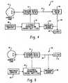
- FIG. 4 is a block diagram of a control system using one solenoid operated valve to control pressure to a clutch control valve and employing one pressure sensor to illustrate general principles of the present invention, whereas the control system of present invention as defined in the claims uses a plurality of clutches, control valves and sensors;
- FIG. 5 is a block flow diagram of another embodiment of a control system according to the principles of the present invention, shown using only one solenoid operated valve and one pressure sensor contrary to the control system of present invention as defined in the claims;
- FIG. 6 is a block diagram of the present invention employing a plurality of solenoid valves and pressure switches in a transmission having a multiplicity of shift control clutches;
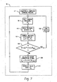
- FIG. 7 is a block flow diagram of controller operation of the system of the present invention.
- a first embodiment of a control system is indicated generally at 10 as including only one hydraulically actuated clutch for the sake of convenience to illustrate the general principles of the present invention. It is to be noted that the present invention as claimed is applied to a plurality of clutches.
- the control system of FIG. 4 is shown with a solenoid operated pressure bleed valve 12 supplied with pressurized hydraulic fluid from pump 14 which may be driven by the transmission input shaft.
- Valve 12 supplies pressurized fluid along conduit 16 to a hydraulic control valve 18, the output of which is applied through conduit 20 to a hydraulically actuated clutch 22, as for example, a band type clutch, for controlling torque transmission upon a speed (gear) change.
- the pressure supplied to the clutch along conduit 20 is sensed by a sensor 24 which provides an electrical indication of the sensed pressure, as shown by dashed line in FIG. 4 , to an electronic transmission control unit (TCU) denoted by reference numeral 26 which also receives an input in the form of a command pressure signal P c from a powertrain computer 28 which is programmed to provide the desired shift characteristics for the particular vehicle and engine-transmission combination.
- TCU transmission control unit
- FIG. 5 another embodiment of a control system according to the general principle of the present invention but reduced to only one clutch for the sake of simplicity is indicated generally at 30 wherein a pump 32 provides pressurized fluid to a pressure bleed solenoid valve 34 which is operated by an electronic transmission control unit (TCU) 36 which receives an electrical signal from pressure sensor 38 and a pressure command signal from the powertrain computer 40; and, TCU 36 is operative to provide an energization current to the valve 34.
- TCU electronic transmission control unit
- the pressurized fluid at the outlet of valve 34 is supplied along conduit 42 to an hydraulically operated shift clutch 44; and, pressure sensor 38 senses the fluid pressure in conduit 42 supplying the clutch 44 and provides an electrical indication of the sensed pressure to TCU 36 as shown in dashed outline in FIG. 5 .
- FIG. 6 another embodiment of the invention is indicated generally at 50.
- the system 50 of FIG. 6 employs a plurality of clutches such as band clutches, each of which includes an hydraulic actuator and which are denoted respectively 52 through 58 in FIG. 6 .
- Each of the clutch actuators 52 through 58 is supplied with hydraulic fluid pressure by a control valve denoted respectively 60 through 66, with each of the control valves receiving pressurized fluid from a solenoid operated valve denoted respectively 68 through 74.
- the clutch actuators 52 through 58 are each supplied pressurized fluid from the respective valves 60 through 66 by conduits denoted respectively 76 through 82; and, each of the conduits is tapped to provide a pressure signal to a pressure sensor denoted respectively 84 through 90.
- Each of the pressure sensors 84 through 90 provides an electrical input, indicated in dashed outline in FIG. 6 , to the electronic transmission control unit (TCU) denoted by reference numeral 92 which also receives a command pressure signal (P c ) from a powertrain computer 94 which contains the program and shift control algorithms for providing the desired operational drivability of the vehicle with a particular engine and transmission confirmation.
- TCU electronic transmission control unit
- P c command pressure signal
- the solenoid valves 68 through 74 each receive hydraulic fluid under pressure through conduit 95 from a hydraulic pump 96 which is commonly driven by the transmission input shaft.
- the program for the software loaded into the TCU 26, 36, 92 is shown as a flow diagram wherein the pressure command signal P c is received from one of the powertrain computers 28, 40, 94 at step 97 and the system proceeds to get or store the command pressure signal P c at step 98.
- the system then proceeds to read the sensors 24, 38, 84 through 90 at step 100 as the sensed pressure P s .
- step 104 If the determination at step 104 is affirmative, the pressure in the clutch actuators is deemed to be a match with the command pressure P c , or in other words, the differential ⁇ P is sufficiently negligible as to require no further change in pressure to the clutch actuator; and, the system returns through a time delay 106 to step 98.
- a time delay of about 10 milliseconds has been found to be satisfactory; however, other values of the time delay may be used depending upon the response capability of the transmission shift mechanism. In the present practice it has been found satisfactory to set the time delay greater than the response time of the shift mechanism to avoid "hunting".
- step 104 determines whether the determination in step 104 is negative and the value of ⁇ P exceeds the value ⁇ P MAX deemed to be negligible then the system proceeds to step 108 and calculates the error I E from predetermined known relationships between ⁇ P and the percent of maximum current for energization of the valves I MAX .
- ⁇ P MAX it has been found satisfactory to set ⁇ P MAX at about plus or minus 1 psi (6.9 kPa).
- step 110 proceeds to step 110 to energize the respective valve with the computed current I e and returns to step 98.
- the present invention thus provides a unique and simplified yet low cost technique for providing closed loop control of the shift clutch actuators in automatic speed change power transmission utilizing the sensed pressure at each clutch actuator as an analog of the torque transmitted by the clutch to provide a feedback signal to an electronic controller controlling the solenoid valves providing the pressurized hydraulic fluid to each clutch actuator.
- the present invention thus provides a simplified clutch torque feedback signal to the electronic controller eliminating the need for individual speed sensors on each of the power transmission speed change members.
Landscapes
- Engineering & Computer Science (AREA)
- General Engineering & Computer Science (AREA)
- Mechanical Engineering (AREA)
- Transportation (AREA)
- Physics & Mathematics (AREA)
- Automation & Control Theory (AREA)
- Mathematical Physics (AREA)
- Chemical & Material Sciences (AREA)
- Combustion & Propulsion (AREA)
- Control Of Transmission Device (AREA)
- Hydraulic Clutches, Magnetic Clutches, Fluid Clutches, And Fluid Joints (AREA)
- Gear-Shifting Mechanisms (AREA)
Abstract
Description
- The present invention relates to automatic shifting speed change transmissions employed in motor vehicles where electrically operated solenoid valves are controlled by an electronic computer for controlling the flow of pressurized fluid to transmission shift actuators such as band clutch actuators employed in the transmission shifting operation. The electronically controlled solenoid operated valves provide improved shifting capabilities for the transmission as compared to hydro-mechanical shift controls; and, in particular, permits staged or progressive release and application of the band clutches for effecting smoother speed changes in the transmission.
- Such valve assemblies are, in current production transmissions, mounted internally on the transmission valve body and supplied with pressurized fluid from a pump disposed in the transmission.
- Heretofore, in controlling the shifting of an automatic speed change power transmission it has been known to use a pilot operated valve to control flow to a large flow control valve for clutch actuation such as shown in
FIG. 1 .
FIG. 2 uses a VFS without need of flow control valve. - It is also known to use solenoid valves controlled by an electronic controller and to sense line pressure in order that the controller can regulate line pressure to a desired valve. An example of this latter type control is that shown and described in
U.S. Patent 4,781,080 which teaches a pressure sensor for providing a control signal to an electronic controller for operating a solenoid valve to regulate the supply pressure from the pump to a primary regulator valve. - Heretofore, in automatic shifting speed power transmissions for motor vehicles, with the advent of electronic control it has been desired to provide some power transmission during speed changes. Thus, the rate of engagement and disengagement of the individual clutch bands was controlled to permit speed changes prior to complete deactuation of the driving clutch. However, this required a very high degree of calibration of the solenoid operated valve controlling the pressure to the clutch actuator and has proven to be difficult to achieve reliably.
- The primary technique employed in these prior art systems for shift control has been the use of an algorithm in the electronic controller utilizing a known calibration curve for the solenoid valves to yield the desired pressure output based upon the current input to the valve from the controller. However, it has been found in service that the ability to calibrate and maintain the calibration of the solenoid valves to provide sufficiently accurate control of the output pressure to the shift actuators has been limited. The pressure output of the valves has shifted with temperature variations and exposure to the transmission fluid contamination and viscosity changes.
-
EP 1 150 031 A1 -
U.S. Patent 5,853,076 discloses a power shift transmission having a plurality of fluid clutches, each having a fill time extending from a first time at which the clutch is empty to a second time in which the clutch is filled with fluid from a fluid supply, valves fluidly coupled to the clutches to control the flow of fluid to each clutch, a conduit in fluid communication between each valve and the fluid supply and a pressure transducer in fluid communication with said conduit to sense the pressure at the inlet of each valve. A controller calibrates the clutch fill delay time during each transmission shift based on changes in fluid pressure sensed by the pressure transducer as clutches are engaged and disengaged. -
U.S. Patent 4,956,776 describes a device for managing an electrohydraulic pressure control of a motor vehicle automatic transmission using a modified proportional plus integral plus derivative control logic. - Thus, it has long been desired to provide a way or means of providing closed loop control of solenoid operated valves for shift clutch actuator control in an automatic speed change transmission which would obviate the need for accurate flow calibration of the solenoid valves. Furthermore, it has been desired to provide such a way or means of closed loop shift control which is low in cost and easy to manufacture for a high volume motor vehicle transmission such as employed in passenger cars and light trucks.
- Referring to
FIG. 3 , the aforesaid prior art system is shown in diagrammatic form wherein a pressure signal is provided to the transmission control unit (TCU) which controls the solenoid valve providing pump output to a line pressure regulator. - In the prior art, it is known, as for example in
U.S. Patent 4,776,233 , to detect the torque transmitted by the clutch by disposing a pair of speed sensors on the input and output members of each speed change gear set where the speed difference between the input and output member was used as an analog of torque transmitted to provide a feedback signal to the controller for the solenoid operated valve. However, as the speed sensors must be mounted on each gear set, this has been costly and difficult particularly where planetary gear sets are employed. Thus, it has been desired to provide a simple way or means of providing closed loop control with a feedback signal indicative of the torque transmitted by a particular shifting clutch band. - To meet the above desire the present invention provides a system and a method for controlling shifting in an automatic shifting gear change power transmission as claimed in
claim 1 and 6, respectively. Preferred embodiments of the present invention are subject-matter of dependent claims. - The present invention provides closed loop pressure control of hydraulically operated shift clutch actuators in an automatic speed change power transmission where the shift clutch actuators receive pressure from the outlet of an electronically controlled solenoid operated valve. The present invention is particularly applicable to automatic speed change transmissions having hydraulic actuators for operating band clutches for effecting the speed changes.
- A pressure sensor detects the pressure supplied to each of the hydraulic clutch actuators such as hydraulic piston actuators for band clutches and the sensed pressure is supplied to a transmission electronic controller (TCU) which compares the pressure with a command pressure signal sent to the transmission from the vehicle powertrain electronic controller. The current to each solenoid valve may then be varied until the difference between the command pressure signal and the sensed pressure from the hydraulic clutch actuator is sufficiently near zero as to be considered negligible and indicating a match between the command signal and the actual clutch pressure. The present invention thus provides rapidly responsive shift control inasmuch as a pressure sensor may be employed with each band clutch hydraulic actuator and the full range of speed changes for the transmission may be programmed electronically to vary the speed of the clutch engagement or disengagement as desired utilizing the clutch band actuator pressure as an analog of the torque transmitted by the clutch. The present invention provides more accurate control of the engagement and disengagement of each shift clutch and this improves the ability to change speed smoothly and to maintain power transmission during speed changes.
-
FIG. 1 is a block diagram of a prior art transmission control system; -
FIG. 2 is another block diagram of a prior art transmission shift control system; -
FIG. 3 is a block diagram of another prior art shift control system utilizing a pressure sensor signal to the electronic controller; -
FIG. 4 is a block diagram of a control system using one solenoid operated valve to control pressure to a clutch control valve and employing one pressure sensor to illustrate general principles of the present invention, whereas the control system of present invention as defined in the claims uses a plurality of clutches, control valves and sensors; -
FIG. 5 is a block flow diagram of another embodiment of a control system according to the principles of the present invention, shown using only one solenoid operated valve and one pressure sensor contrary to the control system of present invention as defined in the claims; -
FIG. 6 is a block diagram of the present invention employing a plurality of solenoid valves and pressure switches in a transmission having a multiplicity of shift control clutches; and, -
FIG. 7 is a block flow diagram of controller operation of the system of the present invention. - Referring to
FIG. 4 , a first embodiment of a control system is indicated generally at 10 as including only one hydraulically actuated clutch for the sake of convenience to illustrate the general principles of the present invention. It is to be noted that the present invention as claimed is applied to a plurality of clutches.
The control system ofFIG. 4 is shown with a solenoid operated pressure bleedvalve 12 supplied with pressurized hydraulic fluid frompump 14 which may be driven by the transmission input shaft. Valve 12 supplies pressurized fluid along conduit 16 to ahydraulic control valve 18, the output of which is applied throughconduit 20 to a hydraulically actuatedclutch 22, as for example, a band type clutch, for controlling torque transmission upon a speed (gear) change. The pressure supplied to the clutch alongconduit 20 is sensed by asensor 24 which provides an electrical indication of the sensed pressure, as shown by dashed line inFIG. 4 , to an electronic transmission control unit (TCU) denoted byreference numeral 26 which also receives an input in the form of a command pressure signal Pc from apowertrain computer 28 which is programmed to provide the desired shift characteristics for the particular vehicle and engine-transmission combination. - Referring to
FIG. 5 , another embodiment of a control system according to the general principle of the present invention but reduced to only one clutch for the sake of simplicity is indicated generally at 30 wherein apump 32 provides pressurized fluid to a pressure bleedsolenoid valve 34 which is operated by an electronic transmission control unit (TCU) 36 which receives an electrical signal frompressure sensor 38 and a pressure command signal from thepowertrain computer 40; and, TCU 36 is operative to provide an energization current to thevalve 34. The pressurized fluid at the outlet ofvalve 34 is supplied alongconduit 42 to an hydraulically operated shift clutch 44; and,pressure sensor 38 senses the fluid pressure inconduit 42 supplying the clutch 44 and provides an electrical indication of the sensed pressure toTCU 36 as shown in dashed outline inFIG. 5 . - Referring to
FIG. 6 , another embodiment of the invention is indicated generally at 50. Thesystem 50 ofFIG. 6 employs a plurality of clutches such as band clutches, each of which includes an hydraulic actuator and which are denoted respectively 52 through 58 inFIG. 6 . Each of theclutch actuators 52 through 58 is supplied with hydraulic fluid pressure by a control valve denoted respectively 60 through 66, with each of the control valves receiving pressurized fluid from a solenoid operated valve denoted respectively 68 through 74. Theclutch actuators 52 through 58 are each supplied pressurized fluid from therespective valves 60 through 66 by conduits denoted respectively 76 through 82; and, each of the conduits is tapped to provide a pressure signal to a pressure sensor denoted respectively 84 through 90. - Each of the
pressure sensors 84 through 90 provides an electrical input, indicated in dashed outline inFIG. 6 , to the electronic transmission control unit (TCU) denoted byreference numeral 92 which also receives a command pressure signal (Pc) from apowertrain computer 94 which contains the program and shift control algorithms for providing the desired operational drivability of the vehicle with a particular engine and transmission confirmation. Thesolenoid valves 68 through 74 each receive hydraulic fluid under pressure throughconduit 95 from ahydraulic pump 96 which is commonly driven by the transmission input shaft. - Referring to
FIG. 7 , the program for the software loaded into theTCU powertrain computers step 97 and the system proceeds to get or store the command pressure signal Pc atstep 98. - The system then proceeds to read the
sensors step 100 as the sensed pressure Ps. The system then proceeds to compute the pressure differential ΔP = Pc - Ps atstep 102 and proceeds to ask the question atstep 104 whether ΔP is less than a predetermined differential ΔPMAX - If the determination at
step 104 is affirmative, the pressure in the clutch actuators is deemed to be a match with the command pressure Pc, or in other words, the differential ΔP is sufficiently negligible as to require no further change in pressure to the clutch actuator; and, the system returns through atime delay 106 tostep 98. In the present practice of the invention a time delay of about 10 milliseconds has been found to be satisfactory; however, other values of the time delay may be used depending upon the response capability of the transmission shift mechanism. In the present practice it has been found satisfactory to set the time delay greater than the response time of the shift mechanism to avoid "hunting". - If the determination in
step 104 is negative and the value of ΔP exceeds the value ΔPMAX deemed to be negligible then the system proceeds tostep 108 and calculates the error IE from predetermined known relationships between ΔP and the percent of maximum current for energization of the valves IMAX. In the present practice of the invention, it has been found satisfactory to set ΔPMAX at about plus or minus 1 psi (6.9 kPa). The system them proceeds tostep 110 to energize the respective valve with the computed current Ie and returns tostep 98. - The present invention thus provides a unique and simplified yet low cost technique for providing closed loop control of the shift clutch actuators in automatic speed change power transmission utilizing the sensed pressure at each clutch actuator as an analog of the torque transmitted by the clutch to provide a feedback signal to an electronic controller controlling the solenoid valves providing the pressurized hydraulic fluid to each clutch actuator. The present invention thus provides a simplified clutch torque feedback signal to the electronic controller eliminating the need for individual speed sensors on each of the power transmission speed change members.
- Although the invention has hereinabove been described with respect to the illustrated embodiments, it will be understood that the invention is capable of modification and variation and is limited only by the following claims.
Claims (11)
- A system for controlling shifting in an automatic shifting gear change power transmission comprising:a) a plurality of clutches (52-58), each operable upon actuation to effect torque transmission between a first and a second rotatable member in said automatic transmission;b) a plurality of hydraulically operated actuators (52-58), each operatively connected for effecting actuation and deactuation of one of said clutches;c) a pump (96) providing a source of pressurized hydraulic fluid;d) a plurality of electrically operated pressure bleed valves (68-74), each receiving at its inlet said pressurized fluid from said pump, with each of said valves connected to control hydraulic pressure to one of said actuators;e) an electronic controller (92) operatively connected to provide electrical energization of each of said valves; and,f) a plurality of pressure sensors (84-90), each disposed to sense the pressure supplied to one of said actuators by the corresponding valve and operable to provide electrical signals indicative of said actual sensed pressure readings to the controller, wherein actuation of each of said actuators effects a gear change in the transmission.
- The system defined in claim 1, wherein said electrically operated pressure bleed valves include solenoid operators
- The system defined in claim 1, wherein said controller employs a proportional integral derivation (PID) algorithm of said sensor signal in energizing said valve.
- The system defined in claim 1, wherein said controller, employs a proportional integral (PI) algorithm of said sensor signal in energizing said valve
- The system defined in claim 1, wherein said pressure sensor comprises a piezoelectric sensor.
- A method of controlling shifting of an automatic multiple gear change transmission comprising:a) providing a power input and power output member in said transmission for each gear change in the transmission and disposing a clutch (52-58) for transmitting torque between the input and output member;b) disposing an hydraulically operated actuator for individually activating and deactivating each clutch;c) disposing a pump (96) in said transmission and connecting the outlet of the pump to the inlet of a plurality of electrically operated pressure bleed valves (68-74);d) connecting one of said valves to each of said actuators and controlling pressure thereto for effecting a gear change;e) disposing a plurality of pressure sensors (84-90) with one of said sensors sensing the pressure supplied to each of said actuators and generating electrical signals indicative of the actual sensed pressure readings;f) providing an electronic controller (92) for said valves and connecting each of said pressure sensors thereto and providing said electrical pressure signal to said controller for each valve; and,g) generating a control signal to each of said valves based on one of said electrical pressure signals.
- The method defined in claim 6, wherein said step of disposing an hydraulically operated actuator includes disposing a piston actuator.
- The method defined in claim 6, wherein said steps f) and g) comprise:i) providing a shift program and generating an electrical shift pressure command signal for each gear change;j) comparing said clutch pressure signal (PS) with said shift pressure command signal (PC) and calculating the error (ΔP) for each command signal;k) assigning an initial value of valve energization (IE) from a known relationship of valve energization with actuator pressure and known maximum valve energization; and,l) repeating steps i) through k) until the computed error is within a predetermined deviation from zero (Δ P
MAX ) for each command signal. - The method defined in claim 8, wherein said deviation is not greater than one psi (6.9 KPa).
- The method defined in claim 6, wherein said steps f) and g) comprise:i) providing a shift program and generating an electrical shift pressure command signal for each gear change;j) comparing each clutch pressure signal and respectively each corresponding shift pressure command signal and computing the difference;k) varying the energization of each respective valve until said difference is negligible.
- The method defined in claim 10, wherein said step of varying the energization of the valve includes generating a valve energization current as a known function of the percentage of the maximum valve energization current and the sensed pressure.
Applications Claiming Priority (2)
| Application Number | Priority Date | Filing Date | Title |
|---|---|---|---|
| US10/327,792 US6807472B2 (en) | 2002-12-23 | 2002-12-23 | Closed loop control of shifting clutch actuators in an automatic speed change transmission |
| US327792 | 2002-12-23 |
Publications (3)
| Publication Number | Publication Date |
|---|---|
| EP1433982A2 EP1433982A2 (en) | 2004-06-30 |
| EP1433982A3 EP1433982A3 (en) | 2007-04-11 |
| EP1433982B1 true EP1433982B1 (en) | 2009-04-15 |
Family
ID=32468997
Family Applications (1)
| Application Number | Title | Priority Date | Filing Date |
|---|---|---|---|
| EP03028192A Expired - Lifetime EP1433982B1 (en) | 2002-12-23 | 2003-12-09 | Closed loop control of shifting clutch actuators in an automatic speed change transmission |
Country Status (7)
| Country | Link |
|---|---|
| US (1) | US6807472B2 (en) |
| EP (1) | EP1433982B1 (en) |
| JP (1) | JP2004205044A (en) |
| KR (1) | KR20040056375A (en) |
| AT (1) | ATE428876T1 (en) |
| CA (1) | CA2453461C (en) |
| DE (1) | DE60327155D1 (en) |
Families Citing this family (32)
| Publication number | Priority date | Publication date | Assignee | Title |
|---|---|---|---|---|
| US7484429B2 (en) * | 2005-05-10 | 2009-02-03 | Eaton Corporation | Closed loop adaptive fluid control system and method |
| US7486996B2 (en) * | 2005-09-26 | 2009-02-03 | Eaton Corporation | Transmission control unit having pressure transducer package |
| US7383735B2 (en) * | 2005-09-26 | 2008-06-10 | Eaton Corporation | Pressure transducer package for a manifold |
| DE102005057805B4 (en) * | 2005-12-03 | 2017-05-18 | Bayerische Motoren Werke Aktiengesellschaft | Device for controlling an automatic transmission with an electronic control unit |
| US7614307B2 (en) * | 2006-06-06 | 2009-11-10 | Eaton Corporation | Manifold assembly having a centralized pressure sensing package |
| US20070288148A1 (en) * | 2006-06-08 | 2007-12-13 | Weijia Cui | Adaptive Open Loop Line Pressure Control Of Hydraulic Fluid In An Automatic Transmission |
| US20080082242A1 (en) * | 2006-10-03 | 2008-04-03 | Dell Eva Mark L | Mode selection and switching logic in a closed-loop pulse width modulation valve-based transmission control system |
| US8192318B2 (en) * | 2007-03-26 | 2012-06-05 | Delphi Technologies, Inc. | Automatic transmission with closed loop pressure electro-hydraulic control module |
| US20090032360A1 (en) * | 2007-08-02 | 2009-02-05 | Tetsushi Asano | Hydraulic Vehicle Clutch System and Method |
| US9611906B2 (en) * | 2007-08-02 | 2017-04-04 | Honda Motor Co., Ltd. | Hydraulic vehicle clutch system and method |
| US7979184B2 (en) * | 2007-09-19 | 2011-07-12 | Honda Motor Co., Ltd. | Automatic transmission solenoid control system and method |
| US20090222179A1 (en) * | 2008-03-03 | 2009-09-03 | Quan Zheng | Dynamic learning of solenoid p-i curves for closed loop pressure controls |
| US8170761B2 (en) * | 2008-03-03 | 2012-05-01 | Delphi Technologies, Inc. | Method for real-time learning of actuator transfer characteristics |
| US8172060B2 (en) * | 2008-04-02 | 2012-05-08 | Saturn Electonics & Engineering, Inc. | Dynamic pressure control system with solenoid valve command current trimming |
| US8762018B2 (en) * | 2008-05-01 | 2014-06-24 | Allison Transmission, Inc. | Method and apparatus for clutch pressure control |
| US8989971B2 (en) * | 2008-05-27 | 2015-03-24 | Eaton Corporation | Method and apparatus for detecting and compensating for pressure transducer errors |
| JP4539772B2 (en) * | 2008-10-10 | 2010-09-08 | トヨタ自動車株式会社 | Range judgment device |
| US8781697B2 (en) | 2011-08-31 | 2014-07-15 | GM Global Technology Operations LLC | Adaptive control systems and methods for transmission solenoids |
| AU2013287177B2 (en) * | 2012-06-13 | 2017-06-08 | Allison Transmission, Inc. | Method and apparatus for clutch pressure control |
| BR112015023271A2 (en) * | 2013-03-13 | 2017-07-18 | Dana Belgium Nv | A method for calibrating a wet clutch, the clutch comprising a pump for providing a housing with a hydraulic fluid, a piston movably disposed in the housing, the piston being able to move to an extended position by means of a preloaded spring and to a retracted position by applying a geared pressure to the piston by means of hydraulic fluid, wherein the retracted position torque can be transmitted by means of a clutch, a proportional valve arranged between the pump and the housing to regulate a fluid pressure. in the housing, a controller controlling the proportional valve, a pressure sensor for measuring a hydraulic fluid pressure in the housing, and apparatus for calibrating a wet clutch. |
| FR3004686B1 (en) * | 2013-04-23 | 2016-10-07 | Renault Sa | METHOD FOR CHECKING THE TORQUE SPEEDS OF AN AUTOMATIC TRANSMISSION |
| JP6293600B2 (en) | 2014-07-17 | 2018-03-14 | クノールブレムゼ商用車システムジャパン株式会社 | Clutch control method and automatic clutch control device |
| JP6075340B2 (en) | 2014-07-29 | 2017-02-08 | 株式会社デンソー | Hydraulic control device |
| JP6323271B2 (en) * | 2014-09-11 | 2018-05-16 | 株式会社デンソー | Control device for automatic transmission |
| US9671032B2 (en) * | 2014-10-22 | 2017-06-06 | Flextronics Ap, Llc | Dynamic current compensation |
| EP3252349A1 (en) | 2016-05-30 | 2017-12-06 | Dana Belgium N.V. | Method of shifting a vehicle transmission and vehicle driveline |
| EP3252336A1 (en) | 2016-05-30 | 2017-12-06 | Dana Belgium N.V. | Fill parameter learning for wet plate clutches based on an output of a torque converter |
| US20180266524A1 (en) * | 2017-03-16 | 2018-09-20 | Camilo Ernesto Guzman | guzman transmission |
| EP3717886B1 (en) | 2017-12-01 | 2026-03-25 | 3M Innovative Properties Company | Causal analytics for powertrain management |
| CN111075914B (en) * | 2020-03-09 | 2023-07-21 | 扬州维邦园林机械有限公司 | Control system and control method of continuously variable transmission |
| US11346377B2 (en) | 2020-08-24 | 2022-05-31 | Epiroc Drilling Solutions, Llc | System and method for automatic calibration of actuators |
| CN114738398B (en) * | 2022-05-10 | 2024-04-16 | 潍柴动力股份有限公司 | A hybrid vehicle clutch self-learning method, device and equipment |
Family Cites Families (12)
| Publication number | Priority date | Publication date | Assignee | Title |
|---|---|---|---|---|
| US4611285A (en) | 1984-04-05 | 1986-09-09 | Ford Motor Company | Method of controlling automatic transmission shift pressure |
| JPS6184446A (en) | 1984-09-29 | 1986-04-30 | Mitsubishi Motors Corp | Method of setting initial hydraulic pressure in vehicle automatic speed change gear unit |
| JPS62159842A (en) | 1986-01-07 | 1987-07-15 | Toyota Motor Corp | Oil pressure control device for automatic variable transmission |
| DE3667836D1 (en) | 1986-02-24 | 1990-02-01 | Shimadzu Corp | HYDROMECHANICAL TRANSMISSION. |
| FR2616931B1 (en) | 1987-06-22 | 1989-10-06 | Renault | DEVICE FOR MANAGING AN ELECTRO-HYDRAULIC PRESSURE CONTROL |
| JP2971071B2 (en) * | 1987-12-26 | 1999-11-02 | アイシン・エィ・ダブリュ株式会社 | Actuator for friction engagement device |
| US4919012A (en) * | 1989-03-01 | 1990-04-24 | Ford Motor Company | Pilot operated solenoid valve in an automatic transmission control circuit |
| US5062050A (en) | 1989-10-17 | 1991-10-29 | Borg-Warner Automotive, Inc. | Continuously variable transmission line pressure control |
| KR100500721B1 (en) | 1996-03-14 | 2005-11-25 | 루크 게트리에베시스템 게엠베하 | Vehicle and control method |
| US5853076A (en) * | 1996-06-27 | 1998-12-29 | Case Corporation | Method and apparatus for calibrating clutch fill rates |
| US6341552B1 (en) * | 2000-04-27 | 2002-01-29 | Eaton Corporation | Self-calibrating system and method for controlling a hydraulically operated device |
| US6655138B2 (en) * | 2001-05-01 | 2003-12-02 | Delphi Technologies, Inc. | System and method for actuating and controlling a transfer case |
-
2002
- 2002-12-23 US US10/327,792 patent/US6807472B2/en not_active Expired - Lifetime
-
2003
- 2003-12-09 DE DE60327155T patent/DE60327155D1/en not_active Expired - Lifetime
- 2003-12-09 AT AT03028192T patent/ATE428876T1/en not_active IP Right Cessation
- 2003-12-09 EP EP03028192A patent/EP1433982B1/en not_active Expired - Lifetime
- 2003-12-17 CA CA002453461A patent/CA2453461C/en not_active Expired - Fee Related
- 2003-12-22 KR KR1020030094505A patent/KR20040056375A/en not_active Ceased
- 2003-12-24 JP JP2003427870A patent/JP2004205044A/en active Pending
Also Published As
| Publication number | Publication date |
|---|---|
| CA2453461A1 (en) | 2004-06-23 |
| JP2004205044A (en) | 2004-07-22 |
| DE60327155D1 (en) | 2009-05-28 |
| EP1433982A2 (en) | 2004-06-30 |
| US6807472B2 (en) | 2004-10-19 |
| US20040122577A1 (en) | 2004-06-24 |
| ATE428876T1 (en) | 2009-05-15 |
| KR20040056375A (en) | 2004-06-30 |
| EP1433982A3 (en) | 2007-04-11 |
| CA2453461C (en) | 2008-07-15 |
Similar Documents
| Publication | Publication Date | Title |
|---|---|---|
| US6807472B2 (en) | Closed loop control of shifting clutch actuators in an automatic speed change transmission | |
| US4913004A (en) | Electronic powershift control system for an implement transmission | |
| US8401756B2 (en) | Method and apparatus for clutch pressure control | |
| EP0516309B1 (en) | Clutches | |
| US8989971B2 (en) | Method and apparatus for detecting and compensating for pressure transducer errors | |
| KR20010098914A (en) | A self-calibrating system and method for controlling a hydraulically operated device | |
| US9394952B2 (en) | Method and apparatus for clutch pressure control | |
| KR20150128679A (en) | System and method for feed forward control of a hydraulic control system of a transmission | |
| JPH01108451A (en) | Method of controlling transmission of automobile | |
| CN104813056B (en) | Method and apparatus for clutch pressure control | |
| US8762018B2 (en) | Method and apparatus for clutch pressure control | |
| US7484429B2 (en) | Closed loop adaptive fluid control system and method | |
| JPH0617845A (en) | Self-adjusting clutch actuator | |
| EP2065624B1 (en) | A method of driving an hydraulic actuator by means of a pressure-controlled proportioning solenoid valve | |
| JPH05196061A (en) | Actuator controller | |
| US20060219509A1 (en) | System and method for controlling engagement of a clutch |
Legal Events
| Date | Code | Title | Description |
|---|---|---|---|
| PUAI | Public reference made under article 153(3) epc to a published international application that has entered the european phase |
Free format text: ORIGINAL CODE: 0009012 |
|
| AK | Designated contracting states |
Kind code of ref document: A2 Designated state(s): AT BE BG CH CY CZ DE DK EE ES FI FR GB GR HU IE IT LI LU MC NL PT RO SE SI SK TR |
|
| AX | Request for extension of the european patent |
Extension state: AL LT LV MK |
|
| PUAL | Search report despatched |
Free format text: ORIGINAL CODE: 0009013 |
|
| AK | Designated contracting states |
Kind code of ref document: A3 Designated state(s): AT BE BG CH CY CZ DE DK EE ES FI FR GB GR HU IE IT LI LU MC NL PT RO SE SI SK TR |
|
| AX | Request for extension of the european patent |
Extension state: AL LT LV MK |
|
| RIC1 | Information provided on ipc code assigned before grant |
Ipc: F16H 57/04 20060101ALN20070306BHEP Ipc: F16H 61/02 20060101AFI20040329BHEP Ipc: F16H 61/00 20060101ALI20070306BHEP Ipc: F16H 61/06 20060101ALI20070306BHEP Ipc: F16H 59/68 20060101ALN20070306BHEP |
|
| 17P | Request for examination filed |
Effective date: 20071002 |
|
| 17Q | First examination report despatched |
Effective date: 20071108 |
|
| AKX | Designation fees paid |
Designated state(s): AT BE BG CH CY CZ DE DK EE ES FI FR GB GR HU IE IT LI LU MC NL PT RO SE SI SK TR |
|
| GRAP | Despatch of communication of intention to grant a patent |
Free format text: ORIGINAL CODE: EPIDOSNIGR1 |
|
| GRAS | Grant fee paid |
Free format text: ORIGINAL CODE: EPIDOSNIGR3 |
|
| GRAA | (expected) grant |
Free format text: ORIGINAL CODE: 0009210 |
|
| AK | Designated contracting states |
Kind code of ref document: B1 Designated state(s): AT BE BG CH CY CZ DE DK EE ES FI FR GB GR HU IE IT LI LU MC NL PT RO SE SI SK TR |
|
| REG | Reference to a national code |
Ref country code: GB Ref legal event code: FG4D Ref country code: CH Ref legal event code: EP |
|
| REG | Reference to a national code |
Ref country code: IE Ref legal event code: FG4D |
|
| REF | Corresponds to: |
Ref document number: 60327155 Country of ref document: DE Date of ref document: 20090528 Kind code of ref document: P |
|
| REG | Reference to a national code |
Ref country code: SE Ref legal event code: TRGR |
|
| NLV1 | Nl: lapsed or annulled due to failure to fulfill the requirements of art. 29p and 29m of the patents act | ||
| PG25 | Lapsed in a contracting state [announced via postgrant information from national office to epo] |
Ref country code: AT Free format text: LAPSE BECAUSE OF FAILURE TO SUBMIT A TRANSLATION OF THE DESCRIPTION OR TO PAY THE FEE WITHIN THE PRESCRIBED TIME-LIMIT Effective date: 20090415 Ref country code: ES Free format text: LAPSE BECAUSE OF FAILURE TO SUBMIT A TRANSLATION OF THE DESCRIPTION OR TO PAY THE FEE WITHIN THE PRESCRIBED TIME-LIMIT Effective date: 20090726 Ref country code: FI Free format text: LAPSE BECAUSE OF FAILURE TO SUBMIT A TRANSLATION OF THE DESCRIPTION OR TO PAY THE FEE WITHIN THE PRESCRIBED TIME-LIMIT Effective date: 20090415 Ref country code: PT Free format text: LAPSE BECAUSE OF FAILURE TO SUBMIT A TRANSLATION OF THE DESCRIPTION OR TO PAY THE FEE WITHIN THE PRESCRIBED TIME-LIMIT Effective date: 20090915 |
|
| PG25 | Lapsed in a contracting state [announced via postgrant information from national office to epo] |
Ref country code: NL Free format text: LAPSE BECAUSE OF FAILURE TO SUBMIT A TRANSLATION OF THE DESCRIPTION OR TO PAY THE FEE WITHIN THE PRESCRIBED TIME-LIMIT Effective date: 20090415 Ref country code: SI Free format text: LAPSE BECAUSE OF FAILURE TO SUBMIT A TRANSLATION OF THE DESCRIPTION OR TO PAY THE FEE WITHIN THE PRESCRIBED TIME-LIMIT Effective date: 20090415 |
|
| PG25 | Lapsed in a contracting state [announced via postgrant information from national office to epo] |
Ref country code: DK Free format text: LAPSE BECAUSE OF FAILURE TO SUBMIT A TRANSLATION OF THE DESCRIPTION OR TO PAY THE FEE WITHIN THE PRESCRIBED TIME-LIMIT Effective date: 20090415 Ref country code: CZ Free format text: LAPSE BECAUSE OF FAILURE TO SUBMIT A TRANSLATION OF THE DESCRIPTION OR TO PAY THE FEE WITHIN THE PRESCRIBED TIME-LIMIT Effective date: 20090415 Ref country code: EE Free format text: LAPSE BECAUSE OF FAILURE TO SUBMIT A TRANSLATION OF THE DESCRIPTION OR TO PAY THE FEE WITHIN THE PRESCRIBED TIME-LIMIT Effective date: 20090415 Ref country code: RO Free format text: LAPSE BECAUSE OF FAILURE TO SUBMIT A TRANSLATION OF THE DESCRIPTION OR TO PAY THE FEE WITHIN THE PRESCRIBED TIME-LIMIT Effective date: 20090415 |
|
| PLBE | No opposition filed within time limit |
Free format text: ORIGINAL CODE: 0009261 |
|
| STAA | Information on the status of an ep patent application or granted ep patent |
Free format text: STATUS: NO OPPOSITION FILED WITHIN TIME LIMIT |
|
| PG25 | Lapsed in a contracting state [announced via postgrant information from national office to epo] |
Ref country code: BE Free format text: LAPSE BECAUSE OF FAILURE TO SUBMIT A TRANSLATION OF THE DESCRIPTION OR TO PAY THE FEE WITHIN THE PRESCRIBED TIME-LIMIT Effective date: 20090415 Ref country code: SK Free format text: LAPSE BECAUSE OF FAILURE TO SUBMIT A TRANSLATION OF THE DESCRIPTION OR TO PAY THE FEE WITHIN THE PRESCRIBED TIME-LIMIT Effective date: 20090415 |
|
| 26N | No opposition filed |
Effective date: 20100118 |
|
| PG25 | Lapsed in a contracting state [announced via postgrant information from national office to epo] |
Ref country code: BG Free format text: LAPSE BECAUSE OF FAILURE TO SUBMIT A TRANSLATION OF THE DESCRIPTION OR TO PAY THE FEE WITHIN THE PRESCRIBED TIME-LIMIT Effective date: 20090715 |
|
| PGFP | Annual fee paid to national office [announced via postgrant information from national office to epo] |
Ref country code: DE Payment date: 20100226 Year of fee payment: 7 |
|
| PG25 | Lapsed in a contracting state [announced via postgrant information from national office to epo] |
Ref country code: MC Free format text: LAPSE BECAUSE OF NON-PAYMENT OF DUE FEES Effective date: 20100701 |
|
| REG | Reference to a national code |
Ref country code: CH Ref legal event code: PL |
|
| PG25 | Lapsed in a contracting state [announced via postgrant information from national office to epo] |
Ref country code: GR Free format text: LAPSE BECAUSE OF FAILURE TO SUBMIT A TRANSLATION OF THE DESCRIPTION OR TO PAY THE FEE WITHIN THE PRESCRIBED TIME-LIMIT Effective date: 20090716 Ref country code: IE Free format text: LAPSE BECAUSE OF NON-PAYMENT OF DUE FEES Effective date: 20091209 Ref country code: LI Free format text: LAPSE BECAUSE OF NON-PAYMENT OF DUE FEES Effective date: 20091231 Ref country code: CH Free format text: LAPSE BECAUSE OF NON-PAYMENT OF DUE FEES Effective date: 20091231 |
|
| PG25 | Lapsed in a contracting state [announced via postgrant information from national office to epo] |
Ref country code: LU Free format text: LAPSE BECAUSE OF NON-PAYMENT OF DUE FEES Effective date: 20091209 |
|
| PG25 | Lapsed in a contracting state [announced via postgrant information from national office to epo] |
Ref country code: HU Free format text: LAPSE BECAUSE OF FAILURE TO SUBMIT A TRANSLATION OF THE DESCRIPTION OR TO PAY THE FEE WITHIN THE PRESCRIBED TIME-LIMIT Effective date: 20091016 |
|
| PG25 | Lapsed in a contracting state [announced via postgrant information from national office to epo] |
Ref country code: TR Free format text: LAPSE BECAUSE OF FAILURE TO SUBMIT A TRANSLATION OF THE DESCRIPTION OR TO PAY THE FEE WITHIN THE PRESCRIBED TIME-LIMIT Effective date: 20090415 |
|
| PG25 | Lapsed in a contracting state [announced via postgrant information from national office to epo] |
Ref country code: CY Free format text: LAPSE BECAUSE OF FAILURE TO SUBMIT A TRANSLATION OF THE DESCRIPTION OR TO PAY THE FEE WITHIN THE PRESCRIBED TIME-LIMIT Effective date: 20090415 |
|
| REG | Reference to a national code |
Ref country code: DE Ref legal event code: R119 Ref document number: 60327155 Country of ref document: DE Effective date: 20110701 |
|
| PG25 | Lapsed in a contracting state [announced via postgrant information from national office to epo] |
Ref country code: DE Free format text: LAPSE BECAUSE OF NON-PAYMENT OF DUE FEES Effective date: 20110701 |
|
| REG | Reference to a national code |
Ref country code: FR Ref legal event code: PLFP Year of fee payment: 13 |
|
| PGFP | Annual fee paid to national office [announced via postgrant information from national office to epo] |
Ref country code: SE Payment date: 20151207 Year of fee payment: 13 |
|
| PGFP | Annual fee paid to national office [announced via postgrant information from national office to epo] |
Ref country code: IT Payment date: 20151210 Year of fee payment: 13 |
|
| REG | Reference to a national code |
Ref country code: FR Ref legal event code: PLFP Year of fee payment: 14 |
|
| REG | Reference to a national code |
Ref country code: SE Ref legal event code: EUG |
|
| PG25 | Lapsed in a contracting state [announced via postgrant information from national office to epo] |
Ref country code: SE Free format text: LAPSE BECAUSE OF NON-PAYMENT OF DUE FEES Effective date: 20161210 |
|
| PG25 | Lapsed in a contracting state [announced via postgrant information from national office to epo] |
Ref country code: IT Free format text: LAPSE BECAUSE OF NON-PAYMENT OF DUE FEES Effective date: 20161209 |
|
| REG | Reference to a national code |
Ref country code: FR Ref legal event code: PLFP Year of fee payment: 15 |
|
| REG | Reference to a national code |
Ref country code: GB Ref legal event code: 732E Free format text: REGISTERED BETWEEN 20181115 AND 20181130 |
|
| PGFP | Annual fee paid to national office [announced via postgrant information from national office to epo] |
Ref country code: FR Payment date: 20181127 Year of fee payment: 16 Ref country code: GB Payment date: 20181127 Year of fee payment: 16 |
|
| GBPC | Gb: european patent ceased through non-payment of renewal fee |
Effective date: 20191209 |
|
| PG25 | Lapsed in a contracting state [announced via postgrant information from national office to epo] |
Ref country code: GB Free format text: LAPSE BECAUSE OF NON-PAYMENT OF DUE FEES Effective date: 20191209 Ref country code: FR Free format text: LAPSE BECAUSE OF NON-PAYMENT OF DUE FEES Effective date: 20191231 |