EP1433702A1 - Overboard venting inflation system and control valve therefor - Google Patents
Overboard venting inflation system and control valve therefor Download PDFInfo
- Publication number
- EP1433702A1 EP1433702A1 EP20030024568 EP03024568A EP1433702A1 EP 1433702 A1 EP1433702 A1 EP 1433702A1 EP 20030024568 EP20030024568 EP 20030024568 EP 03024568 A EP03024568 A EP 03024568A EP 1433702 A1 EP1433702 A1 EP 1433702A1
- Authority
- EP
- European Patent Office
- Prior art keywords
- outlet port
- chamber
- inflation system
- enclosure
- fluid
- Prior art date
- Legal status (The legal status is an assumption and is not a legal conclusion. Google has not performed a legal analysis and makes no representation as to the accuracy of the status listed.)
- Granted
Links
- 238000013022 venting Methods 0.000 title claims description 11
- 239000012530 fluid Substances 0.000 claims description 33
- 238000004891 communication Methods 0.000 claims description 11
- 230000000717 retained effect Effects 0.000 claims description 4
- 230000000903 blocking effect Effects 0.000 claims description 3
- 239000007787 solid Substances 0.000 claims 3
- 230000001105 regulatory effect Effects 0.000 description 6
- 239000000428 dust Substances 0.000 description 2
- 239000002360 explosive Substances 0.000 description 2
- 238000000034 method Methods 0.000 description 2
- 238000012354 overpressurization Methods 0.000 description 2
- 230000003190 augmentative effect Effects 0.000 description 1
- 238000010276 construction Methods 0.000 description 1
- 238000007599 discharging Methods 0.000 description 1
- 238000007689 inspection Methods 0.000 description 1
- 230000007246 mechanism Effects 0.000 description 1
- 238000012986 modification Methods 0.000 description 1
- 230000004048 modification Effects 0.000 description 1
- 230000007935 neutral effect Effects 0.000 description 1
- 238000000926 separation method Methods 0.000 description 1
- XLYOFNOQVPJJNP-UHFFFAOYSA-N water Substances O XLYOFNOQVPJJNP-UHFFFAOYSA-N 0.000 description 1
Images

Classifications
-
- B—PERFORMING OPERATIONS; TRANSPORTING
- B64—AIRCRAFT; AVIATION; COSMONAUTICS
- B64D—EQUIPMENT FOR FITTING IN OR TO AIRCRAFT; FLIGHT SUITS; PARACHUTES; ARRANGEMENT OR MOUNTING OF POWER PLANTS OR PROPULSION TRANSMISSIONS IN AIRCRAFT
- B64D25/00—Emergency apparatus or devices, not otherwise provided for
- B64D25/08—Ejecting or escaping means
- B64D25/14—Inflatable escape chutes
-
- F—MECHANICAL ENGINEERING; LIGHTING; HEATING; WEAPONS; BLASTING
- F16—ENGINEERING ELEMENTS AND UNITS; GENERAL MEASURES FOR PRODUCING AND MAINTAINING EFFECTIVE FUNCTIONING OF MACHINES OR INSTALLATIONS; THERMAL INSULATION IN GENERAL
- F16K—VALVES; TAPS; COCKS; ACTUATING-FLOATS; DEVICES FOR VENTING OR AERATING
- F16K17/00—Safety valves; Equalising valves, e.g. pressure relief valves
- F16K17/02—Safety valves; Equalising valves, e.g. pressure relief valves opening on surplus pressure on one side; closing on insufficient pressure on one side
- F16K17/04—Safety valves; Equalising valves, e.g. pressure relief valves opening on surplus pressure on one side; closing on insufficient pressure on one side spring-loaded
- F16K17/048—Safety valves; Equalising valves, e.g. pressure relief valves opening on surplus pressure on one side; closing on insufficient pressure on one side spring-loaded combined with other safety valves, or with pressure control devices
-
- F—MECHANICAL ENGINEERING; LIGHTING; HEATING; WEAPONS; BLASTING
- F16—ENGINEERING ELEMENTS AND UNITS; GENERAL MEASURES FOR PRODUCING AND MAINTAINING EFFECTIVE FUNCTIONING OF MACHINES OR INSTALLATIONS; THERMAL INSULATION IN GENERAL
- F16K—VALVES; TAPS; COCKS; ACTUATING-FLOATS; DEVICES FOR VENTING OR AERATING
- F16K17/00—Safety valves; Equalising valves, e.g. pressure relief valves
- F16K17/02—Safety valves; Equalising valves, e.g. pressure relief valves opening on surplus pressure on one side; closing on insufficient pressure on one side
- F16K17/14—Safety valves; Equalising valves, e.g. pressure relief valves opening on surplus pressure on one side; closing on insufficient pressure on one side with fracturing member
-
- Y—GENERAL TAGGING OF NEW TECHNOLOGICAL DEVELOPMENTS; GENERAL TAGGING OF CROSS-SECTIONAL TECHNOLOGIES SPANNING OVER SEVERAL SECTIONS OF THE IPC; TECHNICAL SUBJECTS COVERED BY FORMER USPC CROSS-REFERENCE ART COLLECTIONS [XRACs] AND DIGESTS
- Y10—TECHNICAL SUBJECTS COVERED BY FORMER USPC
- Y10T—TECHNICAL SUBJECTS COVERED BY FORMER US CLASSIFICATION
- Y10T137/00—Fluid handling
- Y10T137/3584—Inflatable article [e.g., tire filling chuck and/or stem]
- Y10T137/36—With pressure-responsive pressure-control means
Definitions
- the present invention is directed toward inflation systems, in particular toward inflation systems used for inflating an inflatable member such as an emergency evacuation slide used on a commercial aircraft.
- Inflatable evacuation slides are normally stored folded in an uninflated condition in a pack requiring a minimum amount of space.
- the pack is stored in a compartment attached to or immediately adjacent the aircraft exit door.
- the slide is typically attached to the airframe such that if the aircraft exit door is opened in the "armed" condition, the evacuation slide will be automatically ejected and inflated.
- the evacuation slide is most commonly stored outside the aircraft pressure hull in an enclosure within the contour of the aircraft skin on the fuselage, wing or fairing.
- the enclosure has a door that fits flush with the external skin of the aircraft.
- the door is remotely actuated to fall away as the evacuation slide is inflated.
- a seal be maintained between the door and the evacuation slide enclosure.
- Modem evacuation slide inflation systems typically comprise a pressure vessel containing a stored pressurized gas, either alone or in combination with a pyrotechnic gas generator, used to supply the source gas for inflation of the emergency evacuation slide.
- Regulations require inflation systems that use stored gas to have an overpressure relief valve to release gas in the event of overpressurization of the inflation system pressure vessel.
- overpressure relief valves vent excess gas through a diffuser that vents the excess gas to the atmosphere. Because of the relatively large volume inside an aircraft cabin, for cabin-mounted inflation systems, venting of an overpressure relief valve to the atmosphere does not pose any serious safety concerns.
- the present invention solves the foregoing need by providing an inflation system for inflating an inflatable evacuation slide that includes an overboard venting means for safely venting gas from an overpressure relief valve or other safety device without overpressurizing the enclosure or its surroundings.
- the inflation system comprises an enclosure containing an uninflated evacuation slide. The enclosure is sealed by means of a tightly fitting enclosure door that optionally includes a seal for excluding dirt and moisture.
- the system also includes a source of pressurized gas comprising a conventional pyrotechnic gas generator, stored pressurized gas, or hybrid inflator consisting of at least of at least one stored inflation gas augmented by a pyrotechnic gas generator.
- the inflation system includes a control valve that, in response to a trigger such as from opening an emergency evacuation door in the "armed" condition, opens to begin a flow of inflation gas from the pressure vessel to the emergency evacuation slide.
- the control valve may optionally include a regulator that regulates the relatively high pressure in the storage vessel down to a lower pressure for safe inflation of the emergency evacuation slide or, if aspirators are used, down to the optimum pressure for operation of the aspirators.
- the control valve includes an overpressure relief vent, which vents inflation gas outside of the inflatable member.
- the overpressure relief vent of the present invention comprises a directional vent connected to a conduit. The conduit passes from the control valve to an opening in the aircraft fuselage, which allows any vented gas to be safely directed away from the inflation system enclosure.
- Evacuation system 100 comprises a folded uninflated evacuation slide 106 stored within an enclosure 108 that is suitably mounted to aircraft fuselage 104 for example by screws, rivets or the like.
- An inflation source 110 is attached to the rear of enclosure 108.
- Inflation source 110 may comprise a gas generator, stored compressed gas, or a combination thereof in which the stored compressed gas is housed within a pressure vessel 112.
- Inflation source 110 is connected via a control valve 200 to the inflation port of evacuation slide 106.
- Enclosure door 114 fits flush into the reveal 116 of enclosure 108 to form a smooth continuous part of the exterior surface of aircraft fuselage 104. A seal is maintained between door 114 and enclosure 108 to substantially exclude moisture and dust from entering enclosure 108. Door 114 is retained by a plurality of locks 118 that are pneumatically actuated by inflation source 110 to release door 114 as evacuation slide 106 inflates and distends from enclosure 108.
- control valve 200 comprises a regulator valve having a valve body 203 with an inlet port 205, a charging port 206, a first chamber 207, a second chamber 211, a regulator vent 213, an outlet port 215 and an overpressure vent 209.
- Inlet port 205 and charging port 206 are in fluid communication with first chamber 207, which has a first outlet 217 and a second outlet 219.
- First outlet 217 is blocked by a primary valve 221.
- Primary valve 221 opens in response to a signal (e.g., from the opening of an aircraft exit door in the "armed” condition) to begin the flow of inflation gas from pressure vessel 112 to second chamber 211 via first chamber 207.
- Second chamber 211 is in fluid communication with outlet port 215 and/or regulator vent 213.
- Outlet port 215, in turn, is in fluid communication with inflatable evacuation slide 106 (FIG. 1).
- Regulating piston 225 comprises a piston 224 and a regulator spring 226.
- Piston 224 moves within second chamber 211 such that the regulating piston 225 allows fluid communication between the second chamber 211 and the outlet port 215 as necessary to regulate the pressure at outlet port 215.
- Overpressure relief member 223 prevents fluid communication between the first chamber 207 and overpressure vent 209.
- Overpressure relief member 223 may be a conventional burst disk, check valve or other means to prevent fluid communication between first chamber 207 and overpressure vent 209 below a threshold pressure. If the pressure in first chamber 207 exceeds a predetermined threshold, however, overpressure relief member 223 ruptures (in the case of a burst disk) or opens (in the case of a check valve) to vent the overpressure through overpressure vent 209.
- control valve 200 includes a fill valve 233 and a fusable plug 235, which are installed in charging port 206.
- Control valve 200 may also have a second port 237 and a pressure indication device 239 installed in second port 237.
- the output pressure of the pressure regulation feature of control valve 200 of the illustrative embodiment may be adjustable by means of a threaded regulation spring adjuster 228. Use of a regulating spring adjuster 228 will compensate for tolerances in the spring rate and free height of the regulating spring 226. This is done by moving the regulating spring adjuster 228 either closer to piston 224 to further compress regulating spring 226 or further away from piston 224 to allow the regulator spring 226 to further expand.
- primary valve 221 comprises an electro-explosively operated ball valve in which an electro-explosive piston actuator (not shown) drives a gear rack.
- the rack acts on a pinion gear to rotate the ball valve member from a closed to an open position.
- An actuator such as an electro-explosive device (EED) or a spring operated knife blade could be used to rupture the burst disk in response to the external signal.
- the primary valve may be a burst disk with a very low burst pressure that is supported by a removable support. Removal of the support would cause the burst disk to rupture at a relatively low fluid pressure.
- overpressure relief member 233 will allow the overpressure to be exhausted through overpressure vent 209.
- Overpressure vent 209 is in fluid communication with conduit 310 which comprises a rigid or rigid/flexible tubular member terminating at an aperture 312 formed in reveal 116 of enclosure 108. Use of conduit 310 in combination with directional overpressure vent 209 permits the overpressure to be safely exhausted outside the enclosure 108.
- aperture 312 may be sealed by means of a plug 410 retained either by friction alone or by means of a shear pin 412.
- Plug 410 prevents moisture and dust from entering aperture 312 and conduit 310.
- plug 510 may comprise a frangible plug designed to burst at the appropriate pressure within conduit 310.
- conduit 310 is connected to a drain mast 610 attached to aircraft fuselage 104 in lieu of draining through an aperture 312 in reveal 116 of enclosure 108. Drain mast 610 may or may not include a plug to prevent entry of moisture and dirt into conduit 310.
Landscapes
- Engineering & Computer Science (AREA)
- General Engineering & Computer Science (AREA)
- Mechanical Engineering (AREA)
- Business, Economics & Management (AREA)
- Emergency Management (AREA)
- Aviation & Aerospace Engineering (AREA)
- Safety Valves (AREA)
Abstract
Description
- The present invention is directed toward inflation systems, in particular toward inflation systems used for inflating an inflatable member such as an emergency evacuation slide used on a commercial aircraft.
- Inflatable evacuation slides are normally stored folded in an uninflated condition in a pack requiring a minimum amount of space. Typically the pack is stored in a compartment attached to or immediately adjacent the aircraft exit door. The slide is typically attached to the airframe such that if the aircraft exit door is opened in the "armed" condition, the evacuation slide will be automatically ejected and inflated. For over-wing evacuation systems, the evacuation slide is most commonly stored outside the aircraft pressure hull in an enclosure within the contour of the aircraft skin on the fuselage, wing or fairing. The enclosure has a door that fits flush with the external skin of the aircraft. The door is remotely actuated to fall away as the evacuation slide is inflated. For aerodynamic reasons it is desirable that the remotely actuated door fit tight and flush against the external skin of the aircraft. Similarly, in order to prevent water, de-icing fluids or other containments from entering the evacuation slide enclosure, it is desirable that a seal be maintained between the door and the evacuation slide enclosure.
- Modem evacuation slide inflation systems typically comprise a pressure vessel containing a stored pressurized gas, either alone or in combination with a pyrotechnic gas generator, used to supply the source gas for inflation of the emergency evacuation slide. Regulations require inflation systems that use stored gas to have an overpressure relief valve to release gas in the event of overpressurization of the inflation system pressure vessel. Typically such overpressure relief valves vent excess gas through a diffuser that vents the excess gas to the atmosphere. Because of the relatively large volume inside an aircraft cabin, for cabin-mounted inflation systems, venting of an overpressure relief valve to the atmosphere does not pose any serious safety concerns. For externally mounted inflation systems, however, pressure build-up within the evacuation system enclosure resulting from the venting of an overpressure relief valve could result in a catastrophic in-flight separation of the enclosure door or enclosure itself from the aircraft. Thus, what is needed is a an inflation system having a tight, flush fitting enclosure door while at the same time having a control valve that safely vents gas from an overpressure relief valve without overpressurizing the emergency evacuation slide enclosure.
- The present invention solves the foregoing need by providing an inflation system for inflating an inflatable evacuation slide that includes an overboard venting means for safely venting gas from an overpressure relief valve or other safety device without overpressurizing the enclosure or its surroundings. According to one embodiment of the invention, the inflation system comprises an enclosure containing an uninflated evacuation slide. The enclosure is sealed by means of a tightly fitting enclosure door that optionally includes a seal for excluding dirt and moisture. The system also includes a source of pressurized gas comprising a conventional pyrotechnic gas generator, stored pressurized gas, or hybrid inflator consisting of at least of at least one stored inflation gas augmented by a pyrotechnic gas generator. The inflation system includes a control valve that, in response to a trigger such as from opening an emergency evacuation door in the "armed" condition, opens to begin a flow of inflation gas from the pressure vessel to the emergency evacuation slide. The control valve may optionally include a regulator that regulates the relatively high pressure in the storage vessel down to a lower pressure for safe inflation of the emergency evacuation slide or, if aspirators are used, down to the optimum pressure for operation of the aspirators. The control valve includes an overpressure relief vent, which vents inflation gas outside of the inflatable member. In lieu of the neutral thrust overpressure relief vents used in prior art regulator valves, however, the overpressure relief vent of the present invention comprises a directional vent connected to a conduit. The conduit passes from the control valve to an opening in the aircraft fuselage, which allows any vented gas to be safely directed away from the inflation system enclosure.
- The present invention will be better understood from a reading of the following detailed description taken in conjunction with the accompanying drawing figures in which like references designate like elements and, in which:
- FIG. 1 is an exploded perspective view showing an inflation system incorporating features of the present invention;
- FIG. 2 is a cross-sectional view of a control valve incorporating features of the present invention;
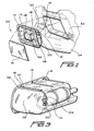
- FIG. 3 is a rear perspective view of an inflation system incorporating features of the present invention;
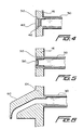
- FIG. 4 is a cross-section view of an aperture for venting inflation gas in accordance with the present invention;
- FIG. 5 is a cross-section view of an alternative aperture for venting inflation gas in accordance with the present invention; and
- FIG. 6 is a cross-section view of an alternative aperture for venting inflation gas in accordance with the present invention.
-
- The drawing figures are intended to illustrate the general manner of construction and are not necessarily to scale. In the detailed description and in the drawing figures, specific illustrative examples are shown and are herein described in detail. It should be understood, however, that the drawing figures and detailed description are not intended to limit the invention to the particular form disclosed, but are merely illustrative and intended to teach one of ordinary skill how to make and/or use the invention claimed herein and for setting forth the best mode for carrying out the invention.
- With reference to FIG. 1, for over-wing and other emergency evacuation slides that are not conveniently stored inside the pressure hull of an aircraft, it is desirable to install the
evacuation slide system 100 in a non-pressurizedcompartment 102 formed inaircraft fuselage 104 outside the pressure hull of the aircraft.Evacuation system 100 comprises a foldeduninflated evacuation slide 106 stored within anenclosure 108 that is suitably mounted toaircraft fuselage 104 for example by screws, rivets or the like. Aninflation source 110 is attached to the rear ofenclosure 108.Inflation source 110 may comprise a gas generator, stored compressed gas, or a combination thereof in which the stored compressed gas is housed within apressure vessel 112.Inflation source 110 is connected via acontrol valve 200 to the inflation port ofevacuation slide 106. -
Enclosure door 114 fits flush into thereveal 116 ofenclosure 108 to form a smooth continuous part of the exterior surface ofaircraft fuselage 104. A seal is maintained betweendoor 114 andenclosure 108 to substantially exclude moisture and dust from enteringenclosure 108.Door 114 is retained by a plurality oflocks 118 that are pneumatically actuated byinflation source 110 to releasedoor 114 asevacuation slide 106 inflates and distends fromenclosure 108. As can be seen from an inspection of FIG.1, because the clearance betweenenclosure 108 andcompartment 102 is small and becausedoor 114 fits tightly againstenclosure 108, sudden discharge of overpressure from control valve 200 (for example in the event of overcharging ofpressure vessel 112 or accidental ignition of a pyrotechnic generator discharging into pressure vessel 112) could potentially cause a build up of pressure causing eitherdoor 114 to be forced open orenclosure 108 to be ejected fromcompartment 102. - With reference to FIG. 2, although the present invention may be implemented with a control valve that does not include a pressure regulation capability, in the illustrative embodiment,
control valve 200 comprises a regulator valve having avalve body 203 with aninlet port 205, acharging port 206, afirst chamber 207, asecond chamber 211, aregulator vent 213, anoutlet port 215 and anoverpressure vent 209. -
Inlet port 205 andcharging port 206 are in fluid communication withfirst chamber 207, which has afirst outlet 217 and asecond outlet 219.First outlet 217 is blocked by aprimary valve 221.Primary valve 221 opens in response to a signal (e.g., from the opening of an aircraft exit door in the "armed" condition) to begin the flow of inflation gas frompressure vessel 112 tosecond chamber 211 viafirst chamber 207.Second chamber 211 is in fluid communication withoutlet port 215 and/orregulator vent 213.Outlet port 215, in turn, is in fluid communication with inflatable evacuation slide 106 (FIG. 1). Regulatingpiston 225 comprises apiston 224 and aregulator spring 226. Piston 224 moves withinsecond chamber 211 such that the regulatingpiston 225 allows fluid communication between thesecond chamber 211 and theoutlet port 215 as necessary to regulate the pressure atoutlet port 215.Overpressure relief member 223 prevents fluid communication between thefirst chamber 207 andoverpressure vent 209.Overpressure relief member 223 may be a conventional burst disk, check valve or other means to prevent fluid communication betweenfirst chamber 207 andoverpressure vent 209 below a threshold pressure. If the pressure infirst chamber 207 exceeds a predetermined threshold, however,overpressure relief member 223 ruptures (in the case of a burst disk) or opens (in the case of a check valve) to vent the overpressure throughoverpressure vent 209. - In the illustrative embodiment,
control valve 200 includes afill valve 233 and afusable plug 235, which are installed incharging port 206.Control valve 200 may also have asecond port 237 and apressure indication device 239 installed insecond port 237. The output pressure of the pressure regulation feature ofcontrol valve 200 of the illustrative embodiment may be adjustable by means of a threaded regulation spring adjuster 228. Use of a regulatingspring adjuster 228 will compensate for tolerances in the spring rate and free height of the regulatingspring 226. This is done by moving the regulatingspring adjuster 228 either closer topiston 224 to further compress regulatingspring 226 or further away frompiston 224 to allow theregulator spring 226 to further expand. - In a preferred embodiment,
primary valve 221 comprises an electro-explosively operated ball valve in which an electro-explosive piston actuator (not shown) drives a gear rack. The rack, in turn, acts on a pinion gear to rotate the ball valve member from a closed to an open position. There are, however, other primary valve mechanisms that would be suitable. For example, a burst disk with a high rupture pressure could be used for the blocking means. An actuator such as an electro-explosive device (EED) or a spring operated knife blade could be used to rupture the burst disk in response to the external signal. In another example, the primary valve may be a burst disk with a very low burst pressure that is supported by a removable support. Removal of the support would cause the burst disk to rupture at a relatively low fluid pressure. - With reference to FIGs. 2 and 3, in the event of an overpressurization of
first chamber 207,overpressure relief member 233 will allow the overpressure to be exhausted throughoverpressure vent 209.Overpressure vent 209 is in fluid communication withconduit 310 which comprises a rigid or rigid/flexible tubular member terminating at anaperture 312 formed inreveal 116 ofenclosure 108. Use ofconduit 310 in combination withdirectional overpressure vent 209 permits the overpressure to be safely exhausted outside theenclosure 108. - With reference to FIG. 4,
aperture 312 may be sealed by means of aplug 410 retained either by friction alone or by means of ashear pin 412.Plug 410 prevents moisture and dust from enteringaperture 312 andconduit 310. Alternatively as shown in FIG. 5plug 510 may comprise a frangible plug designed to burst at the appropriate pressure withinconduit 310. In another alternative embodiment as shown in FIG. 6,conduit 310 is connected to adrain mast 610 attached toaircraft fuselage 104 in lieu of draining through anaperture 312 inreveal 116 ofenclosure 108.Drain mast 610 may or may not include a plug to prevent entry of moisture and dirt intoconduit 310. - Although certain illustrative embodiments and methods have been disclosed herein, it will be apparent from the foregoing disclosure to those skilled in the art that variations and modifications of such embodiments and methods may be made without departing from the spirit and scope of the invention. Accordingly, it is intended that the invention shall be limited only to the extent required by the appended claims and the rules and principals of applicable law.
Claims (12)
- An inflation system for inflating an inflatable evacuation slide carried in an uninflated condition within an aircraft fuselage, wing or fairing, said inflation system comprising:a control valve, a conduit, and an overboard venting means;said control valve comprising a valve body having an inlet port, a first chamber, a primary valve, a primary outlet port, an overpressure relief member, and a secondary outlet port;said inlet port being fluidically interconnected with said first chamber and adapted to receive a flow of pressurized fluid from a pressure source and deliver said flow of pressurized fluid to said first chamber;said primary valve being disposed in a fluid path between said first chamber and said primary outlet port, said primary valve opening in responsive to an external signal to permit a flow of pressurized fluid from said first chamber to said primary outlet port;said primary outlet port being in fluid communication with said inflatable device for delivering said flow of pressurized fluid to said inflatable evacuation slide;said secondary outlet port providing a fluid path from said first chamber to said conduit;said overpressure relief member being disposed in said fluid path from said first chamber to through said secondary outlet port, said overpressure relief member blocking fluid flow from said first chamber through said secondary outlet port, said overpressure relief member being moveable in response to fluid pressure in said first chamber exceeding a predetermined threshold to permit fluid flow through said secondary outlet port;said conduit comprising a tubular member in fluid communication with said secondary outlet port for conveying a fluid flow from said secondary outlet port to said overboard venting means, andsaid overboard venting means comprising an aperture passing through said aircraft fuselage.
- The inflation system of claim 1, further comprising:a burst plug, said burst plug comprising a frangible plug disposed in said aperture passing through said aircraft fuselage.
- The inflation system of claim1, further comprising:a solid plug disposed in said aperture passing through said aircraft fuselage.
- The inflation system of claim 3, wherein:said solid plug is retained in said aperture by means of a shear pin.
- The inflation system of claim 3, wherein:said solid plug is retained in said aperture by means of a friction fit.
- The inflation system of claim 1, further comprising:a drain mast mounted to said aircraft fuselage for providing an overboard vent distal of an outer surface of said aircraft fuselage.
- The inflation system of claim 1, wherein:said overpressure relief member comprises a rupture disk.
- The inflation system of claim 1, wherein:said overpressure relief member comprises a check valve.
- The inflation system of claim 1, further comprising:a gas source, said gas source comprising a pressure vessel having a pressurized gas contained therein.
- The inflation system of claim 1, further comprising:an enclosure for containing said inflatable evacuation slide, said enclosure comprising a housing having a mounting flange and an enclosure door, wherein said aperture passing through said aircraft fuselage comprises an aperture disposed in said mounting flange.
- The inflation system of claim 1, further comprising:an enclosure for containing said inflatable evacuation slide, said enclosure comprising a housing having a mounting flange and an enclosure door, wherein said aperture passing through said aircraft fuselage comprises an aperture disposed in said enclosure door.
- An inflation system for inflating an inflatable evacuation slide carried in an uninflated condition within the contour of an aircraft skin, said inflation system comprising:an enclosure adapted to be mounted within said contour of an aircraft skin having an opening substantially flush with an exterior surface of said aircraft fuselage;an enclosure door covering said opening;a pressure vessel for storing a source of pressurized gasa control valve; anda conduit;said control valve comprising a valve body having an inlet port, a first chamber, a primary valve, a primary outlet port, and a secondary outlet port;said inlet port being fluidically interconnected with said first chamber and adapted to receive a flow of pressurized fluid from said pressure vessel and to deliver said flow of pressurized fluid to said first chamber;said primary valve being disposed in a fluid path between said first chamber and said primary outlet port, said primary valve being responsive to a trigger for providing a flow of pressurized fluid from said first chamber to said primary outlet port, said primary outlet port being in fluid communication with said inflatable evacuation slide for delivering said flow of pressurized fluid to said inflatable evacuation slide;said secondary outlet port being fluidically interconnected with said first chamber and having an overpressure relief member blocking a fluid flow from said first chamber through said secondary outlet port, said overpressure relief member being moveable in response to fluid pressure within said first chamber exceeding a predetermined threshold to permit fluid flow through said secondary outlet port;said conduit comprising a tubular member in fluid communication with said secondary outlet port for conveying a fluid flow from said secondary outlet port to an aperture in said aircraft skin.
Applications Claiming Priority (2)
| Application Number | Priority Date | Filing Date | Title |
|---|---|---|---|
| US10/328,557 US6659404B1 (en) | 2002-12-23 | 2002-12-23 | Overboard venting inflation system and control valve therefor |
| US328557 | 2002-12-23 |
Publications (2)
| Publication Number | Publication Date |
|---|---|
| EP1433702A1 true EP1433702A1 (en) | 2004-06-30 |
| EP1433702B1 EP1433702B1 (en) | 2006-10-18 |
Family
ID=29711843
Family Applications (1)
| Application Number | Title | Priority Date | Filing Date |
|---|---|---|---|
| EP20030024568 Expired - Lifetime EP1433702B1 (en) | 2002-12-23 | 2003-10-28 | Overboard venting inflation system and control valve therefor |
Country Status (3)
| Country | Link |
|---|---|
| US (1) | US6659404B1 (en) |
| EP (1) | EP1433702B1 (en) |
| DE (1) | DE60309124T2 (en) |
Cited By (3)
| Publication number | Priority date | Publication date | Assignee | Title |
|---|---|---|---|---|
| EP1818258A3 (en) * | 2006-02-10 | 2007-12-12 | Goodrich Corporation | Aircraft evacuation slide with thermally actuated gas relief valve |
| US9150462B2 (en) | 2013-08-02 | 2015-10-06 | Goodrich Corporation | Heated inflation system |
| EP3757400A1 (en) * | 2019-06-28 | 2020-12-30 | Goodrich Corporation | Pressure regulator for inflation systems |
Families Citing this family (15)
| Publication number | Priority date | Publication date | Assignee | Title |
|---|---|---|---|---|
| US7380755B2 (en) * | 2005-05-26 | 2008-06-03 | Goodrich Corporation | Frangible pneumatic latch |
| US7287727B2 (en) * | 2005-06-30 | 2007-10-30 | Goodrich Corporation | Aircraft evacuation slide inflator having valve leakage trap and safety vent |
| ATE540865T1 (en) * | 2005-07-27 | 2012-01-15 | Sagittarius Sporting Goods Co Ltd | INFLATION DEVICE DISTRIBUTOR |
| US7490795B2 (en) * | 2005-08-31 | 2009-02-17 | Goodrich Corporation | Aircraft evacuation slide with primary gas relief valve |
| EP1989108B1 (en) * | 2006-02-24 | 2015-07-01 | Apical Industries, Inc. | Door pod assembly |
| US9902485B2 (en) * | 2014-06-20 | 2018-02-27 | The Boeing Company | Airline door retractable wave fence with steps for evacuation |
| US9744816B2 (en) | 2014-08-12 | 2017-08-29 | The Goodyear Tire & Rubber Company | Air maintenance tire |
| US9783015B2 (en) | 2014-08-12 | 2017-10-10 | The Goodyear Tire & Rubber Company | Control regulator and pumping system for an air maintenance tire |
| US9945488B2 (en) * | 2015-11-10 | 2018-04-17 | Goodrich Corporation | Mechanically-activated inflation valve actuation apparatus |
| US10807422B2 (en) | 2016-12-22 | 2020-10-20 | The Goodyear Tire & Rubber Company | Inlet control valve for an air maintenance tire |
| US11285764B2 (en) | 2016-12-22 | 2022-03-29 | The Goodyear Tire & Rubber Company | Control valve for an air maintenance tire |
| US10850858B2 (en) * | 2017-06-28 | 2020-12-01 | Textron Innovations Inc. | Breakaway cover for emergency access |
| US10704568B2 (en) | 2018-02-15 | 2020-07-07 | Goodrich Corporation | Aspirator integrated pressure relief valve and vent valve assembly for an inflation system |
| US10823300B2 (en) * | 2018-10-18 | 2020-11-03 | Goodrich Corporation | Aspirator pressure relief valve with relief control unit |
| US11148818B2 (en) * | 2018-10-19 | 2021-10-19 | Goodrich Corporation | Aspirator air vent valve |
Citations (2)
| Publication number | Priority date | Publication date | Assignee | Title |
|---|---|---|---|---|
| EP0518461A1 (en) * | 1991-06-13 | 1992-12-16 | Air Cruisers Company | Inflatable aircraft evacuation slide arrangement |
| US6240951B1 (en) * | 1999-12-31 | 2001-06-05 | The B. F. Goodrich Company | Inflation system and valve for use therein |
Family Cites Families (4)
| Publication number | Priority date | Publication date | Assignee | Title |
|---|---|---|---|---|
| US3693691A (en) * | 1970-11-23 | 1972-09-26 | Ametek Inc | Pressure relief device |
| US4375877A (en) * | 1980-12-31 | 1983-03-08 | The Boeing Company | Escape slide stowage and deployment system |
| US4566862A (en) * | 1982-02-23 | 1986-01-28 | General Pneumatics Corporation | Fluid apparatus and methods, as for inflating inflatable structures |
| US6321770B1 (en) * | 1999-12-31 | 2001-11-27 | Goodrich Corporation | Regulator valve for escape slide |
-
2002
- 2002-12-23 US US10/328,557 patent/US6659404B1/en not_active Expired - Lifetime
-
2003
- 2003-10-28 DE DE2003609124 patent/DE60309124T2/en not_active Expired - Lifetime
- 2003-10-28 EP EP20030024568 patent/EP1433702B1/en not_active Expired - Lifetime
Patent Citations (2)
| Publication number | Priority date | Publication date | Assignee | Title |
|---|---|---|---|---|
| EP0518461A1 (en) * | 1991-06-13 | 1992-12-16 | Air Cruisers Company | Inflatable aircraft evacuation slide arrangement |
| US6240951B1 (en) * | 1999-12-31 | 2001-06-05 | The B. F. Goodrich Company | Inflation system and valve for use therein |
Cited By (4)
| Publication number | Priority date | Publication date | Assignee | Title |
|---|---|---|---|---|
| EP1818258A3 (en) * | 2006-02-10 | 2007-12-12 | Goodrich Corporation | Aircraft evacuation slide with thermally actuated gas relief valve |
| US9150462B2 (en) | 2013-08-02 | 2015-10-06 | Goodrich Corporation | Heated inflation system |
| EP3757400A1 (en) * | 2019-06-28 | 2020-12-30 | Goodrich Corporation | Pressure regulator for inflation systems |
| US11358157B2 (en) | 2019-06-28 | 2022-06-14 | Goodrich Corporation | Pressure regulator for inflation systems |
Also Published As
| Publication number | Publication date |
|---|---|
| EP1433702B1 (en) | 2006-10-18 |
| DE60309124T2 (en) | 2007-09-06 |
| DE60309124D1 (en) | 2006-11-30 |
| US6659404B1 (en) | 2003-12-09 |
Similar Documents
| Publication | Publication Date | Title |
|---|---|---|
| US6659404B1 (en) | Overboard venting inflation system and control valve therefor | |
| EP1759993B1 (en) | Aircraft evacuation slide with primary gas relief valve | |
| CA2628380C (en) | Crash attenuation system for aircraft | |
| US8418957B2 (en) | Crash attenuation system for aircraft | |
| US8474753B2 (en) | Aircraft occupant protection system | |
| US8588996B2 (en) | Aircraft occupant protection system | |
| US8348192B2 (en) | Crash attenuation system for aircraft | |
| US10293949B2 (en) | Inflation system pressure regulator with leakage vent | |
| EP3653825B1 (en) | Gas supply assembly for aircraft door actuator and evacuation system | |
| CA2767796C (en) | Aircraft occupant protection system | |
| CA2767797C (en) | Aircraft occupant protection system | |
| US11866177B2 (en) | Depressurizing system and method for a cabin of an aircraft on the ground from the outer side of the aircraft | |
| EP3431148B1 (en) | Fire supression systems | |
| EP1818258B1 (en) | Aircraft evacuation slide with thermally actuated gas relief valve | |
| US7677529B2 (en) | Electromechanical oxygen valve and regulator | |
| EP3323729B1 (en) | Aspirator assembly with integrated pressure relief valve | |
| EP2237840A1 (en) | Electromechanical oxygen valve and regulator | |
| US10823300B2 (en) | Aspirator pressure relief valve with relief control unit | |
| EP0383573B1 (en) | Aircraft aircrew auxiliary oxygen bottle | |
| US10926121B2 (en) | Fire suppression systems |
Legal Events
| Date | Code | Title | Description |
|---|---|---|---|
| PUAI | Public reference made under article 153(3) epc to a published international application that has entered the european phase |
Free format text: ORIGINAL CODE: 0009012 |
|
| AK | Designated contracting states |
Kind code of ref document: A1 Designated state(s): AT BE BG CH CY CZ DE DK EE ES FI FR GB GR HU IE IT LI LU MC NL PT RO SE SI SK TR |
|
| AX | Request for extension of the european patent |
Extension state: AL LT LV MK |
|
| 17P | Request for examination filed |
Effective date: 20040514 |
|
| AKX | Designation fees paid |
Designated state(s): DE FR |
|
| RBV | Designated contracting states (corrected) |
Designated state(s): DE FR |
|
| GRAP | Despatch of communication of intention to grant a patent |
Free format text: ORIGINAL CODE: EPIDOSNIGR1 |
|
| GRAC | Information related to communication of intention to grant a patent modified |
Free format text: ORIGINAL CODE: EPIDOSCIGR1 |
|
| GRAS | Grant fee paid |
Free format text: ORIGINAL CODE: EPIDOSNIGR3 |
|
| GRAA | (expected) grant |
Free format text: ORIGINAL CODE: 0009210 |
|
| AK | Designated contracting states |
Kind code of ref document: B1 Designated state(s): DE FR |
|
| REF | Corresponds to: |
Ref document number: 60309124 Country of ref document: DE Date of ref document: 20061130 Kind code of ref document: P |
|
| ET | Fr: translation filed | ||
| PLBE | No opposition filed within time limit |
Free format text: ORIGINAL CODE: 0009261 |
|
| STAA | Information on the status of an ep patent application or granted ep patent |
Free format text: STATUS: NO OPPOSITION FILED WITHIN TIME LIMIT |
|
| 26N | No opposition filed |
Effective date: 20070719 |
|
| REG | Reference to a national code |
Ref country code: FR Ref legal event code: PLFP Year of fee payment: 14 |
|
| REG | Reference to a national code |
Ref country code: FR Ref legal event code: PLFP Year of fee payment: 15 |
|
| REG | Reference to a national code |
Ref country code: FR Ref legal event code: PLFP Year of fee payment: 16 |
|
| PGFP | Annual fee paid to national office [announced via postgrant information from national office to epo] |
Ref country code: FR Payment date: 20200917 Year of fee payment: 18 |
|
| PGFP | Annual fee paid to national office [announced via postgrant information from national office to epo] |
Ref country code: DE Payment date: 20200917 Year of fee payment: 18 |
|
| REG | Reference to a national code |
Ref country code: DE Ref legal event code: R119 Ref document number: 60309124 Country of ref document: DE |
|
| PG25 | Lapsed in a contracting state [announced via postgrant information from national office to epo] |
Ref country code: DE Free format text: LAPSE BECAUSE OF NON-PAYMENT OF DUE FEES Effective date: 20220503 |
|
| PG25 | Lapsed in a contracting state [announced via postgrant information from national office to epo] |
Ref country code: FR Free format text: LAPSE BECAUSE OF NON-PAYMENT OF DUE FEES Effective date: 20211031 |