EP1433653A2 - Harness-control panel adjuster for child-restraint seat - Google Patents
Harness-control panel adjuster for child-restraint seat Download PDFInfo
- Publication number
- EP1433653A2 EP1433653A2 EP03258193A EP03258193A EP1433653A2 EP 1433653 A2 EP1433653 A2 EP 1433653A2 EP 03258193 A EP03258193 A EP 03258193A EP 03258193 A EP03258193 A EP 03258193A EP 1433653 A2 EP1433653 A2 EP 1433653A2
- Authority
- EP
- European Patent Office
- Prior art keywords
- seat
- harness
- child
- panel
- restraint
- Prior art date
- Legal status (The legal status is an assumption and is not a legal conclusion. Google has not performed a legal analysis and makes no representation as to the accuracy of the status listed.)
- Withdrawn
Links
- 230000007246 mechanism Effects 0.000 claims abstract description 53
- 230000000366 juvenile effect Effects 0.000 claims description 3
- 230000000717 retained effect Effects 0.000 description 4
- 230000008859 change Effects 0.000 description 2
- 238000004891 communication Methods 0.000 description 2
- 230000008878 coupling Effects 0.000 description 2
- 238000010168 coupling process Methods 0.000 description 2
- 238000005859 coupling reaction Methods 0.000 description 2
- 230000004888 barrier function Effects 0.000 description 1
- 238000006243 chemical reaction Methods 0.000 description 1
- 230000006835 compression Effects 0.000 description 1
- 238000007906 compression Methods 0.000 description 1
- 238000009434 installation Methods 0.000 description 1
- 238000012986 modification Methods 0.000 description 1
- 230000004048 modification Effects 0.000 description 1
Images


Classifications
-
- B—PERFORMING OPERATIONS; TRANSPORTING
- B60—VEHICLES IN GENERAL
- B60N—SEATS SPECIALLY ADAPTED FOR VEHICLES; VEHICLE PASSENGER ACCOMMODATION NOT OTHERWISE PROVIDED FOR
- B60N2/00—Seats specially adapted for vehicles; Arrangement or mounting of seats in vehicles
- B60N2/24—Seats specially adapted for vehicles; Arrangement or mounting of seats in vehicles for particular purposes or particular vehicles
- B60N2/26—Seats specially adapted for vehicles; Arrangement or mounting of seats in vehicles for particular purposes or particular vehicles for children
- B60N2/28—Seats readily mountable on, and dismountable from, existing seats or other parts of the vehicle
- B60N2/2881—Upholstery, padded or cushioned members therefor
-
- B—PERFORMING OPERATIONS; TRANSPORTING
- B60—VEHICLES IN GENERAL
- B60N—SEATS SPECIALLY ADAPTED FOR VEHICLES; VEHICLE PASSENGER ACCOMMODATION NOT OTHERWISE PROVIDED FOR
- B60N2/00—Seats specially adapted for vehicles; Arrangement or mounting of seats in vehicles
- B60N2/24—Seats specially adapted for vehicles; Arrangement or mounting of seats in vehicles for particular purposes or particular vehicles
- B60N2/26—Seats specially adapted for vehicles; Arrangement or mounting of seats in vehicles for particular purposes or particular vehicles for children
- B60N2/28—Seats readily mountable on, and dismountable from, existing seats or other parts of the vehicle
- B60N2/2803—Adaptations for seat belts
- B60N2/2812—Adaptations for seat belts for securing the child to the child seat
-
- B—PERFORMING OPERATIONS; TRANSPORTING
- B60—VEHICLES IN GENERAL
- B60N—SEATS SPECIALLY ADAPTED FOR VEHICLES; VEHICLE PASSENGER ACCOMMODATION NOT OTHERWISE PROVIDED FOR
- B60N2/00—Seats specially adapted for vehicles; Arrangement or mounting of seats in vehicles
- B60N2/24—Seats specially adapted for vehicles; Arrangement or mounting of seats in vehicles for particular purposes or particular vehicles
- B60N2/26—Seats specially adapted for vehicles; Arrangement or mounting of seats in vehicles for particular purposes or particular vehicles for children
- B60N2/28—Seats readily mountable on, and dismountable from, existing seats or other parts of the vehicle
- B60N2/2821—Seats readily mountable on, and dismountable from, existing seats or other parts of the vehicle having a seat and a base part
-
- B—PERFORMING OPERATIONS; TRANSPORTING
- B60—VEHICLES IN GENERAL
- B60N—SEATS SPECIALLY ADAPTED FOR VEHICLES; VEHICLE PASSENGER ACCOMMODATION NOT OTHERWISE PROVIDED FOR
- B60N2/00—Seats specially adapted for vehicles; Arrangement or mounting of seats in vehicles
- B60N2/24—Seats specially adapted for vehicles; Arrangement or mounting of seats in vehicles for particular purposes or particular vehicles
- B60N2/26—Seats specially adapted for vehicles; Arrangement or mounting of seats in vehicles for particular purposes or particular vehicles for children
- B60N2/28—Seats readily mountable on, and dismountable from, existing seats or other parts of the vehicle
- B60N2/2851—Seats readily mountable on, and dismountable from, existing seats or other parts of the vehicle provided with head-rests
-
- B—PERFORMING OPERATIONS; TRANSPORTING
- B60—VEHICLES IN GENERAL
- B60N—SEATS SPECIALLY ADAPTED FOR VEHICLES; VEHICLE PASSENGER ACCOMMODATION NOT OTHERWISE PROVIDED FOR
- B60N2/00—Seats specially adapted for vehicles; Arrangement or mounting of seats in vehicles
- B60N2/24—Seats specially adapted for vehicles; Arrangement or mounting of seats in vehicles for particular purposes or particular vehicles
- B60N2/26—Seats specially adapted for vehicles; Arrangement or mounting of seats in vehicles for particular purposes or particular vehicles for children
- B60N2/28—Seats readily mountable on, and dismountable from, existing seats or other parts of the vehicle
- B60N2/2872—Seats readily mountable on, and dismountable from, existing seats or other parts of the vehicle provided with side rests
-
- B—PERFORMING OPERATIONS; TRANSPORTING
- B60—VEHICLES IN GENERAL
- B60N—SEATS SPECIALLY ADAPTED FOR VEHICLES; VEHICLE PASSENGER ACCOMMODATION NOT OTHERWISE PROVIDED FOR
- B60N2/00—Seats specially adapted for vehicles; Arrangement or mounting of seats in vehicles
- B60N2/75—Arm-rests
- B60N2/753—Arm-rests movable to an inoperative position
-
- B—PERFORMING OPERATIONS; TRANSPORTING
- B60—VEHICLES IN GENERAL
- B60N—SEATS SPECIALLY ADAPTED FOR VEHICLES; VEHICLE PASSENGER ACCOMMODATION NOT OTHERWISE PROVIDED FOR
- B60N2/00—Seats specially adapted for vehicles; Arrangement or mounting of seats in vehicles
- B60N2/80—Head-rests
- B60N2/806—Head-rests movable or adjustable
- B60N2/809—Head-rests movable or adjustable vertically slidable
- B60N2/812—Head-rests movable or adjustable vertically slidable characterised by their locking devices
- B60N2/818—Head-rests movable or adjustable vertically slidable characterised by their locking devices with stepwise positioning
Definitions
- the present disclosure relates to seats for use by juveniles in vehicles and, particularly, to seats having child-restraining harness belts and to seats configured to seat older children in a restrained fashion using adult vehicle lap and shoulder belts. More particularly, the present disclosure relates to a child vehicle seat with a child-restraint harness adjustment mechanism and to a child vehicle seat with a headrest adjustment mechanism.
- Many juvenile vehicle seats are formed to include several sets of shoulder belt-receiving apertures in a back wall of the juvenile vehicle seat so that the seat can be adapted by a user to restrain juveniles of different sized juveniles of different sizes.
- the two shoulder belts are uncoupled from other portions of the car seat harness, passed through a lowest pair of shoulder belt-receiving apertures formed in the back wall of the car seat, and then recoupled to the car seat harness.
- a child-restraint seat is includes a seat shell, a child-restraint harness coupled to the seat shell, and a harness-control panel including a belt-receiving opening receiving a shoulder belt portion of the child-restraint harness.
- the harness-control panel is mounted on the seat shell for up and down movement relative to the seat shell to raise and lower the shoulder belt portion of the child-restraint harness with respect to a bottom seat portion of the seat shell.
- the child-restraint seat further includes a panel-height adjustment mechanism coupled to the harness-control panel.
- the adjustment mechanism is accessible to a user from both a front side and a rear side of the child-restraint seat.
- the adjustment mechanism is movable between a locked position to prevent the harness-control panel from moving up and down relative to the seat shell and an unlocked position to allow the harness-control panel to move up and down relative to the seat shell.
- the harness-control panel includes a headrest positioned to lie adjacent to a front surface of a back support portion of the seat shell to cause a child seated in the seat shell to rest against the harness-control panel.
- the panel-height adjustment mechanism includes one or more of the following features: a locking member, an actuator, and a handle bar.
- the locking member is coupled to the harness-control panel and is engaged with the seat shell when the adjustment mechanism is in the locked position and is disengaged from the seat shell when the adjustment mechanism is in the unlocked position.
- the locking member is a bar receivable within one or more panel-height locators or slots positioned at various heights along the back support portion of the seat shell.
- the locking member illustratively supports the shoulder belt portion of the child-restraint harness for up and down movement with the harness-control panel relative to the seat shell.
- the illustrative actuator is coupled to the harness-control panel for up and down movement therewith.
- the actuator is also movable relative to the harness-control panel to move the locking member from the engaged position to the disengaged position.
- the actuator is positioned adjacent a front surface of the back support portion of the seat shell and is accessible to a user from a front side of the child-restraint seat.
- the child-restraint seat may include one or more actuators.
- the illustrative handle is coupled to the harness-control panel for up and down movement therewith.
- the locking member is received within a channel of the handle for back and forth sliding movement relative to the handle and relative to the harness-control panel.
- the locking member is spring-biased in a direction toward the back support portion of the seat shell for engagement with one of the panel-height locators of the seat shell.
- a child-restraint seat 10 is shown in Figs. 1 and 2 and is configured to be used on a vehicle seat 12, as shown in Fig. 6.
- Child-restraint seat 10 includes a child-restraint harness 14 and a harness-control panel 16 designed to accommodate both younger, smaller children and older, larger children and is arranged to lie between a seat shell 18 of seat 10 and a child 32 seated on seat 10.
- Seat 10 further includes a panel-height adjustment mechanism 19 coupled to panel 16 to move panel 16 up and down relative to seat shell 18 in order to accommodate children of various sizes.
- Panel-height adjustment mechanism 19 includes a front-access means for moving panel 16 up and down (as shown in Figs. 3-5) and a rear-access means for moving panel 16 up and down (as shown in Figs. 13-15). Panel-height adjustment mechanism 19 as is discussed in more detail below.
- the front-access means allows a caregiver to adjust the height of panel 16 relative to seat shell 18 from a front side 21 of seat 10 such as when seat 10 in a forward facing position on vehicle seat 12 (as shown in Fig. 6), for example, while rear-access means allows the caregiver to adjust the height of panel 16 from a rear side 23 of seat 10 such as when seat 10 is in a rearward facing position on vehicle seat 12.
- Seat 10 further includes a base 20 and a pivotable support leg 22, as shown in Figs. 1, 2, and 6.
- child-restraint seat 10 can also be converted for use as a forward-facing seat or a rearward-facing seat to further accommodate children of various sizes. This conversion can be accomplished by movement of seat shell 18 relative to base 20 and/or by movement of pivotable support leg 22 relative to seat shell 18.
- seat shell 18 is shown as a one-piece molded body in the illustrated embodiment, it is within the scope of this disclosure to use a multiple-piece body as well.
- Seat shell 18 includes a bottom seat portion 24 to support a child's bottom and upper legs and a back support portion 26 positioned at an angle to bottom seat portion 24, as shown in Fig. 1.
- harness-control panel 16 is movable up and down relative seat shell 18 to adjust a height of panel 16 above bottom seat portion 24 to accommodate larger as well as smaller children on seat 10.
- First and second side wall portions 28, 30 of seat shell 18 lie on opposite sides of bottom seat portion 24, as shown in Fig. 1, and generally prevent lateral movement of a child 32 (shown in phantom in Fig. 6) in seat 10.
- a cushion or seat cover (not shown) can cover portions of seat shell 18 including bottom seat portion portion, back support portion, and/or first and second side wall portions 24, 26, 28, 30 for added comfort and/or appearance.
- harness 14 is provided to restrain a child's movement relative to seat shell 18.
- Harness 14 includes shoulder belts 34, 36, a lower belt 38, and a buckle unit 40, as shown in Figs. 1 and 6.
- a harness-retainer 42 is used to hold shoulder belts 34, 36 together, as shown in Fig. 1.
- One end of lower belt 38 is coupled to shoulder belts 34, 36 by a junction member 44 and another end of lower belt 38 is coupled to seat shell 18 by a belt-adjustment mechanism 46, as shown in Fig. 6.
- Buckle unit 40 includes a frame 48 selectively coupled to a connector 50 on bottom seat portion 24, a first buckle 52 coupling first shoulder belt 34 to frame 48, and a second buckle 54 coupling second shoulder belt 36 to frame 48.
- Seat 10 can be adapted to receive other styles of harnesses (not shown) and a combination of a harness and a movable barrier shield (not shown).
- Harness-control panel 16 is positioned in a child-receiving space 56 defined in a front portion or front side 21 of seat 10 and is mounted for up-and-down movement relative to bottom seat portion 24 of seat 10, as shown best in Figs. 13-15. Up-and-down movement of panel 16 functions to raise and lower the "height" of shoulder belts 34, 36 above bottom seat portion 24 to adapt seat 10 to accommodate young, small-sized children or older, larger-sized children.
- Panel 16 includes a back plate 58 having shoulder belt-receiving slots 60, 62 and a headrest 64 in an upper portion of back plate 58 generally above slots 60, 62.
- Panel 16 also includes upper and lower wing members 66, 68 each coupled to opposite sides of back plate 58 and positioned in spaced-apart relation to one another.
- each of the upper and lower wing members 66, 68 are positioned to lie at an angle relative to back plate 58 as shown, for example, in Fig. 1.
- Illustrative lower wing members 68 are removable from back plate 58, as shown, for example, in Figs. 11, 16, 18, and 20.
- Up-and-down movement of panel 16 also functions to raise and lower the height of headrest 64 above bottom seat portion 24 to adapt seat 10 to accommodate children of various ages and sizes.
- shoulder belts 34, 36 and headrest 64 move up and down together relative to seat shell 18 to assure proper shoulder belt fit for a child seated in seat 10.
- panel 16 further includes first and second support arms 70 coupled to a rear side 134 of both back plate 58 and upper wing members 66. Arms 70 are spaced apart from one another and extend away from rear side 134 of back plate 58. Each arm 70 defines a cavity 72 for receiving a portion of the panel-height adjustment mechanism 19 therein to couple panel 16 and mechanism 19 together, as is discussed in more detail below.
- Back support portion 26 of seat shell 18 and back plate 58 of panel 16 cooperate to set a nominal height 74 (see Fig. 6) of first and second shoulder belts 34, 36 above bottom seat portion 24 of seat shell 18.
- a caregiver can raise and lower panel 16 easily to change the height of first and second shoulder belts 34, 36 by operating panel-height adjustment mechanism 19 of seat 10.
- panel-height adjustment mechanism 19 may be operated from both the front side 21 of seat 10 and the rear side 23of seat 10 to move panel 16 (with shoulder belts 34, 36) up and down relative to seat shell 18.
- Adjustment mechanism 19 includes two bar actuators 76 (shown best in Figs. 3-5 and shown extending above panel 16 in Figs. 1 and 2) coupled to panel 16, a belt-support bar 78 (also shown best in Figs. 3-5), and a handle bar 80 (shown in Fig. 2 and Figs. 7-9) coupled to panel 16 as well. Additional features and operation of the adjustment mechanism 19 are discussed in greater detail below. Generally, however, actuators 76 are accessible by a caregiver from front side 21 of seat 10, while handle bar 80 and belt-support bar 78 are each accessible by a caregiver from rear side 73 of seat 10.
- Back support portion 26 includes two vertical channels 82, 84 shown, for example, in Fig 1 (in phantom).
- the channels 82 are aligned in spaced-apart relation to lie "behind" back plate 58 of panel 16 so first shoulder belt 34 can pass through first channel 82 and second shoulder belt 36 can pass through second channel 84.
- panel 16 includes a pair of spaced-apart horizontally extending, elongated belt-receiving slots 60, 62, as shown in Figs. 1, 11, 16 and 18.
- First slot 60 is sized to receive a portion of first shoulder belt 34 and to allow the portion of first shoulder belt 34 to also pass through first channel 82.
- First channel 82, formed in back support portion 26, is arranged to lie in communication with belt-receiving slot 60 formed in panel 16 to enable movement of a portion of first shoulder belt 34 in slot 60 and first channel 82 during up and down movement of panel 16 relative to seat shell 18.
- second slot 62 is sized to receive a portion of second shoulder belt 36 and to allow the portion of second shoulder belt 36 to also pass through second channel 84.
- Second channel 84 formed in back support portion 26, arranged to lie in communication with belt-receiving slot 62 formed in panel 16 to enable movement of a portion of second shoulder belt 36 in slot 62 and second channel 84 during up and down movement of panel 16 relative to seat shell 18.
- the height of panel 16 above bottom seat portion 24 determines the nominal height 74 (i.e. seat shell 18 entry point) of the first and second shoulder belts 34, 36.
- Seat 10 can be adjusted to accommodate young, small-sized children by moving panel 16 to its lowest position shown, for example, in Figs. 1, 11, and 12 to minimize nominal height 74 and cause the seat shell entry points of shoulder belts 34, 36 to be lowered. In this position, it is contemplated that harness 14 will be used to restrain a young, small-sized child 32 seated in child-restraint seat 10, as shown in Fig. 6.
- Child-restraint seat 10 can also be adjusted to assume other positions to accommodate somewhat older, larger children in child-restraint seat 10 by raising panel 16 upwardly relative to back support portion 26 of seat shell 18 to increase nominal height 74 and cause the seat shell entry point of shoulder belts 34, 36 to be raised. As mentioned above, panel 16 (with shoulder belts 34, 36) is raised up and down by panel-height adjustment mechanism 19, accessible to a caregiver from both the front side 21 and rear side 23 of seat 10.
- Child-restraint seat 10 can also be adjusted to accommodate even older, larger-sized children by moving panel 16 to its highest position shown, for example, in Figs. 20 and 21. In this position, it is contemplated that harness 14 will be removed from child-restraint seat 10 (or tucked in an out-of-the-way, unused position) and that an adult three-point vehicle lap/shoulder belt (not shown) will be used to restrain a child seated in child-restraint seat 10. In its highest position, harness-control panel 16 is used primarily to support headrest 64 in a proper elevated position relative to bottom seat portion 24.
- first belt-receiving slot 60 does not communicate with first channel 82 and second belt-receiving slot 62 does not communicate with second channel 84 when panel 16 and its headrest 64 is positioned in its highest position.
- panel-height adjustment mechanism 19 includes actuators 76 each coupled to panel 16, belt-support bar 78, and handle bar 80 also coupled to panel 16.
- Belt-support bar 78 is movably coupled to handle bar 80 and is therefore coupled to panel 16 through handle bar 80.
- Actuators 76 rotate relative to panel 16 to engage belt-support bar 78, as shown in Figs. 3-5.
- Mechanism 19 further includes a pair of springs 86 each coupled to both handle bar 80 and belt-support bar 78.
- Handle bar 80 includes spaced-apart arms 88 each received within cavity 72 of the respectively aligned support arm 70 of panel 16, as shown in Figs. 7-9, for up and down movement therewith. Each arm 88 is secured to panel 16 by a screw 90, as shown in Fig. 10.
- Handle bar 80 further includes a grip member 92 coupled to and positioned to extend between spaced-apart arms 88.
- Each arm 88 of handle bar 80 passes through a respective vertical guide slot 94 formed in back support portion 26 of seat shell 18.
- Guide slots 94 are formed in back support portion 24 of seat shell 18 and lie in spaced-apart, parallel relation to one another.
- Each arm 88 (coupled to a respective support arm 70 of panel 16) reciprocates in each respective guide slot 94 as panel 16 moves up and down relative to back support portion 24 between a lowest position (shown, for example, in Figs. 1, 11, and 12) adapted to suit a young, small-sized child and a highest position (shown, for example, in Figs. 20 and 21) adapted to suit an older, larger-sized child.
- Each arm 88 of handle bar 80 includes a guide channel 96, as shown in Fig 10.
- Belt-support bar 78 is received within each guide channel 96 so that belt-support bar 78 is coupled to and positioned to extend between spaced-apart arms 88 of handle bar 80. Further, belt-support bar 78 is slidably movable within guide channels 96 (relative to handle bar 78) in a generally horizontal direction toward or away from back support portion 26 of seat shell 18.
- each arm 88 includes a spring mount 98 for receiving one end of one of the tension springs 86 of panel-height adjustment mechanism 19.
- Each tension spring 86 is coupled to and positioned to extend between the respective spring mount 98 and belt-support bar 78.
- Tension springs 98 function to normally bias belt-support bar 78 in a locked position in engagement with seat shell 12 as shown in Figs. 6, 7, 10, and 13. While the figures show the springs 98 to be tension springs, one could use compression springs located between belt-support bar 78 and grip member 92 of the handle bar 80 as well.
- Seat shell 18 further includes a center vertical bar-anchor member 100 coupled to a rear side of back support portion 26 to lie in a space 110 midway between first and second vertical back ribs 114, 116 of seat shell 18.
- An upper end of bar-anchor member 100 is coupled to a mid-portion of a horizontal back rib 118, as shown in Fig. 2.
- Bar-anchor member 100 includes a plurality of panel height locators such as vertically spaced-apart slots (e.g. slots 122, 124, 126, and 128), for receiving belt-support bar 78 therein to establish a fixed or locked position of belt-support bar 78, handle bar 80 and panel 16 relative to the underlying bottom seat portion 24 of seat shell 18.
- Belt-support bar 78 is received within one of the slots, 122, 124, 126, or 128 when in the locked position.
- Slot 122 is located to define a "lowest” position of harness-control panel 16 as shown in Figs. 11-13.
- Slot 124 is located to define a "middle” position of harness-control panel 16 as shown in Figs. 16 and 17.
- Slot 126 is located to define a "high” position of harness-control panel 16 as shown in Figs. 18 and 19.
- Slot 128 is located to define a "highest" position of harness-control panel 16, as shown in Figs. 20 and 21, wherein an older, larger sized child is restrained in child-restraint seat 10 using an adult vehicle shoulder and lap belt assembly rather than using child-restraint harness 14 provided in child-restraint seat 10.
- a pair of outer vertical bar-anchor members 112 of seat shell 18 are also coupled to the rear side of back support portion 26 to lie in space 110 in spaced-apart relation to each other so that center vertical bar-anchor member 100 is positioned between the outer bar-anchor members 112. Similar to center bar-anchor member 100, an upper end of each outer bar-anchor member 112 is coupled to an outer end of horizontal back rib 118.
- Each outer bar-anchor member 112 further includes a plurality of panel height locators such as vertically spaced-apart slots (e.g. slots 222, 224, 226 and 228) for receiving belt-support bar 78 therein.
- the vertically spaced-apart slots 222, 224, 226, and 228 of each outer bar-anchor member 112 correspond to the vertically spaced-apart slots 122, 124, 126, and 128 of center bar-anchor member 100.
- each arm 88 of handle bar 80 includes guide channel 96 for receiving one end (or a portion) of belt-support bar 78 therein and for supporting belt-support bar 78 for back-and-forth sliding movement relative to handle bar 80 as belt-support bar 78 is moved into and out of any of the slots 122, 124, 126, and 128 formed in center bar-anchor member 100 and slots 222, 224, 226, and 228 of both outer bar-anchor members 112 during movement of harness-control panel 16 relative to seat shell 18.
- Belt-support bar 78 is normally retained in the locked position and thus acts as a locking member for panel-height adjustment mechanism 19.
- adjustment mechanism 19 it is not necessary for locking member or belt-support bar 78 to support shoulder belt portions 34, 36 of child-restraint harness 14, although, in the illustrative embodiments belt-support bar 78 is shown to do so.
- adjustment mechanism 19 it is within the scope of this disclosure for adjustment mechanism 19 to include any suitable type of locking member or locking means to preventing the panel 16 from moving up and down relative to seat shell 18.
- panel-height adjustment mechanism 19 permits a user to adjust the height of panel 16 (and shoulder belts 34, 36) relative to bottom seat portion 24 of seat shell 18 in order to accommodate children of various sizes.
- panel-height adjustment mechanism 19 of seat 10 includes a front-access means of adjusting the height of panel 16 and a rear-access means of adjusting the height of panel 16.
- panel-height adjustment mechanism 19 is accessible by a user from front side 21 of seat 10 and from rear side 23 of seat 10 so that the height of panel 16 may be adjusted when seat 10 is in either a forwardly-facing position on vehicle seat 12 (as shown, for example, in Fig. 6) or a rearwardly-facing position on vehicle seat 12 (not shown).
- belt-support bar 78 of panel-height adjustment mechanism may be moved to an unlocked position disengaged from one of the panel-height locater slots 122, 124, 126, 128 by a user from the front 21 or rear 23 of seat 10.
- each actuator 76 includes a grip 130 an elongated rod 132 coupled to grip 130, and a foot portion 146 coupled to rod 132.
- Actuators 76 are coupled to a rear side 134 of panel 16 for up and down movement with panel 16. Actuators 76 are therefore positioned adjacent a front surface of back support portion 26.
- Each rod 132 is received within first and second clips 136, 138 of panel 16 and is further guided by guides 140.
- Each foot portion 146 is coupled to one end 148 of rod 132.
- Grip 130 of each actuator 76 is coupled to an opposite end 150 of the respective rod 132.
- Foot portion 146 is generally positioned at approximately a 90 degree angle to vertical rod 132.
- foot portion 146 includes a first portion 152 coupled to elongated rod 132, a second portion 154 coupled to first portion 152, and a third portion 156 coupled to second portion 154.
- actuators 76 are rotated, foot portion 146 engages belt-support bar 78 to move belt-support bar 78 out of engagement with one of the slots 122, 124, 126 and 128 to the unlocked or disengaged position.
- Foot portion 146 of each actuator 76 is rotated through respective vertical channels 82, 84 of back support portion 26 in order to engage belt-support bar 78.
- each actuator 76 extends above panel 16 so that each grip 130 is visible and accessible to a user from front side 21 of seat 10. It is contemplated that actuators 76 or similar actuating mechanisms may be positioned in other ways in order to be accessible to a caregiver from front side 21 of seat 10.
- Each actuator 76 is rotatable about a vertical axis 142 extending along each elongated rod 132, as shown in Figs. 1-3. In operation, a caregiver grasps each grip 130 and rotates each grip 130 toward the center of seat 10. Normally, each grip extends outwardly away from the center of seat 10, as shown in Fig. 1.
- Each grip 130 is coupled to corresponding rod 132 so that each rod 132 (along with each foot portion 146) is rotated about axis 142 as well.
- the right actuator 76 (looking at Figs. 3-5) is rotated in a counter-clockwise direction while the left actuator 76 is rotated in a clockwise direction. It is within the scope of this disclosure to provided actuators 76 which rotate in either direction.
- each rod 132 is rotated about each axis 142, the respective foot portions 146 engage belt-support bar 78 and act against the bias of springs 86 to move belt-support bar 78 from the engaged position to the disengaged position to unlock or release panel 16 so that panel 16 (with shoulder belts 34, 36) may be moved up and down relative to bottom seat portion 24.
- third portion 156 of each foot portion 146 engages belt-support bar 78, although, it is within the scope of this disclosure for any portion of each foot portion 146 to engage belt-support bar 78.
- each lever 76 is coupled to panel 16 for up and down movement therewith.
- panel 16 is at the desired height, user may rotate each lever 76 in the opposite direction to allow belt-support bar 78 to be biased toward back support portion 26 and into any one of the panel-height locator slots 122, 124,126, 128 desired.
- the rear-access means of adjusting the height of panel 16 up and down relative to bottom seat portion 24 includes handle bar 80 and belt-support bar 78 of panel-height adjustment mechanism 19.
- Handle bar 80 includes spaced-apart arms 88 coupled corresponding support arms or posts 70 of panel 16 and grip member 92 interconnecting arms 88. Because handle bar 80 is rigidly coupled to panel 16, handle bar 80 is urged to move generally vertically with panel 16 relative to seat shell 18.
- Handle bar 80 is provided as a support so that a user can grip belt-support bar 78 and grip member 92 of handle bar 80 to move belt-support bar 78 relative to bar-anchor members 100, 112 toward grip member 92 against the bias of springs 86 to release belt-support bar 78 from slot 122, for example, as shown in Figs. 13-15.
- panel-height adjustment mechanism 19 with harness-control panel 16 is movable up or down to engage one of the other slots 124, 126, or 128 formed in center bar-anchor member 100.
- Figs. 13-15 illustrate the movement of panel-height adjustment mechanism 19 from the first lowest position wherein belt-support bar 78 is received within slot 122 to the second middle position wherein belt-support bar 78 is received within slot 124.
- shoulder belts 34, 36 are threaded through slots 60, 62 over belt-support bar 78 to lie on belt-support bar 78 on opposite sides of center bar-anchor member 100 so that any raising or lowering of belt-support member 100 relative to center and outer bar-anchor members 100, 112 will change the nominal height 74 (and seat shell entry point) of the first and second shoulder belts 34, 36.
- belt guides 160 of panel 16 are provided to guide each shoulder belt 34, 36 over belt-support bar 78 after being received though respective belt-receiving slots 60, 62.
- belt guides 160 (shown with portions broken away) are coupled to rear side or surface 134 of back plate 58 and are positioned below each respective slot 60, 62.
Landscapes
- Engineering & Computer Science (AREA)
- Aviation & Aerospace Engineering (AREA)
- Transportation (AREA)
- Mechanical Engineering (AREA)
- Health & Medical Sciences (AREA)
- Child & Adolescent Psychology (AREA)
- General Health & Medical Sciences (AREA)
- Seats For Vehicles (AREA)
- Automotive Seat Belt Assembly (AREA)
Abstract
A child-restraint seat includes a seat shell, a child-restraint harness
coupled to the seat shell, and a harness-control panel including a belt-receiving
opening receiving a shoulder belt portion of the child-restraint harness. The harness-control
panel is mounted on the seat shell for up and down movement relative to the
seat shell to raise and lower the shoulder belt portion of the child-restraint harness
with respect to the seat shell. The child-restraint seat further includes a panel-height
adjustment mechanism coupled to the harness-control panel and movable between a
locked position to prevent the harness-control panel from moving up and down
relative to the seat shell and an unlocked position to allow the harness-control panel to
move up and down relative to the seat shell. The panel-height adjustment mechanism
is accessible to a user from both a front side and a rear side of the child-restraint seat.
Description
- The present disclosure relates to seats for use by juveniles in vehicles and, particularly, to seats having child-restraining harness belts and to seats configured to seat older children in a restrained fashion using adult vehicle lap and shoulder belts. More particularly, the present disclosure relates to a child vehicle seat with a child-restraint harness adjustment mechanism and to a child vehicle seat with a headrest adjustment mechanism.
- Many juvenile vehicle seats are formed to include several sets of shoulder belt-receiving apertures in a back wall of the juvenile vehicle seat so that the seat can be adapted by a user to restrain juveniles of different sized juveniles of different sizes. To accommodate an infant, the two shoulder belts are uncoupled from other portions of the car seat harness, passed through a lowest pair of shoulder belt-receiving apertures formed in the back wall of the car seat, and then recoupled to the car seat harness.
- As the infant grows, the caregiver must repeat the belt installation procedure described above using other higher sets of belt-receiving apertures formed in a higher portion of the back wall of the car seat to enlarge the child car seat harness to accommodate the growing child. U.S. Patent No. 6,030,047 to James M. Kain, which patent is hereby incorporated by reference herein, and U.S. Application No. 09/628,459 to James M. Kain, which application is hereby incorporated by reference herein, each discloses a car seat that is adaptable to hold infants, toddlers, and juveniles and, in particular, is adaptable to adjust the size of the child-restraint harness quickly and easily to accommodate children of various sizes in the child car seat.
- According to the present disclosure, a child-restraint seat is includes a seat shell, a child-restraint harness coupled to the seat shell, and a harness-control panel including a belt-receiving opening receiving a shoulder belt portion of the child-restraint harness. The harness-control panel is mounted on the seat shell for up and down movement relative to the seat shell to raise and lower the shoulder belt portion of the child-restraint harness with respect to a bottom seat portion of the seat shell. The child-restraint seat further includes a panel-height adjustment mechanism coupled to the harness-control panel. The adjustment mechanism is accessible to a user from both a front side and a rear side of the child-restraint seat. The adjustment mechanism is movable between a locked position to prevent the harness-control panel from moving up and down relative to the seat shell and an unlocked position to allow the harness-control panel to move up and down relative to the seat shell.
- Illustratively, the harness-control panel includes a headrest positioned to lie adjacent to a front surface of a back support portion of the seat shell to cause a child seated in the seat shell to rest against the harness-control panel. The panel-height adjustment mechanism includes one or more of the following features: a locking member, an actuator, and a handle bar.
- The locking member is coupled to the harness-control panel and is engaged with the seat shell when the adjustment mechanism is in the locked position and is disengaged from the seat shell when the adjustment mechanism is in the unlocked position. Illustratively, the locking member is a bar receivable within one or more panel-height locators or slots positioned at various heights along the back support portion of the seat shell. Further, the locking member illustratively supports the shoulder belt portion of the child-restraint harness for up and down movement with the harness-control panel relative to the seat shell.
- The illustrative actuator is coupled to the harness-control panel for up and down movement therewith. The actuator is also movable relative to the harness-control panel to move the locking member from the engaged position to the disengaged position. The actuator is positioned adjacent a front surface of the back support portion of the seat shell and is accessible to a user from a front side of the child-restraint seat. The child-restraint seat may include one or more actuators.
- The illustrative handle is coupled to the harness-control panel for up and down movement therewith. The locking member is received within a channel of the handle for back and forth sliding movement relative to the handle and relative to the harness-control panel. The locking member is spring-biased in a direction toward the back support portion of the seat shell for engagement with one of the panel-height locators of the seat shell.
- Additional features of the disclosure will become apparent to those skilled in the art upon consideration of the following detailed description of preferred embodiments exemplifying the best mode of carrying out the disclosure as presently perceived.
- The detailed description particularly refers to the accompanying figures in which:
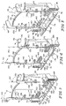
- Fig. 1 is a front perspective view of a seat including a seat shell, a base, a child-restraint harness coupled to the seat shell, and a harness-control panel movable up and down relative to the seat shell (in a position behind a child seated in the seat shell) by a panel-height adjustment mechanism (which includes two grips shown to extend above the harness-control panel) to adjust the height of shoulder belts of the child-restraint harness relative to a bottom seat portion of the seat shell to adapt the seat for use by both small-sized and large-sized children;
- Fig. 2 is a rear perspective view of the seat of Fig. 1 showing two shoulder belts of the child-restraint harness extending along a back side of the seat shell and engaging a horizontal belt-support bar of the adjustment mechanism which is shown to be positioned within a slot of a vertical bar-anchor member formed in the seat shell;
- Figs. 3-5 are rear perspective views, with portions broken away, of the harness-control panel and adjustment mechanism coupled to the panel showing rotational movement of two actuators of the adjustment mechanism to engage the belt-support bar and move the belt-support bar out of engagement with one of the slots (not shown) formed in the bar-anchor member (not shown);
- Fig. 6 is a sectional view of the seat of Figs. 1 and 2 taken along line 6-6 of Fig. 2 showing the child-restraint harness coupled to the seat shell and engaging the belt-support bar of the adjustment mechanism to restrain a child (shown in phantom) seated in the seat and showing the harness-control panel in a lowest one of four available positions (with the shoulder belts passing therethrough) and retained in such a position by the belt-support bar;
- Figs 7-9 are transverse sectional views, with portions broken away, taken along line 7-7 of Fig. 6 showing movement of a foot portion of one of the actuators to engage the belt-support bar and move the belt-support bar from a locked position within one of the position locator slots (not shown) to an unlocked position removed from one of the position locator slots;
- Fig. 10 is a sectional view taken along line 10-10 of Fig. 7 through a handle bar of the adjustment mechanism showing a first arm of the handle bar received within a cavity formed by a support arm of the harness-control panel and coupled to the harness-control panel by a screw so that the harness-control panel and handle bar move together in a generally vertical direction when the belt-support bar is removed from within one of the position locator slots;
- Fig. 11 is a front elevation view of an upper portion of the seat showing the harness-control panel in a lowest position relative to the seat shell;
- Fig. 12 is a rear elevation view of the upper portion of the seat shown in Fig. 11 showing the two shoulder belts, the belt-support bar, the handle bar (shown with portions broken away), and the slotted vertical center and outer support bar anchor members for receiving a portion of the belt-support bar;
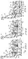
- Figs. 13-15 show a sequence of steps in which the belt-support bar is removed by a user from within one of the slots of the anchor member to raise the harness-control panel from a lowest position to a next highest position;
- Fig. 13 is a sectional view taken along line 13-13 of Fig. 12 showing the belt-support bar retained in the first slot formed in bar-anchor member;
- Fig. 14 is a sectional view similar to Fig. 13 showing upward movement of the harness-control panel relative to the seat shell after a user has pulled the belt-support bar to the right toward the handle bar to release the belt-support bar from the first slot in order to raise the handle bar and the belt-support bar together, thus raising the harness-control panel;
- Fig. 15 is a sectional view similar to Figs. 13 and 14 showing engagement of the belt-support bar in the second slot to establish a fixed raised position of the harness-control panel relative to the seat shell above the lowest position shown in Fig. 13 and showing the shoulder belts passing through the seat shell when the harness-control panel occupies its second position at a point that is higher than the seat shell entry point of the shoulder belts when the harness-control panel occupies its lowest position;
- Fig. 16 is a front elevation view similar to Fig. 11 showing the harness-control panel in its second position (corresponding to the position shown in Fig. 15);
- Fig. 17 is a rear elevation view similar to Fig. 12 showing the upper portion of the seat shown in Fig. 16 wherein the belt-support bar engages the second slot formed in the bar-anchor member;
- Fig. 18 is a front elevation view similar to Figs. 11 and 16 showing the harness-control panel in a third position raised above the second position shown in Fig. 16;
- Fig. 19 is a rear elevation view similar to Figs. 12 and 17 showing the upper portion of the seat shown in Fig. 18 wherein the belt-support bar engages a third slot formed in the bar-anchor member;
- Fig. 20 is a front elevation view similar to Figs. 11, 16 and 18 showing the harness-control panel in a fourth position and showing the two belt-receiving slots of the harness-control panel above vertical guide slots (shown in phantom) of the seat shell; and
- Fig. 21 is a rear elevation view similar to Figs. 12, 17 and 19 showing the belt-support bar engaged with a fourth slot of the bar-anchor member.
-
- A child-
restraint seat 10 is shown in Figs. 1 and 2 and is configured to be used on avehicle seat 12, as shown in Fig. 6. Child-restraint seat 10 includes a child-restraint harness 14 and a harness-control panel 16 designed to accommodate both younger, smaller children and older, larger children and is arranged to lie between aseat shell 18 ofseat 10 and achild 32 seated onseat 10.Seat 10 further includes a panel-height adjustment mechanism 19 coupled topanel 16 to movepanel 16 up and down relative toseat shell 18 in order to accommodate children of various sizes. - Panel-
height adjustment mechanism 19 includes a front-access means for movingpanel 16 up and down (as shown in Figs. 3-5) and a rear-access means for movingpanel 16 up and down (as shown in Figs. 13-15). Panel-height adjustment mechanism 19 as is discussed in more detail below. The front-access means allows a caregiver to adjust the height ofpanel 16 relative toseat shell 18 from afront side 21 ofseat 10 such as whenseat 10 in a forward facing position on vehicle seat 12 (as shown in Fig. 6), for example, while rear-access means allows the caregiver to adjust the height ofpanel 16 from a rear side 23 ofseat 10 such as whenseat 10 is in a rearward facing position onvehicle seat 12. -
Seat 10 further includes abase 20 and apivotable support leg 22, as shown in Figs. 1, 2, and 6. In addition to providing adjustable harness-control panel 16, which moves up and down relative toseat shell 18 to accommodate children of various sizes, child-restraint seat 10 can also be converted for use as a forward-facing seat or a rearward-facing seat to further accommodate children of various sizes. This conversion can be accomplished by movement ofseat shell 18 relative tobase 20 and/or by movement ofpivotable support leg 22 relative toseat shell 18. Althoughseat shell 18 is shown as a one-piece molded body in the illustrated embodiment, it is within the scope of this disclosure to use a multiple-piece body as well. -
Seat shell 18 includes abottom seat portion 24 to support a child's bottom and upper legs and aback support portion 26 positioned at an angle tobottom seat portion 24, as shown in Fig. 1. As shown, for example, in Figs. 13-15, harness-control panel 16 is movable up and downrelative seat shell 18 to adjust a height ofpanel 16 abovebottom seat portion 24 to accommodate larger as well as smaller children onseat 10. - First and second
side wall portions seat shell 18 lie on opposite sides ofbottom seat portion 24, as shown in Fig. 1, and generally prevent lateral movement of a child 32 (shown in phantom in Fig. 6) inseat 10. A cushion or seat cover (not shown) can cover portions ofseat shell 18 including bottom seat portion portion, back support portion, and/or first and secondside wall portions - As mentioned above,
harness 14 is provided to restrain a child's movement relative toseat shell 18.Harness 14 includesshoulder belts lower belt 38, and abuckle unit 40, as shown in Figs. 1 and 6. A harness-retainer 42 is used to holdshoulder belts lower belt 38 is coupled toshoulder belts junction member 44 and another end oflower belt 38 is coupled toseat shell 18 by a belt-adjustment mechanism 46, as shown in Fig. 6.Buckle unit 40 includes aframe 48 selectively coupled to aconnector 50 onbottom seat portion 24, afirst buckle 52 couplingfirst shoulder belt 34 toframe 48, and asecond buckle 54 couplingsecond shoulder belt 36 toframe 48.Seat 10 can be adapted to receive other styles of harnesses (not shown) and a combination of a harness and a movable barrier shield (not shown). - Harness-
control panel 16 is positioned in a child-receivingspace 56 defined in a front portion orfront side 21 ofseat 10 and is mounted for up-and-down movement relative tobottom seat portion 24 ofseat 10, as shown best in Figs. 13-15. Up-and-down movement ofpanel 16 functions to raise and lower the "height" ofshoulder belts bottom seat portion 24 to adaptseat 10 to accommodate young, small-sized children or older, larger-sized children. -
Panel 16 includes aback plate 58 having shoulder belt-receivingslots headrest 64 in an upper portion ofback plate 58 generally aboveslots Panel 16 also includes upper andlower wing members back plate 58 and positioned in spaced-apart relation to one another. Illustratively, each of the upper andlower wing members plate 58 as shown, for example, in Fig. 1. Illustrativelower wing members 68 are removable fromback plate 58, as shown, for example, in Figs. 11, 16, 18, and 20. Up-and-down movement ofpanel 16 also functions to raise and lower the height ofheadrest 64 abovebottom seat portion 24 to adaptseat 10 to accommodate children of various ages and sizes. As shown, for example, in Figs. 13-19,shoulder belts headrest 64 move up and down together relative toseat shell 18 to assure proper shoulder belt fit for a child seated inseat 10. - As shown best in Figs. 3-5,
panel 16 further includes first andsecond support arms 70 coupled to arear side 134 of bothback plate 58 andupper wing members 66.Arms 70 are spaced apart from one another and extend away fromrear side 134 ofback plate 58. Eacharm 70 defines acavity 72 for receiving a portion of the panel-height adjustment mechanism 19 therein to couplepanel 16 andmechanism 19 together, as is discussed in more detail below. -
Back support portion 26 ofseat shell 18 and backplate 58 ofpanel 16 cooperate to set a nominal height 74 (see Fig. 6) of first andsecond shoulder belts bottom seat portion 24 ofseat shell 18. A caregiver can raise andlower panel 16 easily to change the height of first andsecond shoulder belts height adjustment mechanism 19 ofseat 10. As mentioned above, panel-height adjustment mechanism 19 may be operated from both thefront side 21 ofseat 10 and the rearside 23of seat 10 to move panel 16 (withshoulder belts 34, 36) up and down relative toseat shell 18. -
Adjustment mechanism 19 includes two bar actuators 76 (shown best in Figs. 3-5 and shown extending abovepanel 16 in Figs. 1 and 2) coupled topanel 16, a belt-support bar 78 (also shown best in Figs. 3-5), and a handle bar 80 (shown in Fig. 2 and Figs. 7-9) coupled topanel 16 as well. Additional features and operation of theadjustment mechanism 19 are discussed in greater detail below. Generally, however, actuators 76 are accessible by a caregiver fromfront side 21 ofseat 10, whilehandle bar 80 and belt-support bar 78 are each accessible by a caregiver from rear side 73 ofseat 10. -
Back support portion 26 includes twovertical channels channels 82 are aligned in spaced-apart relation to lie "behind" backplate 58 ofpanel 16 sofirst shoulder belt 34 can pass throughfirst channel 82 andsecond shoulder belt 36 can pass throughsecond channel 84. As mentioned before,panel 16 includes a pair of spaced-apart horizontally extending, elongated belt-receivingslots -
First slot 60 is sized to receive a portion offirst shoulder belt 34 and to allow the portion offirst shoulder belt 34 to also pass throughfirst channel 82.First channel 82, formed inback support portion 26, is arranged to lie in communication with belt-receivingslot 60 formed inpanel 16 to enable movement of a portion offirst shoulder belt 34 inslot 60 andfirst channel 82 during up and down movement ofpanel 16 relative toseat shell 18. - Similarly,
second slot 62 is sized to receive a portion ofsecond shoulder belt 36 and to allow the portion ofsecond shoulder belt 36 to also pass throughsecond channel 84.Second channel 84, formed inback support portion 26, arranged to lie in communication with belt-receivingslot 62 formed inpanel 16 to enable movement of a portion ofsecond shoulder belt 36 inslot 62 andsecond channel 84 during up and down movement ofpanel 16 relative toseat shell 18. - The height of
panel 16 abovebottom seat portion 24 determines the nominal height 74 (i.e.seat shell 18 entry point) of the first andsecond shoulder belts Seat 10 can be adjusted to accommodate young, small-sized children by movingpanel 16 to its lowest position shown, for example, in Figs. 1, 11, and 12 to minimizenominal height 74 and cause the seat shell entry points ofshoulder belts harness 14 will be used to restrain a young, small-sized child 32 seated in child-restraint seat 10, as shown in Fig. 6. Child-restraint seat 10 can also be adjusted to assume other positions to accommodate somewhat older, larger children in child-restraint seat 10 by raisingpanel 16 upwardly relative to backsupport portion 26 ofseat shell 18 to increasenominal height 74 and cause the seat shell entry point ofshoulder belts shoulder belts 34, 36) is raised up and down by panel-height adjustment mechanism 19, accessible to a caregiver from both thefront side 21 and rear side 23 ofseat 10. - Child-
restraint seat 10 can also be adjusted to accommodate even older, larger-sized children by movingpanel 16 to its highest position shown, for example, in Figs. 20 and 21. In this position, it is contemplated thatharness 14 will be removed from child-restraint seat 10 (or tucked in an out-of-the-way, unused position) and that an adult three-point vehicle lap/shoulder belt (not shown) will be used to restrain a child seated in child-restraint seat 10. In its highest position, harness-control panel 16 is used primarily to supportheadrest 64 in a proper elevated position relative tobottom seat portion 24.Panel 16 is not used to control the seat shell entry points ofshoulder belts restraint seat 10 in such a configuration. As such, first belt-receivingslot 60 does not communicate withfirst channel 82 and second belt-receivingslot 62 does not communicate withsecond channel 84 whenpanel 16 and itsheadrest 64 is positioned in its highest position. - As mentioned before, panel-
height adjustment mechanism 19 includesactuators 76 each coupled topanel 16, belt-support bar 78, and handlebar 80 also coupled topanel 16. Belt-support bar 78 is movably coupled to handlebar 80 and is therefore coupled topanel 16 throughhandle bar 80.Actuators 76 rotate relative topanel 16 to engage belt-support bar 78, as shown in Figs. 3-5.Mechanism 19 further includes a pair ofsprings 86 each coupled to both handlebar 80 and belt-support bar 78. Handlebar 80 includes spaced-apartarms 88 each received withincavity 72 of the respectively alignedsupport arm 70 ofpanel 16, as shown in Figs. 7-9, for up and down movement therewith. Eacharm 88 is secured topanel 16 by ascrew 90, as shown in Fig. 10. Handlebar 80 further includes agrip member 92 coupled to and positioned to extend between spaced-apartarms 88. - Each
arm 88 ofhandle bar 80 passes through a respectivevertical guide slot 94 formed inback support portion 26 ofseat shell 18.Guide slots 94 are formed inback support portion 24 ofseat shell 18 and lie in spaced-apart, parallel relation to one another. Each arm 88 (coupled to arespective support arm 70 of panel 16) reciprocates in eachrespective guide slot 94 aspanel 16 moves up and down relative to backsupport portion 24 between a lowest position (shown, for example, in Figs. 1, 11, and 12) adapted to suit a young, small-sized child and a highest position (shown, for example, in Figs. 20 and 21) adapted to suit an older, larger-sized child. - Each
arm 88 ofhandle bar 80 includes aguide channel 96, as shown in Fig 10. Belt-support bar 78 is received within eachguide channel 96 so that belt-support bar 78 is coupled to and positioned to extend between spaced-apartarms 88 ofhandle bar 80. Further, belt-support bar 78 is slidably movable within guide channels 96 (relative to handle bar 78) in a generally horizontal direction toward or away fromback support portion 26 ofseat shell 18. - As shown in Fig. 10, each
arm 88 includes aspring mount 98 for receiving one end of one of the tension springs 86 of panel-height adjustment mechanism 19. Eachtension spring 86 is coupled to and positioned to extend between therespective spring mount 98 and belt-support bar 78. Tension springs 98 function to normally bias belt-support bar 78 in a locked position in engagement withseat shell 12 as shown in Figs. 6, 7, 10, and 13. While the figures show thesprings 98 to be tension springs, one could use compression springs located between belt-support bar 78 andgrip member 92 of thehandle bar 80 as well. -
Seat shell 18 further includes a center vertical bar-anchor member 100 coupled to a rear side ofback support portion 26 to lie in aspace 110 midway between first and second verticalback ribs seat shell 18. An upper end of bar-anchor member 100 is coupled to a mid-portion of a horizontalback rib 118, as shown in Fig. 2. Bar-anchor member 100 includes a plurality of panel height locators such as vertically spaced-apart slots (e.g. slots support bar 78 therein to establish a fixed or locked position of belt-support bar 78, handlebar 80 andpanel 16 relative to the underlyingbottom seat portion 24 ofseat shell 18. - Belt-
support bar 78 is received within one of the slots, 122, 124, 126, or 128 when in the locked position.Slot 122 is located to define a "lowest" position of harness-control panel 16 as shown in Figs. 11-13.Slot 124 is located to define a "middle" position of harness-control panel 16 as shown in Figs. 16 and 17.Slot 126 is located to define a "high" position of harness-control panel 16 as shown in Figs. 18 and 19.Slot 128 is located to define a "highest" position of harness-control panel 16, as shown in Figs. 20 and 21, wherein an older, larger sized child is restrained in child-restraint seat 10 using an adult vehicle shoulder and lap belt assembly rather than using child-restraint harness 14 provided in child-restraint seat 10. - A pair of outer vertical bar-
anchor members 112 ofseat shell 18 are also coupled to the rear side ofback support portion 26 to lie inspace 110 in spaced-apart relation to each other so that center vertical bar-anchor member 100 is positioned between the outer bar-anchor members 112. Similar to center bar-anchor member 100, an upper end of each outer bar-anchor member 112 is coupled to an outer end of horizontalback rib 118. Each outer bar-anchor member 112 further includes a plurality of panel height locators such as vertically spaced-apart slots (e.g. slots support bar 78 therein. The vertically spaced-apartslots anchor member 112 correspond to the vertically spaced-apartslots anchor member 100. - As mentioned above, each
arm 88 ofhandle bar 80 includesguide channel 96 for receiving one end (or a portion) of belt-support bar 78 therein and for supporting belt-support bar 78 for back-and-forth sliding movement relative to handlebar 80 as belt-support bar 78 is moved into and out of any of theslots anchor member 100 andslots anchor members 112 during movement of harness-control panel 16 relative toseat shell 18.Springs 86 are arranged to urge belt-support bar 78 in a direction towardback support portion 26 ofseat shell 18 to cause belt-support bar 78 to be retained in one of theslots anchor member 100 upon movement of belt-support bar 78 into such a slot. Therefore, belt-support bar 78 is normally retained in the locked position and thus acts as a locking member for panel-height adjustment mechanism 19. In other words, it is not necessary for locking member or belt-support bar 78 to supportshoulder belt portions restraint harness 14, although, in the illustrative embodiments belt-support bar 78 is shown to do so. It is within the scope of this disclosure foradjustment mechanism 19 to include any suitable type of locking member or locking means to preventing thepanel 16 from moving up and down relative toseat shell 18. - As mentioned above, panel-
height adjustment mechanism 19 permits a user to adjust the height of panel 16 (andshoulder belts 34, 36) relative tobottom seat portion 24 ofseat shell 18 in order to accommodate children of various sizes. Further as mentioned above, panel-height adjustment mechanism 19 ofseat 10 includes a front-access means of adjusting the height ofpanel 16 and a rear-access means of adjusting the height ofpanel 16. Specifically, panel-height adjustment mechanism 19 is accessible by a user fromfront side 21 ofseat 10 and from rear side 23 ofseat 10 so that the height ofpanel 16 may be adjusted whenseat 10 is in either a forwardly-facing position on vehicle seat 12 (as shown, for example, in Fig. 6) or a rearwardly-facing position on vehicle seat 12 (not shown). More specifically, belt-support bar 78 of panel-height adjustment mechanism may be moved to an unlocked position disengaged from one of the panel-height locater slots seat 10. - Illustratively, the front-access means of adjusting
panel 16 includesactuators 76 and belt-support bar or lockingmember 78. Looking now to Figs. 3-5, each actuator 76 includes agrip 130 anelongated rod 132 coupled togrip 130, and afoot portion 146 coupled torod 132.Actuators 76 are coupled to arear side 134 ofpanel 16 for up and down movement withpanel 16.Actuators 76 are therefore positioned adjacent a front surface ofback support portion 26. Eachrod 132 is received within first andsecond clips panel 16 and is further guided byguides 140. Eachfoot portion 146 is coupled to oneend 148 ofrod 132.Grip 130 of each actuator 76 is coupled to anopposite end 150 of therespective rod 132.Foot portion 146 is generally positioned at approximately a 90 degree angle tovertical rod 132. Illustratively,foot portion 146 includes afirst portion 152 coupled toelongated rod 132, asecond portion 154 coupled tofirst portion 152, and athird portion 156 coupled tosecond portion 154. Asactuators 76 are rotated,foot portion 146 engages belt-support bar 78 to move belt-support bar 78 out of engagement with one of theslots Foot portion 146 of each actuator 76 is rotated through respectivevertical channels back support portion 26 in order to engage belt-support bar 78. - As shown in Figs. 1 and 2,
grip 130 of each actuator 76 extends abovepanel 16 so that eachgrip 130 is visible and accessible to a user fromfront side 21 ofseat 10. It is contemplated thatactuators 76 or similar actuating mechanisms may be positioned in other ways in order to be accessible to a caregiver fromfront side 21 ofseat 10. Eachactuator 76 is rotatable about avertical axis 142 extending along eachelongated rod 132, as shown in Figs. 1-3. In operation, a caregiver grasps eachgrip 130 and rotates eachgrip 130 toward the center ofseat 10. Normally, each grip extends outwardly away from the center ofseat 10, as shown in Fig. 1. Eachgrip 130 is coupled tocorresponding rod 132 so that each rod 132 (along with each foot portion 146) is rotated aboutaxis 142 as well. Illustratively, as viewed from above, the right actuator 76 (looking at Figs. 3-5) is rotated in a counter-clockwise direction while theleft actuator 76 is rotated in a clockwise direction. It is within the scope of this disclosure to providedactuators 76 which rotate in either direction. - As each
rod 132 is rotated about eachaxis 142, therespective foot portions 146 engage belt-support bar 78 and act against the bias ofsprings 86 to move belt-support bar 78 from the engaged position to the disengaged position to unlock or releasepanel 16 so that panel 16 (withshoulder belts 34, 36) may be moved up and down relative tobottom seat portion 24. As shown in Figs. 3-5,third portion 156 of eachfoot portion 146 engages belt-support bar 78, although, it is within the scope of this disclosure for any portion of eachfoot portion 146 to engage belt-support bar 78. Once belt-support bar 78 has been moved to the disengaged position and is held there by eachfoot portion 146, the user may continue to graspgrips 130 and movepanel 16 up and down because, as stated above, eachlever 76 is coupled topanel 16 for up and down movement therewith. Oncepanel 16 is at the desired height, user may rotate eachlever 76 in the opposite direction to allow belt-support bar 78 to be biased towardback support portion 26 and into any one of the panel-height locator slots 122, 124,126, 128 desired. - The rear-access means of adjusting the height of
panel 16 up and down relative tobottom seat portion 24 includeshandle bar 80 and belt-support bar 78 of panel-height adjustment mechanism 19. Handlebar 80, as mentioned before, includes spaced-apartarms 88 coupled corresponding support arms orposts 70 ofpanel 16 andgrip member 92 interconnectingarms 88. Becausehandle bar 80 is rigidly coupled topanel 16, handlebar 80 is urged to move generally vertically withpanel 16 relative toseat shell 18. Handlebar 80 is provided as a support so that a user can grip belt-support bar 78 andgrip member 92 ofhandle bar 80 to move belt-support bar 78 relative to bar-anchor members grip member 92 against the bias ofsprings 86 to release belt-support bar 78 fromslot 122, for example, as shown in Figs. 13-15. - Once belt-
support bar 78 is released from engagement withslot 122, panel-height adjustment mechanism 19 with harness-control panel 16 is movable up or down to engage one of theother slots anchor member 100. Figs. 13-15, for example, illustrate the movement of panel-height adjustment mechanism 19 from the first lowest position wherein belt-support bar 78 is received withinslot 122 to the second middle position wherein belt-support bar 78 is received withinslot 124. As shown in the drawings,shoulder belts slots support bar 78 to lie on belt-support bar 78 on opposite sides of center bar-anchor member 100 so that any raising or lowering of belt-support member 100 relative to center and outer bar-anchor members second shoulder belts panel 16 are provided to guide eachshoulder belt support bar 78 after being received though respective belt-receivingslots surface 134 ofback plate 58 and are positioned below eachrespective slot - Although this disclosure has been described in detail with reference to certain embodiments, variations and modifications exist within the scope and spirit of the disclosure as described and defined in the following claims.
Claims (16)
- A child-restraint seat comprisinga seat shell including a bottom seat portion and a back support portion including a channel formed therein, the seat shell being adapted to be coupled to a vehicle seat by a seat anchor coupled to the vehicle,a child-restraint harness coupled to the seat shell,a harness-control panel including a belt-receiving opening receiving a shoulder belt portion of the child-restraint harness, the harness-control panel being mounted on the seat shell outside the channel for up and down movement relative to the seat shell to raise and lower the shoulder belt portion of the child-restraint harness with respect to the bottom seat portion, anda panel-height adjustment mechanism coupled to the harness-control panel and movable between a locked position to prevent the harness-control panel from moving up and down relative to the seat shell and an unlocked position to allow the harness-control panel to move up and down relative to the seat shell, an actuator coupled to the panel-height adjustment mechanism and positioned forward a front surface of the back support portion and operable to permit locking and unlocking from a front side of the child-restraint seat when the seat is facing forward and is coupled to a vehicle seat by the seat anchor, and a locking member of the panel-height adjustment mechanism being positioned adjacent a rear surface of the back support portion to be accessible to a user from a rear side of the child-restraint seat, the actuator being movable relative to the harness-control panel between a first unlocked position outside the channel formed in the back support portion and a second locked position within the channel of the back support portion.
- The child-restraint seat of claim 1, wherein the harness-control panel is positioned to lie adjacent to a front surface of the back support portion to cause a child seated in the seat shell to rest against the harness-control panel.
- The child-restraint seat of claim 1, wherein the locking member is coupled to the harness-control panel and is engaged with the seat shell when the panel-height adjustment mechanism is in the locked position and disengaged from the seat shell when the panel-height adjustment mechanism is in the unlocked position.
- The child-restraint seat of claim 3, wherein the locking member is biased to engage the seat shell.
- The child-restraint seat of claim 4, wherein the panel-height adjustment mechanism includes panel-height locators provided in the back support portion and formed to receive the locking member therein when the panel-height adjustment mechanism is in the locked position.
- The child-restraint seat of claim 4, wherein the shoulder belt portion of the child-restraint harness engages the locking member and is supported for up-down movement with the harness-control panel on the locking member.
- The child-restraint seat of claim 3, wherein the actuator of the panel-height adjustment mechanism is coupled to the harness-control panel for up and down movement therewith, and wherein the actuator is movable relative to the harness-control panel to disengage the locking member from the seat shell to move the panel-height adjustment mechanism to the unlocked position.
- The child-restraint seat of claim 7, wherein the actuator includes a grip, a rod coupled to the grip, and a foot portion coupled to the rod, and wherein the grip extends above the harness-control panel and is accessible by a user from the front side of the child-restraint seat.
- The child-restraint seat of claim 8, wherein the foot portion lies at an angle to the rod and is positioned for engagement with the locking member when the actuator is rotated.
- The child-restraint seat of claim 7, wherein the panel-height adjustment mechanism includes another actuator coupled to the harness-control panel, and wherein the actuators are spaced-apart from each other.
- The child-restraint seat of claim 3, wherein the panel-height adjustment mechanism further includes a handle coupled to the harness-control panel for up and down movement therewith, and wherein the locking member is a bar slidably coupled to the handle for movement in a generally horizontal direction toward and away from the back support portion of the seat shell, and further wherein the handle and the bar are each accessible by a user from the rear side of the seat.
- The child-restraint seat of claim 11, wherein the handle includes a support arm coupled to the harness-control panel, and wherein the support arm includes a channel for receiving at least a portion of the bar for back and forth movement of the bar within the channel relative to the handle and the harness-control panel.
- The child-restraint seat of claim 12, wherein the bar is biased toward the back support portion of the seat shell.
- The child-restraint seat of claim 3, wherein the locking member is a bar extending generally horizontally across at least a portion of the back support portion, and further wherein the shoulder belt portion of the child-restraint harness is supported on the bar for up and down movement therewith.
- The child-restraint seat of claim 1, wherein the panel-height adjustment mechanism includes a locking member coupled to the harness-control panel and normally engaged with a portion of the seat shell to retain the panel-height adjustment mechanism in the locked position, and an actuator coupled to the harness-control panel, accessible to a user from the front side of the seat, and movable relative to the harness-control panel to move the locking member to a position disengaged from the seat shell.
- A juvenile vehicle seat comprisinga seat shell,a headrest coupled to the seat shell for up and down movement relative to the seat shell,a child-restraint harness coupled to the seat shell and having a shoulder belt portion coupled to the headrest for up and down movement of the shoulder belt portion with the headrest relative to the seat shell,locking means rearward of the back support portion for preventing up and down movement of the headrest relative to the seat shell, andunlocking means forward of the back support portion for allowing up and down movement of the headrest relative to the seat shell, the unlocking means being positioned adjacent a front surface of the seat shell and accessible to a user from a front side of the seat shell.
Applications Claiming Priority (2)
| Application Number | Priority Date | Filing Date | Title |
|---|---|---|---|
| US330812 | 2002-12-27 | ||
| US10/330,812 US6779843B2 (en) | 2002-12-27 | 2002-12-27 | Harness-control panel adjuster for child-restraint seat |
Publications (1)
| Publication Number | Publication Date |
|---|---|
| EP1433653A2 true EP1433653A2 (en) | 2004-06-30 |
Family
ID=32469048
Family Applications (1)
| Application Number | Title | Priority Date | Filing Date |
|---|---|---|---|
| EP03258193A Withdrawn EP1433653A2 (en) | 2002-12-27 | 2003-12-23 | Harness-control panel adjuster for child-restraint seat |
Country Status (3)
| Country | Link |
|---|---|
| US (1) | US6779843B2 (en) |
| EP (1) | EP1433653A2 (en) |
| CA (1) | CA2454191C (en) |
Cited By (10)
| Publication number | Priority date | Publication date | Assignee | Title |
|---|---|---|---|---|
| EP1754624A2 (en) | 2005-08-18 | 2007-02-21 | Takata Corporation | Child seat |
| NL1032549C2 (en) * | 2006-09-21 | 2008-03-25 | Maxi Miliaan Bv | High chair. |
| GB2444834A (en) * | 2006-12-12 | 2008-06-18 | Wonderland Nursery Goods | Vehicle child seat allowing combined vertical adjustment of headrest and harness support |
| EP1870279A3 (en) * | 2006-06-13 | 2009-04-01 | Georg Ludwig Kunz | Child car seat |
| NL1035742C2 (en) * | 2008-07-23 | 2010-01-26 | Maxi Miliaan Bv | Tub suitable for a child vehicle seat as well as such a child vehicle seat. |
| EP2208637A1 (en) * | 2009-01-15 | 2010-07-21 | Dorel France Sa | Juvenile vehicle seat with headrest-height controller |
| NL1036865C2 (en) * | 2009-04-16 | 2010-10-19 | Maxi Miliaan Bv | Child vehicle seat. |
| CN103507672A (en) * | 2012-05-09 | 2014-01-15 | 宝得适儿童用品有限公司 | Child safety seat with improved recline base and adjustable headrest |
| EP2329985B1 (en) | 2009-12-07 | 2018-05-16 | Wonderland Switzerland AG | Child car seat |
| CN109263522A (en) * | 2017-07-18 | 2019-01-25 | 宝得适罗姆儿童安全有限公司 | Seat belt fastening system for use with child safety seats |
Families Citing this family (46)
| Publication number | Priority date | Publication date | Assignee | Title |
|---|---|---|---|---|
| FR2858787B1 (en) * | 2003-08-13 | 2005-10-21 | Ampafrance | CAR SEAT FOR RECLINING CHILD AND SWIVEL BETWEEN TRAVEL POSITION AND INSTALLATION POSITION |
| JP2007508181A (en) * | 2003-10-10 | 2007-04-05 | インディアナ・ミルズ・アンド・マニュファクチャリング・インコーポレーテッド | Vehicle safety restraint system |
| USD504583S1 (en) * | 2003-12-09 | 2005-05-03 | Recaro Gmbh & Co. Kg | Restraint for a child's seat |
| US7055903B2 (en) * | 2004-01-09 | 2006-06-06 | Cosco Management, Inc. | Adjustor for juvenile vehicle seat |
| US7246852B2 (en) * | 2004-03-10 | 2007-07-24 | Cosco Management, Inc. | Headrest actuator for juvenile vehicle seat |
| US8282165B2 (en) * | 2004-04-28 | 2012-10-09 | Recaro Child Safety Gmbh & Co. Kg | Reboard system |
| DE102004020902A1 (en) * | 2004-04-28 | 2005-12-01 | Recaro Gmbh & Co. Kg | Baby Seat |
| EP1778517A2 (en) * | 2004-06-29 | 2007-05-02 | Kidnetik Corp. | Child restraint apparatus for a vehicle cross-reference to related applications |
| NL1026769C2 (en) * | 2004-08-02 | 2006-02-06 | Maxi Miliaan Bv | Seat belt guidance mechanism and child vehicle seat. |
| US7246854B2 (en) * | 2004-10-15 | 2007-07-24 | Indiana Mills & Manufacturing Inc | Child vehicle seat having an adjustable harness system |
| WO2007003918A1 (en) * | 2005-07-01 | 2007-01-11 | Britax Excelsior Limited | Child safety seat |
| ES1061044Y (en) * | 2005-09-12 | 2006-04-01 | Jane Sa | CHILD SEAT FOR CARS. |
| US7232185B2 (en) * | 2005-09-15 | 2007-06-19 | Wonderland Nursery Goods Co., Ltd. | Adjustable head rest for child car seat |
| US7463161B2 (en) * | 2005-12-02 | 2008-12-09 | Delphi Technologies, Inc. | Child restraint system with child seat monitoring system and method for monitoring a child seat |
| US7527335B2 (en) * | 2006-02-27 | 2009-05-05 | Steelcase Inc. | Seating unit with adjustable components |
| US7901003B2 (en) * | 2006-06-30 | 2011-03-08 | Meeker R & D, Inc. | Juvenile convertible car seat |
| US7452031B2 (en) * | 2006-11-10 | 2008-11-18 | Evenflo Company, Inc. | Multi-adjustable child seat with detachable softgoods attachment |
| US7547065B2 (en) * | 2007-02-23 | 2009-06-16 | Evenflo Company, Inc. | Child vehicle seat with harness adjustment mechanism |
| AU2008201394A1 (en) * | 2007-04-23 | 2008-11-06 | Phil And Teds Most Excellent Buggy Company Limited | Strap Support Apparatus |
| US20090127902A1 (en) * | 2007-11-19 | 2009-05-21 | Meeker R&D, Inc. | Child's Car Seat Harness Storage System |
| US8632127B2 (en) | 2008-12-23 | 2014-01-21 | Graco Children's Products Inc. | Child safety seat with height adjustable harness |
| US8342604B2 (en) * | 2009-02-04 | 2013-01-01 | Cosco Management, Inc. | Juvenile vehicle seat with seat-back channel cover |
| FR2946294B1 (en) * | 2009-06-04 | 2011-06-17 | Dorel France Sa | CHILDREN'S CAR SEAT |
| US8226162B2 (en) * | 2009-09-11 | 2012-07-24 | Campbell Corey A | Child safety seat |
| FR2955535A1 (en) * | 2010-01-28 | 2011-07-29 | Dorel France Sa | CHILD CAR SEAT, INTENDED TO BE SOLIDARIZED AT THE SEAT OF A MOTOR VEHICLE. |
| US8550555B2 (en) * | 2010-05-04 | 2013-10-08 | Cosco Management, Inc. | Child restraint for vehicle |
| CN201882129U (en) * | 2010-11-18 | 2011-06-29 | 中山市隆成日用制品有限公司 | Safety shoulder belt adjusting mechanism for seat of baby carrier |
| US20120326476A1 (en) * | 2011-02-08 | 2012-12-27 | Graco Children's Products Inc. | Child Car Seat and Adjustable Head Support |
| US9579996B2 (en) * | 2011-03-22 | 2017-02-28 | Dorel Juvenile Group, Inc. | Infant holder for vehicle seat |
| CA2849534C (en) * | 2011-09-22 | 2020-01-07 | Clek Inc. | Child safety seat |
| AU2013100453A4 (en) | 2012-05-09 | 2013-05-23 | Britax Child Safety, Inc. | Flip forward buckle assembly |
| EP2666664B1 (en) * | 2012-05-22 | 2014-04-02 | HAUCK GmbH & Co. KG | Child safety seat for vehicles |
| US9371017B2 (en) | 2012-07-03 | 2016-06-21 | Kids Ii, Inc. | Pivotal handle lock/release mechanism for child car seat |
| CN203110980U (en) * | 2013-01-19 | 2013-08-07 | 麦克英孚(宁波)婴童用品有限公司 | Automotive child safety seat with height-adjustable headrest |
| US9381834B2 (en) * | 2013-03-21 | 2016-07-05 | Wonderland Nurserygoods Company Limited | Child safety seat |
| US20150035329A1 (en) * | 2013-07-30 | 2015-02-05 | Recaro Child Safety Llc | Seat with automatic harness strap adjustment mechanism |
| CN105196897A (en) * | 2015-09-24 | 2015-12-30 | 无锡利凯儿童用品有限公司 | Child safety seat for passenger car |
| CN105216663A (en) * | 2015-09-24 | 2016-01-06 | 无锡利凯儿童用品有限公司 | The head rest adjusting device of riding child's safety seat for vehicle |
| CN108340815B (en) * | 2017-01-22 | 2023-06-30 | 东莞金旺儿童用品有限公司 | child safety seat |
| EP3590757B1 (en) * | 2017-09-06 | 2021-04-21 | BRITAX RÖMER Kindersicherheit GmbH | Child safety seat with headrest height adjustment mechanism |
| US10843605B2 (en) * | 2018-05-10 | 2020-11-24 | Dorel Juvenile Group, Inc. | Headrest-height adjuster for juvenile seat |
| CN110697051B (en) * | 2019-09-25 | 2021-05-04 | 湖北航宇嘉泰飞机设备有限公司 | Height adjusting mechanism for shoulder strap outlet of aviation seat |
| US11124095B2 (en) * | 2019-09-27 | 2021-09-21 | Evenflo Company, Inc. | Car seat harness removal system |
| US12472853B2 (en) | 2021-10-21 | 2025-11-18 | Dorel Juvenile Group, Inc. | Child restraint |
| US20250042313A1 (en) * | 2023-08-01 | 2025-02-06 | Graco Children's Products Inc. | Child restraint system including internal side impact surfaces |
| CN120439903A (en) * | 2024-02-07 | 2025-08-08 | 明门(中国)幼童用品有限公司 | Child safety seat |
Family Cites Families (27)
| Publication number | Priority date | Publication date | Assignee | Title |
|---|---|---|---|---|
| US4040664A (en) | 1975-08-28 | 1977-08-09 | American Safety Equipment Corporation | Harness anchoring for child safety seat |
| US4047755A (en) | 1976-03-22 | 1977-09-13 | Quentin H. McDonald | Restraining means for an infant car seat |
| US4342483A (en) | 1980-03-24 | 1982-08-03 | Juichiro Takada | Child safety seat for vehicles |
| US4376551A (en) | 1980-03-31 | 1983-03-15 | Questor Corporation | Child care seat and restraining system |
| EP0105973B1 (en) | 1982-10-08 | 1986-01-29 | B.V. Machine- en metaalwarenfabriek DREMEFA | Safety autocar chair for children |
| GB2143727B (en) * | 1983-07-26 | 1986-11-12 | Wall Ltd Howard | Improvements in or relating to a child's safety seat |
| JPS60189447U (en) | 1984-05-28 | 1985-12-16 | アップリカ葛西株式会社 | Child safety seat for automobiles |
| ES286732Y (en) | 1985-04-24 | 1987-01-16 | Play,S.A. | TILTING CHAIR |
| US4858997A (en) | 1986-12-31 | 1989-08-22 | Shubin Steven A | Child safety car seat |
| GB8709141D0 (en) | 1987-04-15 | 1987-05-20 | Britax Excelsior | Child's seat |
| US4915446A (en) | 1987-05-26 | 1990-04-10 | Darling Ronald J | Infant seat, removable seat and seat latch |
| GB8801716D0 (en) | 1988-01-26 | 1988-02-24 | Britax Excelsior | Child's safety seat |
| US5082325A (en) | 1990-07-20 | 1992-01-21 | Century Products Company | Harness adjustment mechanism |
| US5181761A (en) | 1991-09-12 | 1993-01-26 | Lisco, Inc. | Child restraint system |
| JPH07108635B2 (en) | 1991-12-05 | 1995-11-22 | タカタ株式会社 | Restraint protection sheet for infants |
| US5335964A (en) | 1992-10-13 | 1994-08-09 | Century Products Company | Automobile infant restraint seat |
| JP3299801B2 (en) | 1993-01-28 | 2002-07-08 | タカタ株式会社 | Infant restraint protection sheet |
| GB2282321A (en) | 1993-10-02 | 1995-04-05 | Britax Excelsior | Child safety seat with belt stowage |
| US5468046A (en) | 1994-07-13 | 1995-11-21 | Hoover Universal, Inc. | Seat belt mounting for integral child seat |
| US5580126A (en) | 1994-11-04 | 1996-12-03 | Century Products Company | Five-point booster car seat belt system |
| FR2735082B1 (en) | 1995-06-07 | 1998-06-05 | Ampafrance | CHILD SEAT |
| US6030047A (en) | 1998-04-06 | 2000-02-29 | Cosco, Inc. | Child vehicle seat with child-restraint harness adjustment mechanism |
| US6155638A (en) * | 1998-07-28 | 2000-12-05 | Fisher-Price, Inc. | Child restraint seat having amplified motion harness adjuster |
| US6189970B1 (en) | 1999-02-26 | 2001-02-20 | Cosco Management, Inc. | Harness for juvenile vehicle seat |
| US6491348B1 (en) | 2000-07-31 | 2002-12-10 | Cosco Management, Inc. | Child vehicle seat with child-restraint harness adjustment mechanism |
| US6623074B2 (en) * | 2001-04-05 | 2003-09-23 | Mattel, Inc. | Vehicle seat |
| US6695412B2 (en) * | 2001-06-20 | 2004-02-24 | Evenflo Company, Inc. | Car seat with adjustable harness |
-
2002
- 2002-12-27 US US10/330,812 patent/US6779843B2/en not_active Expired - Lifetime
-
2003
- 2003-12-23 EP EP03258193A patent/EP1433653A2/en not_active Withdrawn
- 2003-12-23 CA CA002454191A patent/CA2454191C/en not_active Expired - Fee Related
Cited By (22)
| Publication number | Priority date | Publication date | Assignee | Title |
|---|---|---|---|---|
| EP1754624A3 (en) * | 2005-08-18 | 2009-04-29 | Takata Corporation | Child seat |
| EP1754624A2 (en) | 2005-08-18 | 2007-02-21 | Takata Corporation | Child seat |
| EP1870279A3 (en) * | 2006-06-13 | 2009-04-01 | Georg Ludwig Kunz | Child car seat |
| NL1032549C2 (en) * | 2006-09-21 | 2008-03-25 | Maxi Miliaan Bv | High chair. |
| EP1902897A1 (en) * | 2006-09-21 | 2008-03-26 | Maxi Miliaan B.V. | Child seat |
| DE102007059667B4 (en) * | 2006-12-12 | 2011-04-14 | Wonderland Nurserygoods Co., Ltd. | Car seat for carrying a child in a motor vehicle |
| DE102007063746B4 (en) * | 2006-12-12 | 2015-04-02 | Wonderland Nurserygoods Co., Ltd. | Car seat |
| GB2444834A (en) * | 2006-12-12 | 2008-06-18 | Wonderland Nursery Goods | Vehicle child seat allowing combined vertical adjustment of headrest and harness support |
| GB2444834B (en) * | 2006-12-12 | 2011-12-14 | Wonderland Nursery Goods | Head rest and harness adjustment for child car seat |
| EP2147818A1 (en) * | 2008-07-23 | 2010-01-27 | Maxi Miliaan B.V. | A bucket suitable for a child vehicle seat as well as such a child vehicle seat |
| NL1035742C2 (en) * | 2008-07-23 | 2010-01-26 | Maxi Miliaan Bv | Tub suitable for a child vehicle seat as well as such a child vehicle seat. |
| EP2208637A1 (en) * | 2009-01-15 | 2010-07-21 | Dorel France Sa | Juvenile vehicle seat with headrest-height controller |
| US8272690B2 (en) | 2009-01-15 | 2012-09-25 | Cosco Management, Inc. | Juvenile vehicle seat with headrest-height controller |
| NL1036865C2 (en) * | 2009-04-16 | 2010-10-19 | Maxi Miliaan Bv | Child vehicle seat. |
| US8622476B2 (en) | 2009-04-16 | 2014-01-07 | Cosco Management, Inc. | Child vehicle seat |
| EP2329985B1 (en) | 2009-12-07 | 2018-05-16 | Wonderland Switzerland AG | Child car seat |
| EP3326859B1 (en) | 2009-12-07 | 2019-09-18 | Wonderland Switzerland AG | Child car seat |
| EP3345784B1 (en) | 2009-12-07 | 2020-12-02 | Wonderland Switzerland AG | Child car seat |
| AU2013202977B2 (en) * | 2012-05-09 | 2014-12-04 | Britax Childcare Pty Ltd | Child safety seat with improved recline base and adjustable headrest |
| CN103507672B (en) * | 2012-05-09 | 2016-12-28 | 宝得适儿童用品有限公司 | There is formula of swaying base and the child safety seat of headrest adjustable of improvement |
| CN103507672A (en) * | 2012-05-09 | 2014-01-15 | 宝得适儿童用品有限公司 | Child safety seat with improved recline base and adjustable headrest |
| CN109263522A (en) * | 2017-07-18 | 2019-01-25 | 宝得适罗姆儿童安全有限公司 | Seat belt fastening system for use with child safety seats |
Also Published As
| Publication number | Publication date |
|---|---|
| US20040124676A1 (en) | 2004-07-01 |
| CA2454191A1 (en) | 2004-06-27 |
| CA2454191C (en) | 2007-12-04 |
| US6779843B2 (en) | 2004-08-24 |
Similar Documents
| Publication | Publication Date | Title |
|---|---|---|
| CA2454191C (en) | Harness-control panel adjuster for child-restraint seat | |
| US6491348B1 (en) | Child vehicle seat with child-restraint harness adjustment mechanism | |
| US6030047A (en) | Child vehicle seat with child-restraint harness adjustment mechanism | |
| US7055903B2 (en) | Adjustor for juvenile vehicle seat | |
| US6428099B1 (en) | Child vehicle seat with adjustable and removable base | |
| US6626493B2 (en) | Juvenile carrier with juvenile-restraint harness adjustment mechanism | |
| CA2633247C (en) | Adjustable head rest for child car seat | |
| KR102205105B1 (en) | Child safety seat with headrest hight adjustment mechanism | |
| US6705675B1 (en) | Adjustable child seat for toddlers to small children | |
| US9579996B2 (en) | Infant holder for vehicle seat | |
| CN101096189B (en) | Juvenile convertible car seat | |
| US8622476B2 (en) | Child vehicle seat | |
| US7278683B2 (en) | Child seat with object holder | |
| US5746478A (en) | Reclining mechanism and latch for child safety seat | |
| KR20160058169A (en) | Child safety seat | |
| CN100522689C (en) | Safety seat for child having changeable cushion | |
| JPH11198694A (en) | Child seat | |
| US5690382A (en) | Adjustable child-restraint shield | |
| US20210016691A1 (en) | Child seat for attaching to a motor vehicle seat | |
| GB2414661A (en) | Child seat with safety belt guide | |
| US20240166095A1 (en) | Child restraint | |
| WO2025141644A1 (en) | Child car seat |
Legal Events
| Date | Code | Title | Description |
|---|---|---|---|
| PUAI | Public reference made under article 153(3) epc to a published international application that has entered the european phase |
Free format text: ORIGINAL CODE: 0009012 |
|
| AK | Designated contracting states |
Kind code of ref document: A2 Designated state(s): AT BE BG CH CY CZ DE DK EE ES FI FR GB GR HU IE IT LI LU MC NL PT RO SE SI SK TR |
|
| AX | Request for extension of the european patent |
Extension state: AL LT LV MK |
|
| STAA | Information on the status of an ep patent application or granted ep patent |
Free format text: STATUS: THE APPLICATION IS DEEMED TO BE WITHDRAWN |
|
| 18D | Application deemed to be withdrawn |
Effective date: 20060701 |