EP1433610A2 - Thermo-mechanical actuator drop-on-demand apparatus and method with multiple drop volumes - Google Patents
Thermo-mechanical actuator drop-on-demand apparatus and method with multiple drop volumes Download PDFInfo
- Publication number
- EP1433610A2 EP1433610A2 EP03079078A EP03079078A EP1433610A2 EP 1433610 A2 EP1433610 A2 EP 1433610A2 EP 03079078 A EP03079078 A EP 03079078A EP 03079078 A EP03079078 A EP 03079078A EP 1433610 A2 EP1433610 A2 EP 1433610A2
- Authority
- EP
- European Patent Office
- Prior art keywords
- drop
- liquid
- thermo
- drops
- velocity
- Prior art date
- Legal status (The legal status is an assumption and is not a legal conclusion. Google has not performed a legal analysis and makes no representation as to the accuracy of the status listed.)
- Granted
Links
Images









Classifications
-
- B—PERFORMING OPERATIONS; TRANSPORTING
- B41—PRINTING; LINING MACHINES; TYPEWRITERS; STAMPS
- B41J—TYPEWRITERS; SELECTIVE PRINTING MECHANISMS, i.e. MECHANISMS PRINTING OTHERWISE THAN FROM A FORME; CORRECTION OF TYPOGRAPHICAL ERRORS
- B41J2/00—Typewriters or selective printing mechanisms characterised by the printing or marking process for which they are designed
- B41J2/005—Typewriters or selective printing mechanisms characterised by the printing or marking process for which they are designed characterised by bringing liquid or particles selectively into contact with a printing material
- B41J2/01—Ink jet
- B41J2/015—Ink jet characterised by the jet generation process
- B41J2/04—Ink jet characterised by the jet generation process generating single droplets or particles on demand
- B41J2/045—Ink jet characterised by the jet generation process generating single droplets or particles on demand by pressure, e.g. electromechanical transducers
- B41J2/04501—Control methods or devices therefor, e.g. driver circuits, control circuits
- B41J2/04573—Timing; Delays
-
- B—PERFORMING OPERATIONS; TRANSPORTING
- B41—PRINTING; LINING MACHINES; TYPEWRITERS; STAMPS
- B41J—TYPEWRITERS; SELECTIVE PRINTING MECHANISMS, i.e. MECHANISMS PRINTING OTHERWISE THAN FROM A FORME; CORRECTION OF TYPOGRAPHICAL ERRORS
- B41J2/00—Typewriters or selective printing mechanisms characterised by the printing or marking process for which they are designed
- B41J2/005—Typewriters or selective printing mechanisms characterised by the printing or marking process for which they are designed characterised by bringing liquid or particles selectively into contact with a printing material
- B41J2/01—Ink jet
- B41J2/015—Ink jet characterised by the jet generation process
- B41J2/04—Ink jet characterised by the jet generation process generating single droplets or particles on demand
- B41J2/045—Ink jet characterised by the jet generation process generating single droplets or particles on demand by pressure, e.g. electromechanical transducers
- B41J2/04501—Control methods or devices therefor, e.g. driver circuits, control circuits
- B41J2/04585—Control methods or devices therefor, e.g. driver circuits, control circuits controlling heads based on thermal bent actuators
-
- B—PERFORMING OPERATIONS; TRANSPORTING
- B41—PRINTING; LINING MACHINES; TYPEWRITERS; STAMPS
- B41J—TYPEWRITERS; SELECTIVE PRINTING MECHANISMS, i.e. MECHANISMS PRINTING OTHERWISE THAN FROM A FORME; CORRECTION OF TYPOGRAPHICAL ERRORS
- B41J2/00—Typewriters or selective printing mechanisms characterised by the printing or marking process for which they are designed
- B41J2/005—Typewriters or selective printing mechanisms characterised by the printing or marking process for which they are designed characterised by bringing liquid or particles selectively into contact with a printing material
- B41J2/01—Ink jet
- B41J2/015—Ink jet characterised by the jet generation process
- B41J2/04—Ink jet characterised by the jet generation process generating single droplets or particles on demand
- B41J2/045—Ink jet characterised by the jet generation process generating single droplets or particles on demand by pressure, e.g. electromechanical transducers
- B41J2/04501—Control methods or devices therefor, e.g. driver circuits, control circuits
- B41J2/04588—Control methods or devices therefor, e.g. driver circuits, control circuits using a specific waveform
-
- B—PERFORMING OPERATIONS; TRANSPORTING
- B41—PRINTING; LINING MACHINES; TYPEWRITERS; STAMPS
- B41J—TYPEWRITERS; SELECTIVE PRINTING MECHANISMS, i.e. MECHANISMS PRINTING OTHERWISE THAN FROM A FORME; CORRECTION OF TYPOGRAPHICAL ERRORS
- B41J2/00—Typewriters or selective printing mechanisms characterised by the printing or marking process for which they are designed
- B41J2/005—Typewriters or selective printing mechanisms characterised by the printing or marking process for which they are designed characterised by bringing liquid or particles selectively into contact with a printing material
- B41J2/01—Ink jet
- B41J2/015—Ink jet characterised by the jet generation process
- B41J2/04—Ink jet characterised by the jet generation process generating single droplets or particles on demand
- B41J2/045—Ink jet characterised by the jet generation process generating single droplets or particles on demand by pressure, e.g. electromechanical transducers
- B41J2/04501—Control methods or devices therefor, e.g. driver circuits, control circuits
- B41J2/0459—Height of the driving signal being adjusted
-
- B—PERFORMING OPERATIONS; TRANSPORTING
- B41—PRINTING; LINING MACHINES; TYPEWRITERS; STAMPS
- B41J—TYPEWRITERS; SELECTIVE PRINTING MECHANISMS, i.e. MECHANISMS PRINTING OTHERWISE THAN FROM A FORME; CORRECTION OF TYPOGRAPHICAL ERRORS
- B41J2/00—Typewriters or selective printing mechanisms characterised by the printing or marking process for which they are designed
- B41J2/005—Typewriters or selective printing mechanisms characterised by the printing or marking process for which they are designed characterised by bringing liquid or particles selectively into contact with a printing material
- B41J2/01—Ink jet
- B41J2/015—Ink jet characterised by the jet generation process
- B41J2/04—Ink jet characterised by the jet generation process generating single droplets or particles on demand
- B41J2/045—Ink jet characterised by the jet generation process generating single droplets or particles on demand by pressure, e.g. electromechanical transducers
- B41J2/04501—Control methods or devices therefor, e.g. driver circuits, control circuits
- B41J2/04591—Width of the driving signal being adjusted
-
- B—PERFORMING OPERATIONS; TRANSPORTING
- B41—PRINTING; LINING MACHINES; TYPEWRITERS; STAMPS
- B41J—TYPEWRITERS; SELECTIVE PRINTING MECHANISMS, i.e. MECHANISMS PRINTING OTHERWISE THAN FROM A FORME; CORRECTION OF TYPOGRAPHICAL ERRORS
- B41J2/00—Typewriters or selective printing mechanisms characterised by the printing or marking process for which they are designed
- B41J2/005—Typewriters or selective printing mechanisms characterised by the printing or marking process for which they are designed characterised by bringing liquid or particles selectively into contact with a printing material
- B41J2/01—Ink jet
- B41J2/015—Ink jet characterised by the jet generation process
- B41J2/04—Ink jet characterised by the jet generation process generating single droplets or particles on demand
- B41J2/045—Ink jet characterised by the jet generation process generating single droplets or particles on demand by pressure, e.g. electromechanical transducers
- B41J2/04501—Control methods or devices therefor, e.g. driver circuits, control circuits
- B41J2/04593—Dot-size modulation by changing the size of the drop
-
- B—PERFORMING OPERATIONS; TRANSPORTING
- B41—PRINTING; LINING MACHINES; TYPEWRITERS; STAMPS
- B41J—TYPEWRITERS; SELECTIVE PRINTING MECHANISMS, i.e. MECHANISMS PRINTING OTHERWISE THAN FROM A FORME; CORRECTION OF TYPOGRAPHICAL ERRORS
- B41J2/00—Typewriters or selective printing mechanisms characterised by the printing or marking process for which they are designed
- B41J2/005—Typewriters or selective printing mechanisms characterised by the printing or marking process for which they are designed characterised by bringing liquid or particles selectively into contact with a printing material
- B41J2/01—Ink jet
- B41J2/135—Nozzles
- B41J2/14—Structure thereof only for on-demand ink jet heads
- B41J2/14427—Structure of ink jet print heads with thermal bend detached actuators
-
- B—PERFORMING OPERATIONS; TRANSPORTING
- B41—PRINTING; LINING MACHINES; TYPEWRITERS; STAMPS
- B41J—TYPEWRITERS; SELECTIVE PRINTING MECHANISMS, i.e. MECHANISMS PRINTING OTHERWISE THAN FROM A FORME; CORRECTION OF TYPOGRAPHICAL ERRORS
- B41J2/00—Typewriters or selective printing mechanisms characterised by the printing or marking process for which they are designed
- B41J2/005—Typewriters or selective printing mechanisms characterised by the printing or marking process for which they are designed characterised by bringing liquid or particles selectively into contact with a printing material
- B41J2/01—Ink jet
- B41J2/135—Nozzles
- B41J2/16—Production of nozzles
- B41J2/1621—Manufacturing processes
- B41J2/1626—Manufacturing processes etching
- B41J2/1628—Manufacturing processes etching dry etching
-
- B—PERFORMING OPERATIONS; TRANSPORTING
- B41—PRINTING; LINING MACHINES; TYPEWRITERS; STAMPS
- B41J—TYPEWRITERS; SELECTIVE PRINTING MECHANISMS, i.e. MECHANISMS PRINTING OTHERWISE THAN FROM A FORME; CORRECTION OF TYPOGRAPHICAL ERRORS
- B41J2/00—Typewriters or selective printing mechanisms characterised by the printing or marking process for which they are designed
- B41J2/005—Typewriters or selective printing mechanisms characterised by the printing or marking process for which they are designed characterised by bringing liquid or particles selectively into contact with a printing material
- B41J2/01—Ink jet
- B41J2/135—Nozzles
- B41J2/16—Production of nozzles
- B41J2/1621—Manufacturing processes
- B41J2/1637—Manufacturing processes molding
- B41J2/1639—Manufacturing processes molding sacrificial molding
-
- B—PERFORMING OPERATIONS; TRANSPORTING
- B41—PRINTING; LINING MACHINES; TYPEWRITERS; STAMPS
- B41J—TYPEWRITERS; SELECTIVE PRINTING MECHANISMS, i.e. MECHANISMS PRINTING OTHERWISE THAN FROM A FORME; CORRECTION OF TYPOGRAPHICAL ERRORS
- B41J2/00—Typewriters or selective printing mechanisms characterised by the printing or marking process for which they are designed
- B41J2/005—Typewriters or selective printing mechanisms characterised by the printing or marking process for which they are designed characterised by bringing liquid or particles selectively into contact with a printing material
- B41J2/01—Ink jet
- B41J2/135—Nozzles
- B41J2/16—Production of nozzles
- B41J2/1621—Manufacturing processes
- B41J2/164—Manufacturing processes thin film formation
- B41J2/1642—Manufacturing processes thin film formation thin film formation by CVD [chemical vapor deposition]
-
- B—PERFORMING OPERATIONS; TRANSPORTING
- B41—PRINTING; LINING MACHINES; TYPEWRITERS; STAMPS
- B41J—TYPEWRITERS; SELECTIVE PRINTING MECHANISMS, i.e. MECHANISMS PRINTING OTHERWISE THAN FROM A FORME; CORRECTION OF TYPOGRAPHICAL ERRORS
- B41J2/00—Typewriters or selective printing mechanisms characterised by the printing or marking process for which they are designed
- B41J2/005—Typewriters or selective printing mechanisms characterised by the printing or marking process for which they are designed characterised by bringing liquid or particles selectively into contact with a printing material
- B41J2/01—Ink jet
- B41J2/135—Nozzles
- B41J2/16—Production of nozzles
- B41J2/1648—Production of print heads with thermal bend detached actuators
Definitions
- the present invention relates generally to drop-on-demand liquid emission devices, and, more particularly, to ink jet devices which employ thermo-mechanical actuators.
- Drop-on-demand (DOD) liquid emission devices have been known as ink printing devices in ink jet printing systems for many years. Early devices were based on piezoelectric actuators such as are disclosed by Kyser et al., in U.S. Patent No. 3,946,398 and Stemme in U.S. Patent No. 3,747,120.
- Electroresistive heater actuators have manufacturing cost advantages over piezoelectric actuators because they can be fabricated using well developed microelectronic processes.
- the thermal ink jet drop ejection mechanism requires the ink to have a vaporizable component, and locally raises ink temperatures well above the boiling point of this component. This temperature exposure places severe limits on the formulation of inks and other liquids that may be reliably emitted by thermal ink jet devices. Piezo-electrically actuated devices do not impose such severe limitations on the liquids that can be jetted because the liquid is mechanically pressurized.
- Devices and methods capable of emitting, on demand, micron-sized drops of a broad range of liquids are needed for highest quality image printing, but also for emerging applications where liquid dispensing requires mono-dispersion of ultra small drops, accurate placement and timing, and minute increments.
- a low cost approach to micro drop emission is needed that can be used with a broad range of liquid formulations.
- Apparatus and methods are needed that combine the advantages of microelectronic fabrication used for thermal ink jet with the liquid composition latitude available to piezo-electro-mechanical devices.
- thermo-mechanical actuator A DOD ink jet device that uses a thermo-mechanical actuator was disclosed by T. Kitahara in JP 2,030,543, filed July 21, 1988.
- the actuator is configured as a bi-layer cantilever moveable within an ink jet chamber.
- the beam is heated by a resistor causing it to bend due to a mismatch in thermal expansion of the layers.
- the free end of the beam moves to pressurize the ink at the nozzle causing drop emission.
- K. Silverbrook in U.S. Patent Nos. 6,067,797; 6,234,609; and 6,239,821.
- Methods of manufacturing thermo-mechanical ink jet devices using microelectronic processes have been disclosed by K. Silverbrook in U.S. Patent Nos. 6,254,793 and 6,274,056.
- Thermo-mechanically actuated drop emitters are promising as low cost devices which can be mass produced using microelectronic materials and equipment and which allow operation with liquids that would be unreliable in a thermal ink jet device.
- apparatus and methods of operating liquid drop emitters so as to usefully generate drops having substantially different drop volumes would be highly desirable. Such apparatus and methods would allow a single drop emitter to provide different levels of the liquid per drop firing cycle. In ink jet printing this capability may be used to generate multiple image gray levels while preserving the printing speed associated with binary printing.
- the gray level printing capability of a single ink drop emitter may allow a printing system to be designed with fewer jets to achieve lower overall system cost or, alternatively, may be configured to achieve higher net printing speeds of gray level images at apparatus costs similar to a binary level printing system.
- DeBonte et al. in U.S. Patent No. 5,202,659 disclose a method of operating a piezoelectric printhead using the dominant resonant frequency of the ink jet apparatus.
- This dominant resonance is described as the Helmholtz resonance of an individual jet chamber, which is excited by actuating the piezo transducer to first expand the jet chamber, waiting the resonance period, and then contracting the chamber to reinforce this resonance. This excitation process is repeated for multiple cycles to generate multiple merging drops for printing spots having different sizes.
- Paton et al. in U.S. Patent No. 5,361,084 disclose a method of multi-tone printing using a piezoelectric DOD printhead having elongated ink chambers and sidewall actuators, wherein an individual jet is excited using a packet of pulses so as to excite a longitudinal acoustic resonance in the jet channel that causes the emission of a number of discrete drops.
- Lee et al. in U.S. Patent No. 4,513,299 disclose a similar use of acoustic resonance of the ink channels of a piezoelectric ink jet printhead.
- the piezoelectric transducer used in a piezoelectric printhead may be driven to both compress and expand the ink fluid chamber, thereby allowing the ink meniscus at the nozzle to be pushed out or pulled inward.
- a variation in emitted drop volume may be achieved by manipulating the meniscus position and velocity by a sequence of compressive and expansive electrical pulses. Apparatus and methods of operating a piezoelectric drop-on-demand inkjet printhead in this fashion have been disclosed by S. Sakai in U.S. Patent No. 5,933,168 and by Horii, et al., in U.S. Patent No. 6,095,630.
- Thermo-mechanical actuators are substantially smaller in scale than the piezoelectric actuators used in ink jet printheads and have mechanically different resonant behaviors.
- Thermo-mechanical actuators are more complex to fabricate than thermal ink jet heater resistors and, therefore, more difficult to construct in a multiple-actuator per jet configuration in analogous fashion to the disclosed thermal ink jet apparatus above noted.
- Apparatus and methods that generate variable drop volumes are needed which are adapted to the unique physical configurations, behaviors and capabilities of thermo-mechanical actuators.
- thermo-mechanical drop emitter and method of operating same to emit drops having substantially different volumes and substantially the same velocity.
- thermo-mechanical drop emitter and method of operating same to emit drops having substantially different volumes and velocities within a pre-selected range.
- the liquid drop emitter such as an ink jet device, for emitting liquid drops of different volumes.
- the liquid drop emitter comprises a chamber, filled with a liquid, having a nozzle for emitting drops of the liquid, a thermo-mechanical actuator having a moveable portion within the chamber for applying pressure to the liquid at the nozzle, and apparatus adapted to apply heat pulses to the thermo-mechanical actuator.
- Alternate methods for operating cause the emission of drops having substantially different volumes traveling at substantially different velocities wherein all velocities are within
- the present invention is particularly useful for operating liquid drop emitters for DOD ink jet printing. Further methods for operating an ink jet printhead cause the emission of drops having different volumes and velocities wherein the triggering of the drop emission is delayed so as to result in synchronized arrival times at a print plane.
- the present invention provides an apparatus and method of operating a drop-on-demand liquid emission device.
- the most familiar of such devices are used as printheads in ink jet printing systems.
- Many other applications are emerging which make use of devices similar to ink jet printheads, however which emit liquids other than inks that need to be finely metered and deposited with high spatial precision.
- the terms ink jet and liquid drop emitter will be used herein interchangeably.
- the inventions described below provide apparatus and methods for operating drop emitters based on thermo-mechanical actuators so as to usefully emit drops having substantially different volumes.
- FIG. 1 there is shown a schematic representation of an ink jet printing system that may use an apparatus manufactured by methods according to the present invention.
- the system includes an image data source 400 that provides signals received by controller 300 as commands to print drops.
- Controller 300 outputs signals to a source of electrical pulses 200.
- Pulse source 200 in turn, generates an electrical voltage signal composed of electrical energy pulses that are applied to electrically resistive means associated with each thermo-mechanical actuator 15 within ink jet printhead 100.
- the electrical energy pulses cause a thermo-mechanical actuator 15 to bend rapidly, pressurizing ink 60 located at nozzle 30, and emitting an ink drop 50 that lands on receiver or print plane 500.
- Figure 2 shows a plan view of a portion of ink jet printhead 100.
- An array of thermally actuated ink jet units 110 is shown having nozzles 30 centrally aligned, and upper ink chambers 11 outwardly bounded by chamber structures 33, interdigitated in two rows.
- the ink jet units 110 are formed on and in a substrate 10 using microelectronic fabrication methods as described herein.
- Each drop emitter unit 110 has associated electrical lead contacts 42, 44 that are formed with, or are electrically connected to, a u-shaped electrically resistive heater 27, shown in phantom view in Figure 2.
- the resistor 27 is formed in a deflector layer of thermo-mechanical actuator 15 and participates in the thermo-mechanical effects.
- Element 80 of the printhead 100 is a mounting structure that provides a mounting surface for microelectronic substrate 10 and other means for interconnecting the liquid supply, electrical signals, and mechanical interface features.
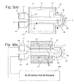
- Figure 3a illustrates a plan view of a single drop emitter unit 110 and a second plan view Figure 3b with the liquid chamber structure 33, enclosing the upper ink chamber 11 and including nozzle 30, removed.
- Upper ink chamber 11 has an arcuate portion 36 that generally surrounds the arcuate free end 28 of the thermo-mechanical actuator 15.
- thermo-mechanical actuator 15 shown in phantom in Figure 3a can be seen with solid lines in Figure 3b.
- the cantilevered element 20 of thermo-mechanical actuator 15 extends from edge 14 of lower ink chamber 12 that is formed in substrate 10.
- Cantilevered element portion 17 is bonded to substrate 10 and anchors the cantilever.
- the cantilevered element 20 of the actuator has the shape of a paddle, an extended flat shaft ending with a disc of larger diameter than the shaft width. This shape is merely illustrative of cantilever actuators that can be used. Many other shapes are applicable.
- the paddle shape aligns the nozzle 30 with the center of the cantilever free end 28.
- the lower liquid chamber 12 has a curved wall portion 16 that conforms to the arcuate shaped portion 34 of the actuator free end 28, spaced away to provide a clearance gap 13 for actuator movement.
- the arcuate portion 34 of free end 28 and the arcuate portions of the upper and lower liquid chambers 36 and 16, are illustrated to extend for an angular amount ⁇ , wherein ⁇ is 180 degrees or more.
- the opposing free edges 19 of the thermo-mechanical actuator, together with free end 28, define an outline of the moveable portion of the thermo-mechanical actuator.
- Figure 3b illustrates schematically the attachment of electrical pulse source 200 to the electrically resistive heater 27 at interconnect terminals 42 and 44. Voltage differences are applied to voltage terminals 42 and 44 to cause resistance heating via u-shaped resistor 27. This is generally indicated by an arrow showing a current I.
- the actuator free end moves toward the viewer when pulsed and drops are emitted toward the viewer from the nozzle 30 in liquid chamber structure 28. This geometry of actuation and drop emission is called a "roof shooter" in many ink jet disclosures.
- Figure 4 illustrates in side view a cantilevered element 20 according to a preferred embodiment of the present invention.
- the cantilevered element 20 is in a first position and in Figure 4b it is shown deflected upward to a second position.
- the cantilevered element is shown in a recoiled, downwardly deflected position.
- Cantilevered element 20 is anchored to substrate 10 that serves as a base element for the thermo-mechanical actuator.
- Cantilevered element 20 extends from wall edge 14 of substrate base element 10.
- Cantilevered element 20 is constructed of several layers.
- Layer 24 is the deflector layer that causes the upward deflection when it is thermally elongated with respect to other layers in the cantilevered element.
- the deflector material is chosen to have a high coefficient of thermal expansion. Further, in the illustrated configuration, the deflector material is electrically resistive and a portion is patterned into a heater resistor for receiving electrical pulses to heat the thermo-mechanical actuator. Electrically resistive materials are generally susceptible to chemical interaction with components or impurities in a working fluid.
- Top layer 26 is formed with a top material having a substantially lower coefficient of thermal expansion than the deflector material and has a layer thickness that is on the order of, or larger than, the deflector layer thickness. Top layer 26 in Figure 4 does not expand as much as the deflector layer when heated thereby constraining the deflector layer from simply elongating and causing the overall cantilevered element 20 to bend upward, away from deflector layer 24.
- the top layer material is a dielectric.
- the top layer material is also chosen to be chemically inert to the working fluid.
- Bottom layer 22 is formed of a bottom material that is chemically inert to the working fluid being used with the device, for example, an ink for ink jet printing. It protects the lower surface of the deflector material from chemical interaction.
- the bottom material serves as an etch stop during a manufacturing process step described hereinbelow in which substrate material is removed beneath the thermo-mechanical actuator.
- top and bottom are chosen to reference layers with respect to position relative to the substrate. These layers also play a role in determining which direction the deflector layer causes the thermo-mechanical actuator to bend. If both layers were formed of the same materials and of equal thickness, the actuator might not bend at all. The deflector layer will be caused to bend towards whichever layer, top or bottom, is more constraining as a result of its thickness, thermal expansion coefficient and Young's modulus. The biasing of the movement direction is readily achieved by making the layer that is toward the desired direction substantially thicker than the away layer.
- electrically resistive heating apparatus is adapted to apply heat pulses and electrical pulses with duration of less than 10 ⁇ secs and, preferably, with duration less than 4 ⁇ secs.
- the quiescent first position may be a partially bent condition of the cantilevered element 20 rather than the horizontal condition illustrated Figures 4a and 10c.
- the actuator may be bent upward or downward at room temperature because of internal stresses that remain after one or more microelectronic deposition or curing processes.
- the device may be operated at an elevated temperature for various purposes, including thermal management design and ink property control. If so, the first position may be substantially bent.
- the cantilevered element will be said to be quiescent or in its first position when the free end is not significantly changing in deflected position.
- the first position is depicted as horizontal in Figures 4a and 10c.
- operation of thermo-mechanical actuators about a bent first position are known and anticipated by the inventors of the present invention and are fully within the scope of the present inventions.
- Figures 5 through 10(c) illustrate methods of manufacturing applied to an ink jet device or other liquid drop emitter having a cantilevered element thermo-mechanical actuator, as illustrated in Figures 3 and 4.
- Figure 5 illustrates a perspective view of a single cantilevered element at an initial stage of a manufacturing process.
- Bottom layer 22 has been formed of a bottom material on substrate 10. The bottom material has been removed in a bottom layer pattern so that the substrate is now exposed in some areas. These exposed areas of the substrate will eventually be removed to form portions of the lower liquid chamber 12 and the clearance gap 13 illustrated in Figure 3b.
- the large rectangular areas of substrate exposure are refill areas 35, which are sized to provide adequate upper chamber refill flow during rapid liquid drop emission, thus allowing a tightly fitting clearance gap 13 to improve drop ejection efficiency without compromising refill.
- the moveable portion of the bottom layer 22 has opposing free edges 19.
- the substrate 10 is also exposed in free edge area 18 adjacent the arcuate edge 34 of the free end.
- the bottom material for the cantilevered element thermo-mechanical actuator is deposited as a thin layer so to minimize its impedance of the upward deflection of the finished actuator.
- a chemically inert, pinhole free material is preferred so as to provide chemical and electrical protection of the deflector material that will be formed on the bottom layer.
- a preferred method of the present inventions is to use silicon wafer as the substrate material and then a wet oxidation process to grow a thin layer of silicon dioxide.
- a high temperature chemical vapor deposition of a silicon oxide, nitride or carbon film may be used to form a thin, pinhole free dielectric layer with properties that are chemically inert to the working fluid.
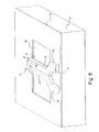
- Figure 6 illustrates the addition of a deflector layer 24 over the previously deposited bottom layer.
- Deflector material is removed in a deflector layer pattern.
- the deflector layer is comprised of an electrically resistive deflector material, a portion of which is patterned into a u-shaped heater resister 27 which can be addressed by input leads 42 and 44.
- Deflector material is removed so that it does not overlap the bottom layer material.
- the deflector material is removed well back from edges 19 of bottom layer 22.
- the deflector layer and the bottom layer could be patterned together using the bottom layer pattern so that both layers coincided at free edges 19. A subsequent patterning of the deflector layer only would then be needed to introduce any unique features such as the resistor and addressing leads.
- the deflector material is selected to have a high coefficient of thermal expansion, for example, a metal.
- the deflector material is electrically resistive and used to form a heater resistor.
- Nichrome (NiCr) is a well known material that could be used as a deflector material.
- a 60% copper, 40% nickel alloy, cupronickel, and titanium nitride are disclosed in K. Silverbrook U.S. Patents Nos. 6,254,793 and 6,274,056.
- TiAl intermetallic titanium aluminide
- TiAl material may be formed by RF or DC magnetron sputtering in argon gas. It has been found that desirable TiAl films are predominantly disordered face-centered cubic (fcc) in crystalline structure and have a stoichiometry of Al 4-x Ti x , where 0.6 ⁇ x ⁇ 1.4. Titanium aluminide may be pattern etched with a standard chlorine-based dry etching system commonly used in microelectronic device fabrication for aluminum etching.
- the resistivity of the deflector material is in an appropriate range, then a portion of the deflector layer can be patterned as a resistor and used to introduce heat pulses to the thermo-mechanical actuator. Alternatively, a separate electrical resistor layer can be added or heat energy can be coupled to the actuator by other means such as light energy or inductively coupled electrical energy.
- the titanium aluminide material preferred in the present inventions has a resistivity of ⁇ 160 ⁇ ohm-cm, which is a reasonable resistivity for a heater resistor that could be driven by integrated circuit transistors. Typical thicknesses, h d , for the deflector layer are 0.5 ⁇ m to 2 ⁇ m.
- Figure 7 illustrates in perspective view the addition of a top layer 26 formed over the deflector layer 24, bottom layer 22, and substrate 10.
- the top layer 26 is removed in a top layer pattern that generally leaves top layer material covering the deflector material in the moveable area of the cantilevered element.
- the top layer as illustrated in Figure 7 performs two main functions, it protects the deflector material from chemical interaction with the working fluid, and it biases the deflection of cantilevered element 20 towards itself.
- a typical dielectric material used for the top material is silicon dioxide or silicon nitride. Many other dielectrics may be used.
- oxides and nitrides deposited by low temperature CVD processes will provide substantial chemical interaction protection for the deflector layer.
- the top layer pattern leaves top material covering the free edges of the deflector layer so as to provide chemical and electrical passivation. Further, the top material free edges may underlap, overlap or be coincident with bottom layer free edges 19.
- An underlapping condition is illustrated in Figure 7. If the top material is allowed to overlap the bottom material into free edge area 18 on substrate 10, it cannot be allowed to completely cover free edge area 18.
- free edge area 18 adjacent the arcuate free edge 34 of the free end 28 of cantilevered element 20 must remain so that a subsequent process step of removing the substrate beneath free edge area 18 is effective in releasing the moveable portion of the cantilevered element 20 from attachment to the substrate.
- top layer 26 completes the construction of the cantilevered element 20 for the liquid drop emitter 110 being discussed.
- Other layers may be added for other purposes, for example a separate layer and insulator to form a resistive heater, instead of using the deflector material for this function.
- the top, deflector and bottom layers may be comprised of sub-layers or layers with graded material properties. Such additional layers and features are known and comprehended by the inventors as being within the scope of the methods of manufacture of the present inventions.
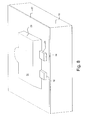
- Figure 8 shows the addition of a sacrificial layer 29 formed of a sacrificial material and removed in a sacrificial layer pattern.
- the sacrificial layer pattern leaves the sacrificial material formed into the shape of the interior of an upper liquid chamber 11 of a liquid drop emitter.
- this chamber space can be understood as a movement volume for the thermo-mechanical actuator.
- movement volume it is meant the space into which the moveable portion of the thermo-mechanical actuator can travel freely without being impeded by structural elements.
- the sacrificial material is intended as a temporary form whose outer surface shape will become the inner surface shape of the structure layer that is to be next added.
- the sacrificial material must be able to fully conform to the underlying layered structure of the cantilevered element including making good contact with the free edge area 18 on substrate 10.
- Figure 9 illustrates a patterned structure layer 33 formed by a structure material deposited over the sacrificial layer and other exposed layers on the substrate. Structure material is then removed according to a structure layer pattern resulting in the drop emitter liquid chamber 33 with walls, cover and nozzle 30, and arcuate wall portion 36 illustrated in Figure 9.
- the patterned structure layer 33 contains a movement volume 11 and provides a structure opening 30 that communicates with the sacrificial material still occupying the movement volume space. Electrical leads 42 and 44 are exposed for electrical attachment to an electrical pulse source.
- Suitable structure materials include plasma deposited silicon oxides or nitrides.
- the structure material must conform to the rather deep topography of the completed sacrificial layer 29.
- the sacrificial layer ranges in height above the substrate from ⁇ 1 ⁇ m in the area around electrical leads 42, 44 up to 5 ⁇ m - 15 ⁇ m at the upper surface 31 of the movement volume 11 (see Figure 8).
- the structure material must also be chemically inert to the working fluid and mechanically strong and durable enough to withstand drop ejection pressure pulses and some mechanical wiping for printhead maintenance purposes.
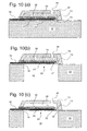
- Figures 10(a) - 10(c) show side views of the device through a section indicated as A-A in Figure 9.
- the sacrificial layer 29 is enclosed within the drop emitter chamber walls 33 except for nozzle opening 30.
- the substrate 10 is intact.
- the substrate is covered by sacrificial material in gap area 13 immediately above free edge area 18 adjacent the free edges of the cantilevered element.
- the most outer edge of the moveable portion of the cantilevered element aligns with the free edges 19 and 34 of bottom layer 22 as illustrated in Figures 5-7.
- substrate 10 is removed beneath the cantilevered element 20, the liquid chamber areas around and beside the cantilevered element 20 and the free edge area 18. This removal may be accomplished by an anisotropic etching process such as reactive ion etching for the case where the substrate used is single crystal silicon.
- anisotropic etching process such as reactive ion etching for the case where the substrate used is single crystal silicon.
- the sacrificial structure and liquid chamber steps are not needed and this step of etching,away substrate 10 may be used to release cantilevered element 20 from attachment to substrate 10.
- liquid entering from lower liquid chamber volume 12 may touch the bottom layer 22 of the cantilevered element 20, the sacrificial material in gap area 13, and the sacrificial material in the large refill areas 35 (see Figures 5-7) flanking the cantilevered element, not visible in this A-A cross sectional view lengthwise through the cantilevered element.
- the refill areas are sized to provide rapid refill of upper liquid chamber 11 following drop ejection for liquid drop emitter devices.
- the sacrificial material layer 29 has been removed using a penetrating process such as dry etching using oxygen and fluorine sources.
- the etchant gasses enter via the nozzle 30 and from the newly opened fluid supply chamber area 12, etched previously from the backside of substrate 10. This step removes the sacrificial material from the movement volume of the device, allowing the cantilevered element 20 to move freely and completes the fabrication of a liquid drop emitter structure.
- the process steps of removing the substrate material and removing the sacrificial material illustrated in Figure 10 may be performed in either order. It may be beneficial to remove the substrate material and then singulate individual devices leaving the sacrificial material intact to protect the movable portion of the thermo-mechanical actuator and prevent particles from entering the movement volume.
- a drop emitter device may be mechanically mounted, and interconnected electrically and fluidically with a protective filter, in a less clean environment if the sacrificial material is left inside the device until a later, final step in the overall manufacturing workflow.
- Figures 5 through 10c illustrate a preferred fabrication sequence. However, many other construction approaches may be followed using well known microelectronic fabrication processes and materials. For the purposes of the present invention, any fabrication approach which results in a cantilevered element including a deflector layer 24 and a top layer 26 may be followed. Further, in the illustrated sequence of Figures 5 through 10c, the liquid chamber 33 and nozzle 30 of a liquid drop emitter were formed in situ on substrate 10. Alternatively a thermo-mechanical actuator could be constructed separately and bonded to a liquid chamber component to form a liquid drop emitter.
- thermo-mechanically actuated liquid drop emitter may be varied by changing the parameters of the heat pulses applied to the actuator.
- the free end 28 is caused to move rapidly towards nozzle 30, accelerating a fluid volume generally having the area of the free end 28 times the amount of free end displacement, y(L).
- the volume of liquid emitted is roughly proportional to the amount of fluid displaced by the moving cantilevered element.
- the quantity (c ⁇ T) in Equation 1 is termed the thermal moment of the multi-layered structure.
- thermo-mechanical actuator The temperature of the thermo-mechanical actuator is raised by a heat pulse of energy E, applied at a power level P for a pulse time duration ⁇ p .
- E P ⁇ p .
- Equation 4 a first order equilibrium analysis of the relationship between the deflection of the free end 28 of the cantilevered element, which largely determines emitted drop volume, yields the following: From Equation 4, the emitted drop volume may be anticipated to increase proportionately to an increase in applied energy E. If a constant input power, P 0 , is utilized, then Equation 4 also implies that the drop volume will increase proportionately to an increase in pulse time duration ⁇ p .
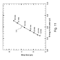
- the data plotted in Figure 11 were collected for a representative drop emitter filled with water and configured as illustrated in Figures 3 and 4.
- the cantilevered element 20 length L was 90 ⁇ m, the width of the rectangular portion of the cantilever and the diameter of the semi-circular free end 28 were both 30 ⁇ m.
- the nozzle 30 diameter was 14 ⁇ m.
- the resistance of a heater resistor 27 formed in a deflector layer 24 was 26 ohms. Individual data points are marked by dots along plot 250. Individual data points are also labeled with the drop velocity observed for each drop volume.
- liquid drop emitters for example ink jet printing, fire drops across a spacing gap distance, G p , to a predetermined receiver location, i.e. a pixel location in a raster image.
- the liquid drop emitter and the receiver are moved with respect to each other by a carriage mechanism at a relative velocity, v c , so that drops may be deposited at different locations in a time efficient fashion.
- a predictable drop velocity, v d0 is therefore necessary in order to direct drops to the intended location. If the drop velocity varies, then the flying time from the nozzle to the receiver plane, G p /v d0 , will vary.
- d c G p v c v d0 .
- Some amount of variation in d c i.e. some drop placement error relative to predetermined locations such as image pixel rasters, due to drop velocity variation, may be tolerable depending on the specific system application of the drop emitter. In ink jet printing such drop placement errors may affect the perceived sharpness of image edges or cause undesirable streaks or image density artifacts. A larger level of drop placement error may be tolerable for the printing of certain images, such as text and line graphics only, than is acceptable for printing an image having grayscale. Methods of operating a liquid drop emitter that emits drops at different velocities will be further discussed hereinbelow.
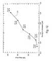
- Drop placement errors for drops having different volumes due to drop velocity variations, may be avoided by using methods of operating liquid drop emitters that achieve a substantially uniform drop velocity. It has been found by the inventors of the present inventions that the drop velocity of emitted drops having different volumes may be made substantially constant by adjusting both the time duration of the heat pulse, ⁇ p , and the applied power, P, to achieve different amounts of pulse energy input, E.
- Figure 12 shows experimental data 252 for drop volume emitted as a function of input energy applied using a pulse time duration ⁇ p and input power P adjusted to achieve a substantially constant drop velocity of 8 m/sec.
- the data plotted in Figure 12 were collected for a representative drop emitter filled with water and configured as illustrated in Figures 3 and 4.
- the drop emitter used was similar to that used for the data reported in Figure 11.
- the cantilevered element 20 length L was 90 ⁇ m; the width of the rectangular portion of the cantilever and the diameter of the semi-circular free end 28 both 30 ⁇ m; the nozzle 30 diameter was 14 ⁇ m; and the resistance of a heater resistor 27 formed in a deflector layer 24 was 26 ohms.
- Individual data points are marked by dots along plot 252. Individual data points are also labeled with the applied heat pulse duration ⁇ p in microseconds ( ⁇ s) and the applied power P in watts (W).
- Some preferred methods of operating a liquid drop emitter having a thermo-mechanical actuator according to the present inventions are to cause the emission of drops having substantially different volumes while having substantially the same velocity.
- the term "substantially different volumes”, when used herein, means that the range of drop volumes emitted is at least 20%, that is, that the largest drop emitted has at least 20% more volume than the smallest drop emitted.
- These preferred methods of operation are accomplished by selecting, for each drop volume to be emitted, appropriate heat pulse parameters including the total energy, power and pulse time duration. Higher values of the total input heat energy E are selected to emit larger drops. Lower values of the power P together with longer pulse time duration values ⁇ p are also selected to emit larger drops at substantially the same velocity.
- thermo-mechanical actuator configured as a cantilevered element having an arcuate free end that moves within a closely-spaced, surrounding, arcuate liquid chamber portion.
- This preferred configuration is generally illustrated by the plan views in Figures 3a and 3b. For such a configuration the movement of the free end 28 translates efficiently into moving the fluid behind the nozzle.
- Leakage of fluid around the free end 28 via the clearance distance 13 represents a loss of energy efficiency by weakening the direct proportionality between the amount of free end deflection and the volume of fluid that is moved toward the nozzle to form a jet.
- An arcuate shape minimizes the perimeter to area ratio of the free end, hence minimizes the length of the fluid leakage path around the free end. It has been found by the inventors of the present inventions that an arc of 180 degrees or more is preferable to minimize energy losses.
- Conforming the stationary arcuate portions of the upper and lower liquid chambers to the arcuate shape of the free end edge, and minimizing the clearance distance therebetween further reduces the leakage path. It has been found by the inventors of the present inventions that it is preferable to form as small a clearance distance as is reliably possible and preferably less than 3 microns.
- a cantilevered element thermo-mechanical actuator will exhibit a damped resonant oscillation following an initial thermal excitation pulse.
- cantilevered element 20 will quickly relax from the bent position illustrated in Figure 4b as elements 24 and 26 equilibrate in temperature, as heat is transferred to the working fluid and substrate 10, and due to mechanical restoring forces set up in elements 24 and 26.
- the relaxing cantilevered element 20 will over shoot the quiescent state, Figure 4a, and bend downwards as illustrated in Figure 4c.
- Cantilevered element 20 will continue to "ring" in a resonant oscillatory motion until damping mechanisms, such as internal friction and working fluid resistance, deplete and convert all residual mechanical energy to heat.
- the damped resonant oscillation effects described above must be considered in designing the operating method. Directing drop emissions at arbitrary times during the resonant oscillations may cause intended drop volumes and intended drop velocities to vary unacceptably.
- the present inventive methods of operating a liquid drop emitter preferably are carried out so as to avoid complications arising from intrinsic damped resonant oscillations of the cantilevered element. This is accomplished by selecting all pulse time duration values to be less than one-quarter cycle of the period of the fundamental resonant mode, ⁇ R .
- Figures 13 and 14 illustrate damped resonant oscillation of the free end 28 of a cantilever element 20 moving in fundamental mode.
- Figure 13 discloses experimental data for several parameter variations of the general thermo-mechanical actuator configuration illustrated in Figures 3a - 4c.
- the table in Figure 13 discloses the observed fundamental resonant frequency, F, the period of the fundamental resonance, ⁇ R , and the damping time constant, ⁇ D , for several different configurations of the cantilevered element length, L, width, W, and free end diameter, D.
- the damped resonant behavior disclosed was measured with water as the working fluid.
- ⁇ R is the period of the fundamental resonant oscillation mode
- ⁇ D is the time constant of damping factors.
- the maximum magnitude of displacement is normalized to 1.0.
- the time axis in Figure 14 is divided in units of ⁇ R .
- Curve 226 shows the exponential damping portion of Equation 6 for the case of curve 224.
- Curve 228 illustrates the electrical pulse that activated the thermo-mechanical activators initially.
- Activation pulse duration, ⁇ P should be less than one-quarter the resonant period, i.e. ⁇ P ⁇ 1/4 ⁇ R , to avoid the situation of contention between the natural spring recoil of the cantilevered element and the thermo-mechanical force introduced by the input heat energy pulse.
- the geometrical parameters for cantilevered elements given in the table of Figure 13 are typical of liquid emitter devices that are appropriate for high quality ink jet printing and other liquid drop emitter applications utilizing drop volumes of approximately 10 pL or less.
- the highest resonant frequency of these experimental devices was found to be 74 kHz, having a period of 13.5 ⁇ sec. Consequently, it is preferred to operate such a liquid drop emitter according to the present inventions by insuring that all input heat pulses have a time duration of approximately 3 ⁇ sec or less.
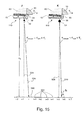
- Figure 15 illustrates the drop placement error that may be associated with varying drop velocity.
- a cut-away portion of a thermo-mechanically actuated drop emitter 110 is shown in side view in two positions indicated as “J" and "K". The cut-away portion of drop emitter 110 is drawn after Figure 4b showing the moment of drop emission.
- a first drop 52 having a first volume V 1d and an emission velocity v 1d0 is emitted.
- a second drop 54 having a second volume V 2d and a second emission velocity v 2d0 is emitted.
- first drop 52 is selected as a small volume drop and travels at a slow velocity.
- Second drop 54 is selected as a substantially larger volume drop, V 2d > V 1d , and travels at a substantially faster velocity, V 2d0 > v 1do .
- First and second drops 52 and 54 are intended to land at certain predetermined locations 502 on receiver or print plane 500.
- predetermined locations 502 are labeled (i-2), (i-1), (i), entirely,(i+7), and indicated by small plus signs.
- predetermined locations 502 are individual pixel raster positions along a single scan line.
- first drop 52 is intended to land on predetermined location (i)
- second drop 54 is intended to land on predetermined location (i+6).
- the receiver or print plane 500 is located a firing distance G P from the nozzle plane of drop emitter 110. Drop emitter 110 is illustrated moving at a velocity v c in a direction parallel to print plane 500, for example by means of a printhead carriage.
- First drop 52 is emitted when the nozzle of drop emitter 110 is opposite a print plane location just past predetermined location (i-1).
- Second drop 54 is emitted when the nozzle of drop emitter 110 is similarly opposite a print plane location just past predetermined location (i+5).
- the emission of first drop 52 is timed to occur just after passing predetermined location (i-1) so that it will land on predetermined print plane location (i).
- the emission of second drop 54 is similarly timed to occur just after passing predetermined location (i+5) and is intended to, but does not, fall on predetermined location (i+6), because it is traveling too fast.
- Second drop 54 lands at a point on the receiver 500 in between predetermined locations (i+5) and (i+6), an error distance ⁇ 2 away from predetermined location (i+6).
- Error distance ⁇ 2 adversely affects the quality of performance of the liquid drop emitter in a fashion depending on the specific application. For example, in the case of an ink jet printing application, misplacement of some of the print drops by a distance ⁇ 2 away from the intended pixel raster positions may cause perceptible anomalies, defects, in the image. For a microdosiometer application, the drop may fall outside of an intended chemical analysis site, leading to a false chemical measurement.
- Some preferred embodiments of the present inventions include methods of operating a liquid drop emitter to emit drops having substantially different drop volumes and substantially different velocities wherein the range of permitted velocities is predetermined to bound the drop velocity related drop placement errors.
- the range of permitted velocities may be different for different applications or application modes. For example, in ink jet printing, different image quality levels may allow different levels of drop placement error, hence a different permitted range of drop velocities.
- v d max and v d min be the maximum and minimum predetermined, permitted, drop velocities to bound the variation of drop placement at the print plane below a predetermined maximum error amount, ⁇ max .
- the following relationship governs the permitted drop velocities: It is common that the minimum velocity permitted, v d min , is selected in recognition of other drop misplacement error sources, especially off-axis tugging on the liquid jet arising from wetting anomalies and debris at the nozzle exit. For example, it may be the case that these nozzle front face effects are of such magnitude that a minimum drop velocity of 3 - 5 m/sec is necessary to bound drop placement errors from these sources.
- the maximum permitted velocity, v d max may then be selected to satisfy above Equation 7.
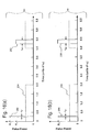
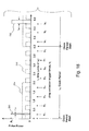
- Figures 16a and 16b illustrate input heat pulse parameters that might be used to generate first and second drops as illustrated in Figure 15.
- clock signal 264 is preferably synchronized to the movement of the printhead relative to predetermined pixel locations, rasters, at the print plane by some spatial encoding means.
- the drop firing pulses are initiated at a time ⁇ 1 ⁇ 4 ⁇ R following the low-to-high transition of clock signal 264.
- the low-to-high clock signal transition of clock signal 264 is a clock period start which may be used to time-reference events within a clock period.
- the first and second drops will follow trajectories that take them to predetermined pixel locations at the print plane.
- pulse time duration parameters are adjusted to provide the energy levels to generate large and small drops, E 2 > E 1 .
- P 0 is used, causing large drop 54 to be emitted at a higher velocity than small drop 52, v 2 > v 1 . Consequently, large drop 54 will arrive more quickly at the print plane and will be misplaced by a placement error distance as illustrated in Figure 15.
- Alternate preferred methods of operating liquid drop emitters to emit drops of substantially different volumes at substantially different velocities may be carried out by adjusting the time of application of activating heat pulses within a clock signal period. That is, in order to compensate for the quicker travel time to the print plane of faster drops, the heat pulse application may be delayed relative to that of a slower drop. Especially for high quality ink jet printing applications, it is important that each print drop arrive at a predetermined location on the print plane.
- a clock signal synchronized to the printhead-receiver motion, may be used to manage the timing of applied heat pulses, introducing an appropriate amount of time delay to synchronize the arrival of different velocity drops at the intended predetermined locations on the receiver.
- An appropriate amount of time delay may be introduced to synchronize the arrival of drops at predetermined locations on the receiver by associating a time delay factor, t d , with other heat pulse parameters, power and pulse time duration, used to generate a selected drop volume.
- a time delay factor t d
- a time delay quantity is associated with each pulse time duration. Longer heat pulse durations will generate larger and faster drops and have larger associated time delay factors.
- FIG. 17 A preferred method of operation utilizing time delay factors is illustrated in Figure 17.
- the method disclosed in Figure 17 is similar to the method illustrated by Figure 16b except that a unique time delay factor is associated with each applied heat pulse.
- Heat pulse 270 in Figure 17 generates a small first drop 52.
- Heat pulse 270 is initiated after a delay time, t 1 ⁇ .25 ⁇ R , following a low-to-high transition, the clock period start, of clock signal 264.
- Time delay t 1 is selected so that first small drop 52 will arrive at a first intended raster position on the receiver.
- Heat pulse 272 in Figure 17 generates a large second drop 54 that will be traveling at a substantially higher velocity than first small drop 52, as has been previously discussed. Heat pulse 272 is initiated after a larger time delay, t 2 ⁇ 1.15 ⁇ R , following a next clock period start. The larger time delay, t 2 , is calculated to compensate for the shorter transit time from drop emitter to receiver of second large drop 54 relative to first small drop 52. Large second drop 54 will arrive at a second raster position, adjacent to the first in the example of Figure 17. The second drop placement error that will occur in the example method of operating of Figure 16b is removed by the use of the larger time delay t 2 in the method according to Figure 17.
- FIG. 18 An alternate preferred method of providing time delay compensation to synchronize the arrival of drops having different velocities at predetermined locations in the print plane is illustrated by Figure 18.
- a clock signal 294 is divided into a number of sub-clocks 296 that provide a number of drop emission trigger edges within each clock period.
- sub-clock signal 296 provides eight high-to-low transitions per clock period, which may be used as eight trigger times, tr 1 to tr 8 .
- the subordinate trigger edges are sometimes referred to as "phases" of the clock signal. While illustrated as equally spaced in Figure 18, some number of trigger edges may be provided at non-equal time spacings within the clock period.
- each drop volume that is to be emitted is associated with one of the available trigger edges.
- first drop heat pulse 290 is associated with trigger edge tr 1
- second drop heat pulse 292 is associated with trigger edge tr 3 .
- the total clock period, ⁇ c is divided into eight equal parts by sub-clock 296 and the trigger edges are chosen to be the high-to-low transitions rather than a low-to-high edge as is used for the clock period start.
- Each drop volume choice is associated with the trigger edge that will result in the least drop placement error due to each drop velocity.
- the methods of Figure 18 may also be implemented by generating a finite set of sub-clock trigger edges to accompany a finite set of emitted drop volumes.
- a system might be configured to emit three discrete drop volumes, each drop size having an associated specific velocity and optimum delay time.
- a sub-clock is then constructed to provide three trigger edges that occur at the optimum delay times.
- Such a system would operate as if the signal clock had three phases, one for each drop size.
- Image data which directs that a given pixel location should be printed with one of the three drops sizes, or none, could then be organized into three binary drop command files, drop or no drop, one for each of the three phases, and executed in time-interleaved fashion.
- a potential advantage of the preferred methods of the present inventions, which utilize drops having different velocities, is that a variable drop volume system may be constructed and operated using a constant power input source and other parameters managed via various timing means. Such an approach may offer lower cost and higher reliability hardware as compared to an approach in which the input power must be finely adjusted on a drop-by-drop basis to equalize drop velocities.
- thermo-mechanical actuators having a laminated construction comprised of a deflector layer and a top layer that is, a bi-layer device.
- the inventors of the present inventions contemplate that any construction configuration of a thermo-mechanical actuator that is useful in a liquid drop emitter may be used in practicing the inventions.
- thermo-mechanical actuators having multiple deflector layers may be operated according to the methods of the present inventions, in a fashion similar to the single deflector layer constructions described in detail herein.
- thermo-mechanical actuator devices While much of the foregoing description was directed to the configuration and operation of a single thermo-mechanical actuator or liquid drop emitter, it should be understood that the present invention is applicable to forming arrays and assemblies of multiple drop emitter units. Also it should be understood that thermo-mechanical actuator devices according to the present invention may be fabricated concurrently with other electronic components and circuits, or formed on the same substrate before or after the fabrication of electronic components and circuits.
Landscapes
- Engineering & Computer Science (AREA)
- Manufacturing & Machinery (AREA)
- Particle Formation And Scattering Control In Inkjet Printers (AREA)
- Ink Jet (AREA)
Abstract
Description
The top layer pattern leaves top material covering the free edges of the deflector layer so as to provide chemical and electrical passivation. Further, the top material free edges may underlap, overlap or be coincident with bottom layer free edges 19. An underlapping condition is illustrated in Figure 7. If the top material is allowed to overlap the bottom material into free edge area 18 on substrate 10, it cannot be allowed to completely cover free edge area 18. Some portion of free edge area 18 adjacent the arcuate free edge 34 of the free end 28 of cantilevered element 20 must remain so that a subsequent process step of removing the substrate beneath free edge area 18 is effective in releasing the moveable portion of the cantilevered element 20 from attachment to the substrate.



Claims (7)
- A method for operating a liquid drop emitter for emitting liquid drops of substantially different volumes having substantially a same target velocity v0, said liquid drop emitter comprising a chamber, filled with a liquid, having a nozzle for emitting drops of the liquid, a thermo-mechanical actuator having a moveable portion within the chamber for applying pressure to the liquid at the nozzle, and apparatus adapted to apply heat pulses to the thermo-mechanical actuator, the method for operating comprising:(a) applying a first heat pulse having a first power P1, first pulse duration τp1, and first energy E1 = P1 × τp1, displacing the movable portion of the actuator so that a drop is emitted having a first drop volume Vd1 and traveling substantially at the target velocity v0 ; and(b) applying a second heat pulse having a second power P2, second pulse duration τp2, and second energy E2 = P2 × τp2, displacing the movable portion of the actuator so that a drop is emitted having a second drop volume Vd2 and traveling substantially at the target velocity v0, wherein Vd2 > Vd1, E2 > E1, τp2 > τp1 and P2 < P1.
- A method for operating a liquid drop emitter for emitting liquid drops of substantially different volumes having a drop velocity that is within a predetermined drop velocity range, vd min to vd max, said liquid drop emitter comprising a chamber, filled with a liquid, having a nozzle for emitting drops of the liquid, a thermo-mechanical actuator having a moveable portion within the chamber for applying pressure to the liquid at the nozzle, and apparatus adapted to apply heat pulses to the thermo-mechanical actuator, the method for operating comprising:(a) selecting a maximum drop velocity range, vd min to vd max;(a) applying a first heat pulse having a first power P1, first pulse duration τp1, and first energy E1 = P1 × τp1, displacing the movable portion of the actuator so that a drop is emitted having a first drop volume Vd1 and traveling at a first velocity, v1d, wherein vd min ≤ v1d < vd max; and(c) applying a second heat pulse having a second power P2, second pulse duration τp2, and second energy E2 = P2 × τp2, displacing the movable portion of the actuator so that a drop is emitted having a second drop volume Vd2 and traveling at a second velocity, v2d wherein v1d < v2d ≤ vd max, and wherein Vd2 is substantially greater than Vd1, E2 > E1, and τp2 > τp1.
- The method of claim 1 or 2 wherein the liquid drop emitter is a drop-on-demand ink jet printhead and the liquid is an ink for printing image data.
- The method of claim 1 or 2 wherein the thermo-mechanical actuator is configured as a cantilever extending from a wall of the chamber and having a free end adjacent the nozzle and moveable within the chamber.
- The method of claim 1 or 2 wherein the thermo-mechanical actuator includes a deflector layer constructed of a deflector material having a high coefficient of thermal expansion and a top layer, attached to the deflector layer, constructed of a top material having a low coefficient of thermal expansion.
- The method of claim 2 wherein P2 = P1.
- A liquid drop emitter for emitting liquid drops of substantially different volumes having a drop velocity that is within a predetermined drop velocity range, vd min to vd max, said liquid drop emitter comprising:(a) a chamber (11; 12), formed in a substrate (10), filled with a liquid and having a nozzle (30) for emitting drops of the liquid and having an arcuate chamber portion (16);(b) a thermo-mechanical actuator (15) having a cantilevered element (20) extending a from a wall (14) of the chamber and having a free end (28) with a tip perimeter having an arcuate shape, the tip perimeter spaced away from the arcuate chamber portion by a clearance distance and moveable within the arcuate chamber portion for applying pressure to the liquid at the nozzle;(c) apparatus (42; 44; 200) adapted to apply heat pulses to the thermo-mechanical actuator, wherein drops having substantially different volumes are emitted at one of a drop velocities within a range vd min to vd max and substantially a target velocity v0.
Applications Claiming Priority (2)
| Application Number | Priority Date | Filing Date | Title |
|---|---|---|---|
| US329566 | 2001-10-15 | ||
| US10/329,566 US6896346B2 (en) | 2002-12-26 | 2002-12-26 | Thermo-mechanical actuator drop-on-demand apparatus and method with multiple drop volumes |
Publications (3)
| Publication Number | Publication Date |
|---|---|
| EP1433610A2 true EP1433610A2 (en) | 2004-06-30 |
| EP1433610A3 EP1433610A3 (en) | 2004-08-25 |
| EP1433610B1 EP1433610B1 (en) | 2010-02-10 |
Family
ID=32469034
Family Applications (1)
| Application Number | Title | Priority Date | Filing Date |
|---|---|---|---|
| EP03079078A Expired - Lifetime EP1433610B1 (en) | 2002-12-26 | 2003-12-15 | Thermo-mechanical actuator drop-on-demand apparatus and method with multiple drop volumes |
Country Status (4)
| Country | Link |
|---|---|
| US (1) | US6896346B2 (en) |
| EP (1) | EP1433610B1 (en) |
| JP (1) | JP4355204B2 (en) |
| DE (1) | DE60331215D1 (en) |
Cited By (3)
| Publication number | Priority date | Publication date | Assignee | Title |
|---|---|---|---|---|
| EP1634708A3 (en) * | 2004-09-08 | 2009-01-14 | Sony Corporation | Liquid ejection head and liquid ejection apparatus |
| EP2039516A1 (en) * | 2007-09-18 | 2009-03-25 | Konica Minolta Holdings, Inc. | Liquid droplet ejecting apparatus and liquid droplet ejecting method |
| CN114083903A (en) * | 2021-12-23 | 2022-02-25 | 东莞市图创智能制造有限公司 | Printing apparatus for testing liquid performance and control method thereof |
Families Citing this family (38)
| Publication number | Priority date | Publication date | Assignee | Title |
|---|---|---|---|---|
| US7281778B2 (en) | 2004-03-15 | 2007-10-16 | Fujifilm Dimatix, Inc. | High frequency droplet ejection device and method |
| US8491076B2 (en) | 2004-03-15 | 2013-07-23 | Fujifilm Dimatix, Inc. | Fluid droplet ejection devices and methods |
| US8128753B2 (en) | 2004-11-19 | 2012-03-06 | Massachusetts Institute Of Technology | Method and apparatus for depositing LED organic film |
| US8986780B2 (en) | 2004-11-19 | 2015-03-24 | Massachusetts Institute Of Technology | Method and apparatus for depositing LED organic film |
| EP1836056B1 (en) | 2004-12-30 | 2018-11-07 | Fujifilm Dimatix, Inc. | Ink jet printing |
| CN101287605B (en) * | 2005-10-10 | 2012-04-25 | 西尔弗布鲁克研究有限公司 | Low-consumption electrode connection for ink-jet printhead |
| US7753496B2 (en) | 2005-10-11 | 2010-07-13 | Silverbrook Research Pty Ltd | Inkjet printhead with multiple chambers and multiple nozzles for each drive circuit |
| US7401890B2 (en) | 2005-10-11 | 2008-07-22 | Silverbrook Research Pty Ltd | Intercolour surface barriers in multi colour inkjet printhead |
| US7465032B2 (en) | 2005-10-11 | 2008-12-16 | Silverbrook Research Pty Ltd. | Printhead with inlet filter for ink chamber |
| US7712884B2 (en) | 2005-10-11 | 2010-05-11 | Silverbrook Research Pty Ltd | High density thermal ink jet printhead |
| US7445317B2 (en) | 2005-10-11 | 2008-11-04 | Silverbrook Research Pty Ltd | Inkjet printhead with droplet stem anchor |
| US7470010B2 (en) | 2005-10-11 | 2008-12-30 | Silverbrook Research Pty Ltd | Inkjet printhead with multiple ink inlet flow paths |
| US7322681B2 (en) | 2005-10-11 | 2008-01-29 | Silverbrook Research Pty Ltd | Printhead with ink feed to chamber via adjacent chamber |
| US7661800B2 (en) | 2005-10-11 | 2010-02-16 | Silverbrook Research Pty Ltd | Inkjet printhead with multiple heater elements and cross bracing |
| US7744195B2 (en) | 2005-10-11 | 2010-06-29 | Silverbrook Research Pty Ltd | Low loss electrode connection for inkjet printhead |
| US7988247B2 (en) | 2007-01-11 | 2011-08-02 | Fujifilm Dimatix, Inc. | Ejection of drops having variable drop size from an ink jet printer |
| CN101754859B (en) * | 2007-06-14 | 2012-05-30 | 麻省理工学院 | Method and apparatus for depositing films |
| US8556389B2 (en) | 2011-02-04 | 2013-10-15 | Kateeva, Inc. | Low-profile MEMS thermal printhead die having backside electrical connections |
| US11975546B2 (en) | 2008-06-13 | 2024-05-07 | Kateeva, Inc. | Gas enclosure assembly and system |
| US9604245B2 (en) | 2008-06-13 | 2017-03-28 | Kateeva, Inc. | Gas enclosure systems and methods utilizing an auxiliary enclosure |
| US12018857B2 (en) | 2008-06-13 | 2024-06-25 | Kateeva, Inc. | Gas enclosure assembly and system |
| US12064979B2 (en) | 2008-06-13 | 2024-08-20 | Kateeva, Inc. | Low-particle gas enclosure systems and methods |
| US8899171B2 (en) | 2008-06-13 | 2014-12-02 | Kateeva, Inc. | Gas enclosure assembly and system |
| US10434804B2 (en) | 2008-06-13 | 2019-10-08 | Kateeva, Inc. | Low particle gas enclosure systems and methods |
| US9048344B2 (en) | 2008-06-13 | 2015-06-02 | Kateeva, Inc. | Gas enclosure assembly and system |
| US8383202B2 (en) | 2008-06-13 | 2013-02-26 | Kateeva, Inc. | Method and apparatus for load-locked printing |
| US7997690B2 (en) * | 2008-09-29 | 2011-08-16 | Silverbrook Research Pty Ltd | Inkjet printer |
| US20100188457A1 (en) * | 2009-01-05 | 2010-07-29 | Madigan Connor F | Method and apparatus for controlling the temperature of an electrically-heated discharge nozzle |
| EP2425470A2 (en) | 2009-05-01 | 2012-03-07 | Kateeva, Inc. | Method and apparatus for organic vapor printing |
| US8393702B2 (en) * | 2009-12-10 | 2013-03-12 | Fujifilm Corporation | Separation of drive pulses for fluid ejector |
| US8797373B2 (en) | 2010-03-18 | 2014-08-05 | Ricoh Company, Ltd. | Liquid droplet ejecting method, liquid droplet ejection apparatus, inkjet recording apparatus, production method of fine particles, fine particle production apparatus, and toner |
| WO2012138366A1 (en) | 2011-04-08 | 2012-10-11 | Kateeva, Inc. | Method and apparatus for printing using a facetted drum |
| CN103182844B (en) * | 2011-12-27 | 2015-06-03 | 珠海纳思达企业管理有限公司 | Liquid spray head |
| JP2013248762A (en) * | 2012-05-30 | 2013-12-12 | Toshiba Corp | Inkjet recording head |
| FR2996163B1 (en) * | 2012-10-03 | 2016-02-05 | Essilor Int | METHOD OF PRINTING A PATTERN BY INKJET ON A SURFACE |
| WO2015100375A1 (en) | 2013-12-26 | 2015-07-02 | Kateeva, Inc. | Thermal treatment of electronic devices |
| WO2015112454A1 (en) | 2014-01-21 | 2015-07-30 | Kateeva, Inc. | Apparatus and techniques for electronic device encapsulation |
| KR102850075B1 (en) | 2014-04-30 | 2025-08-25 | 카티바, 인크. | Gas cushion apparatus and techniques for substrate coating |
Family Cites Families (30)
| Publication number | Priority date | Publication date | Assignee | Title |
|---|---|---|---|---|
| US3946398A (en) * | 1970-06-29 | 1976-03-23 | Silonics, Inc. | Method and apparatus for recording with writing fluids and drop projection means therefor |
| SE349676B (en) * | 1971-01-11 | 1972-10-02 | N Stemme | |
| US4296421A (en) * | 1978-10-26 | 1981-10-20 | Canon Kabushiki Kaisha | Ink jet recording device using thermal propulsion and mechanical pressure changes |
| JPS59143654A (en) * | 1983-02-05 | 1984-08-17 | Konishiroku Photo Ind Co Ltd | Liquid discharge apparatus |
| US4513299A (en) * | 1983-12-16 | 1985-04-23 | International Business Machines Corporation | Spot size modulation using multiple pulse resonance drop ejection |
| US5202659A (en) * | 1984-04-16 | 1993-04-13 | Dataproducts, Corporation | Method and apparatus for selective multi-resonant operation of an ink jet controlling dot size |
| JPH0230543A (en) | 1988-07-21 | 1990-01-31 | Seiko Epson Corp | Ink jet head |
| DE69015953T2 (en) * | 1989-10-10 | 1995-05-11 | Xaar Ltd | Printing process with several tonal values. |
| US5726690A (en) * | 1991-05-01 | 1998-03-10 | Hewlett-Packard Company | Control of ink drop volume in thermal inkjet printheads by varying the pulse width of the firing pulses |
| US5689291A (en) * | 1993-07-30 | 1997-11-18 | Tektronix, Inc. | Method and apparatus for producing dot size modulated ink jet printing |
| US5801732A (en) * | 1994-09-23 | 1998-09-01 | Dataproducts Corporation | Piezo impulse ink jet pulse delay to reduce mechanical and fluidic cross-talk |
| JPH08118641A (en) * | 1994-10-20 | 1996-05-14 | Canon Inc | Inkjet head, inkjet head cartridge, inkjet device, and ink container for inkjet head cartridge in which ink is re-injected |
| US5599695A (en) * | 1995-02-27 | 1997-02-04 | Affymetrix, Inc. | Printing molecular library arrays using deprotection agents solely in the vapor phase |
| JP3257340B2 (en) * | 1995-05-24 | 2002-02-18 | 松下電器産業株式会社 | Liquid coating method, liquid coating apparatus and slit nozzle |
| SE9503141D0 (en) * | 1995-09-12 | 1995-09-12 | Siemens Elema Ab | Anesthesia apparatus |
| JP3491187B2 (en) * | 1996-02-05 | 2004-01-26 | セイコーエプソン株式会社 | Recording method using ink jet recording apparatus |
| JPH09300613A (en) * | 1996-03-15 | 1997-11-25 | Hitachi Koki Co Ltd | Driving method of on-demand type multi-nozzle inkjet head |
| US5997124A (en) * | 1997-03-12 | 1999-12-07 | Raster Graphics Inc. | Method and apparatus for drop volume normalization in an ink jet printing operation |
| US6095630A (en) * | 1997-07-02 | 2000-08-01 | Sony Corporation | Ink-jet printer and drive method of recording head for ink-jet printer |
| US6239821B1 (en) * | 1997-07-15 | 2001-05-29 | Silverbrook Research Pty Ltd | Direct firing thermal bend actuator ink jet printing mechanism |
| AUPO807497A0 (en) * | 1997-07-15 | 1997-08-07 | Silverbrook Research Pty Ltd | A method of manufacture of an image creation apparatus (IJM23) |
| US6234609B1 (en) * | 1997-07-15 | 2001-05-22 | Silverbrook Research Pty Ltd | High Young's modulus thermoelastic ink jet printing mechanism |
| AUPO794797A0 (en) * | 1997-07-15 | 1997-08-07 | Silverbrook Research Pty Ltd | A device (MEMS07) |
| AUPO803597A0 (en) * | 1997-07-15 | 1997-08-07 | Silverbrook Research Pty Ltd | Image creation method and apparatus (IJ06) |
| US6254793B1 (en) * | 1997-07-15 | 2001-07-03 | Silverbrook Research Pty Ltd | Method of manufacture of high Young's modulus thermoelastic inkjet printer |
| AUPP653998A0 (en) * | 1998-10-16 | 1998-11-05 | Silverbrook Research Pty Ltd | Micromechanical device and method (ij46B) |
| AUPP993099A0 (en) * | 1999-04-22 | 1999-05-20 | Silverbrook Research Pty Ltd | A micromechancial device and method(ij46p2b) |
| US6318847B1 (en) * | 2000-03-31 | 2001-11-20 | Hewlett-Packard Company | Segmented heater resistor for producing a variable ink drop volume in an inkjet drop generator |
| DE60132595T2 (en) | 2000-08-11 | 2008-06-19 | Dimatix, Inc. | INK-JET PRINTING |
| US6435666B1 (en) * | 2001-10-12 | 2002-08-20 | Eastman Kodak Company | Thermal actuator drop-on-demand apparatus and method with reduced energy |
-
2002
- 2002-12-26 US US10/329,566 patent/US6896346B2/en not_active Expired - Fee Related
-
2003
- 2003-12-15 DE DE60331215T patent/DE60331215D1/en not_active Expired - Lifetime
- 2003-12-15 EP EP03079078A patent/EP1433610B1/en not_active Expired - Lifetime
- 2003-12-26 JP JP2003433687A patent/JP4355204B2/en not_active Expired - Fee Related
Cited By (5)
| Publication number | Priority date | Publication date | Assignee | Title |
|---|---|---|---|---|
| EP1634708A3 (en) * | 2004-09-08 | 2009-01-14 | Sony Corporation | Liquid ejection head and liquid ejection apparatus |
| EP2039516A1 (en) * | 2007-09-18 | 2009-03-25 | Konica Minolta Holdings, Inc. | Liquid droplet ejecting apparatus and liquid droplet ejecting method |
| US7950760B2 (en) | 2007-09-18 | 2011-05-31 | Konica Minolta Holdings, Inc. | Liquid droplet ejecting apparatus and liquid droplet ejecting method |
| CN114083903A (en) * | 2021-12-23 | 2022-02-25 | 东莞市图创智能制造有限公司 | Printing apparatus for testing liquid performance and control method thereof |
| CN114083903B (en) * | 2021-12-23 | 2024-02-02 | 东莞市图创智能制造有限公司 | Printing apparatus for testing liquid properties and control method thereof |
Also Published As
| Publication number | Publication date |
|---|---|
| US6896346B2 (en) | 2005-05-24 |
| DE60331215D1 (en) | 2010-03-25 |
| JP4355204B2 (en) | 2009-10-28 |
| US20040146055A1 (en) | 2004-07-29 |
| EP1433610A3 (en) | 2004-08-25 |
| JP2004209981A (en) | 2004-07-29 |
| EP1433610B1 (en) | 2010-02-10 |
Similar Documents
| Publication | Publication Date | Title |
|---|---|---|
| EP1433610B1 (en) | Thermo-mechanical actuator drop-on-demand apparatus and method with multiple drop volumes | |
| EP1302319B1 (en) | Thermal actuator drop-on-demand apparatus and method with reduced energy | |
| EP1364792B1 (en) | Multi-layer thermal actuator with optimized heater length and method of operating same | |
| EP1329319B1 (en) | Thermal actuator with optimized heater length | |
| US6644786B1 (en) | Method of manufacturing a thermally actuated liquid control device | |
| JP4758600B2 (en) | Double-acting thermal actuator and operating method thereof | |
| JP5567347B2 (en) | Variable-size droplet ejection from inkjet printers | |
| EP1334832B1 (en) | Tri-layer thermal actuator and method of operating | |
| EP1308282B1 (en) | Thermal actuator drop-on-demand apparatus and method for high frequency | |
| EP1419885A2 (en) | Thermal actuator with spatial thermal pattern | |
| JP2593940B2 (en) | Driving method of inkjet recording head | |
| JP2010506749A (en) | Continuous droplet emitter with reduced stimulation crosstalk | |
| US6705716B2 (en) | Thermal ink jet printer for printing an image on a receiver and method of assembling the printer | |
| JP2004082733A (en) | Tapered thermal actuator | |
| US7029085B2 (en) | Ink jet head and ink jet printer | |
| US6250740B1 (en) | Pagewidth image forming system and method | |
| US6848771B2 (en) | Method of operating a thermal actuator and liquid drop emitter with multiple pulses | |
| JP2000043269A (en) | Liquid jet recording head and method | |
| JP2003136729A (en) | Liquid jet recording head and method | |
| JPH05330047A (en) | Substrate for ink-jet recording head, ink-jet recording head and ink-jet recording device | |
| JP2003136730A (en) | Liquid jet recording head and method | |
| JP2003063011A (en) | Inkjet head | |
| JP2004001342A (en) | Inkjet head resistance adjustment method |
Legal Events
| Date | Code | Title | Description |
|---|---|---|---|
| PUAI | Public reference made under article 153(3) epc to a published international application that has entered the european phase |
Free format text: ORIGINAL CODE: 0009012 |
|
| AK | Designated contracting states |
Kind code of ref document: A2 Designated state(s): AT BE BG CH CY CZ DE DK EE ES FI FR GB GR HU IE IT LI LU MC NL PT RO SE SI SK TR |
|
| AX | Request for extension of the european patent |
Extension state: AL LT LV MK |
|
| PUAL | Search report despatched |
Free format text: ORIGINAL CODE: 0009013 |
|
| AK | Designated contracting states |
Kind code of ref document: A3 Designated state(s): AT BE BG CH CY CZ DE DK EE ES FI FR GB GR HU IE IT LI LU MC NL PT RO SE SI SK TR |
|
| AX | Request for extension of the european patent |
Extension state: AL LT LV MK |
|
| 17P | Request for examination filed |
Effective date: 20050131 |
|
| AKX | Designation fees paid |
Designated state(s): DE FR GB |
|
| RBV | Designated contracting states (corrected) |
Designated state(s): DE FR GB |
|
| 17Q | First examination report despatched |
Effective date: 20070321 |
|
| GRAP | Despatch of communication of intention to grant a patent |
Free format text: ORIGINAL CODE: EPIDOSNIGR1 |
|
| GRAS | Grant fee paid |
Free format text: ORIGINAL CODE: EPIDOSNIGR3 |
|
| GRAA | (expected) grant |
Free format text: ORIGINAL CODE: 0009210 |
|
| AK | Designated contracting states |
Kind code of ref document: B1 Designated state(s): DE FR GB |
|
| REG | Reference to a national code |
Ref country code: GB Ref legal event code: FG4D |
|
| REF | Corresponds to: |
Ref document number: 60331215 Country of ref document: DE Date of ref document: 20100325 Kind code of ref document: P |
|
| PLBE | No opposition filed within time limit |
Free format text: ORIGINAL CODE: 0009261 |
|
| STAA | Information on the status of an ep patent application or granted ep patent |
Free format text: STATUS: NO OPPOSITION FILED WITHIN TIME LIMIT |
|
| 26N | No opposition filed |
Effective date: 20101111 |
|
| PGFP | Annual fee paid to national office [announced via postgrant information from national office to epo] |
Ref country code: GB Payment date: 20121128 Year of fee payment: 10 |
|
| PGFP | Annual fee paid to national office [announced via postgrant information from national office to epo] |
Ref country code: FR Payment date: 20121219 Year of fee payment: 10 |
|
| PGFP | Annual fee paid to national office [announced via postgrant information from national office to epo] |
Ref country code: DE Payment date: 20121221 Year of fee payment: 10 |
|
| REG | Reference to a national code |
Ref country code: DE Ref legal event code: R119 Ref document number: 60331215 Country of ref document: DE |
|
| GBPC | Gb: european patent ceased through non-payment of renewal fee |
Effective date: 20131215 |
|
| REG | Reference to a national code |
Ref country code: FR Ref legal event code: ST Effective date: 20140829 |
|
| REG | Reference to a national code |
Ref country code: DE Ref legal event code: R119 Ref document number: 60331215 Country of ref document: DE Effective date: 20140701 |
|
| PG25 | Lapsed in a contracting state [announced via postgrant information from national office to epo] |
Ref country code: DE Free format text: LAPSE BECAUSE OF NON-PAYMENT OF DUE FEES Effective date: 20140701 |
|
| PG25 | Lapsed in a contracting state [announced via postgrant information from national office to epo] |
Ref country code: GB Free format text: LAPSE BECAUSE OF NON-PAYMENT OF DUE FEES Effective date: 20131215 Ref country code: FR Free format text: LAPSE BECAUSE OF NON-PAYMENT OF DUE FEES Effective date: 20131231 |