EP1433351B1 - System and method for sending a supplemental channel request message in a wireless communication device - Google Patents
System and method for sending a supplemental channel request message in a wireless communication device Download PDFInfo
- Publication number
- EP1433351B1 EP1433351B1 EP02776054A EP02776054A EP1433351B1 EP 1433351 B1 EP1433351 B1 EP 1433351B1 EP 02776054 A EP02776054 A EP 02776054A EP 02776054 A EP02776054 A EP 02776054A EP 1433351 B1 EP1433351 B1 EP 1433351B1
- Authority
- EP
- European Patent Office
- Prior art keywords
- scrm
- sch
- zero
- burst
- timer
- Prior art date
- Legal status (The legal status is an assumption and is not a legal conclusion. Google has not performed a legal analysis and makes no representation as to the accuracy of the status listed.)
- Expired - Lifetime
Links
Images




Classifications
-
- H—ELECTRICITY
- H04—ELECTRIC COMMUNICATION TECHNIQUE
- H04W—WIRELESS COMMUNICATION NETWORKS
- H04W28/00—Network traffic management; Network resource management
- H04W28/16—Central resource management; Negotiation of resources or communication parameters, e.g. negotiating bandwidth or QoS [Quality of Service]
- H04W28/18—Negotiating wireless communication parameters
-
- H—ELECTRICITY
- H04—ELECTRIC COMMUNICATION TECHNIQUE
- H04W—WIRELESS COMMUNICATION NETWORKS
- H04W72/00—Local resource management
- H04W72/20—Control channels or signalling for resource management
- H04W72/21—Control channels or signalling for resource management in the uplink direction of a wireless link, i.e. towards the network
-
- H—ELECTRICITY
- H04—ELECTRIC COMMUNICATION TECHNIQUE
- H04W—WIRELESS COMMUNICATION NETWORKS
- H04W28/00—Network traffic management; Network resource management
- H04W28/16—Central resource management; Negotiation of resources or communication parameters, e.g. negotiating bandwidth or QoS [Quality of Service]
- H04W28/26—Resource reservation
Definitions
- the technical field generally relates to the field of wireless communications. More particularly, the technical field relates to a system and method for efficient transmission of a supplemental channel request message (SCRM) for a reverse supplemental channel (R-SCH) in a wireless communications device.
- SCRM supplemental channel request message
- R-SCH reverse supplemental channel
- CDMA Code Division Multiple Access
- CDMA is a digital radio-frequency (RF) technique defined in the Telecommunications Industry Association/Electronics Industries Association Interim Standard-95, entitled “MOBILE STATION-BASE STATION COMPATIBILITY STANDARD FOR DUAL-MODE WIDEBAND SPREAD SPECTRUM CELLULAR SYSTEM,” which was published in July 1993 and which is incorporated herein by reference.
- RF radio-frequency
- CDMA communication devices are assigned a unique code and each device uses its code to spread its communication signals across a common spread-spectrum bandwidth. As long as the communication device has the correct code, it can successfully detect and select its signal from among other signals concurrently transmitted over the same bandwidth.
- multiple access techniques include time division multiple access (TDMA) and frequency division multiple access (FDMA) systems.
- TDMA time division multiple access
- FDMA frequency division multiple access
- FM analog frequency modulation
- AMPS Advanced Mobile Phone System
- GPS global position system
- Some wireless communication systems are capable of operating using multiple techniques, such as CDMA and GPS, or on different frequency bands, such as cellular or Personal Communication Services (PCS) bands.
- a computing device such as a laptop computer or palmtop computer
- a computer network e.g., the Internet
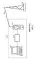
- FIG. 1 is a functional block diagram illustrating a wireless data connection.
- a terminal equipment (TE) 10 may be a laptop, palmtop, or other conventional computing device.
- the TE 10 is coupled to a wireless communication device, such as a mobile telephone (MT) 12, usually through a mobile system modem (MSM) 14.
- MT mobile telephone
- MSM mobile system modem
- the MSM 14 may be incorporated into the TE 10 or into the MT 12.
- the TE 10, MT 12 and MSM 14 may conveniently be collectively characterized as a mobile station (MS) 16, as indicated by the dashed lines in FIG. 1 .
- the MS 16 may be an integrated device comprising a TE 10, an MT 12, and an MSM 14.
- the wireless communication system of FIG. 1 also includes a base station transceiver system (BTS) 18.
- BTS base station transceiver system
- the BTS 18 communicates with the MS 16 via a wireless communication link 20.
- Such implementations may take advantage of the fact that in most communication sessions the MS 16 receives much more data from the BTS 18 (forward channel communication) than the MS 16 transmits to the BTS 18 (reverse channel communication). Thus, less bandwidth may normally be assigned for reverse channel communication, with additional bandwidth assigned as the amount of data to be transmitted increases.
- the BTS 18 is configured to assign a reverse supplemental channel (R-SCH) with an assigned data rate and burst length to an MS 16 in response to a supplemental channel request message (SCRM) from the MS 16.
- R-SCH reverse supplemental channel
- SCRM Supplemental channel request message
- the MS 16 and the BTS 18 will negotiate a maximum agreed R-SCH data rate.
- the negotiated rate may be based on various factors, such as the maximum rate the MS 16 can support and the amount of available power resources of the MS 16 to be allocated to reverse channel communication.
- the MS 16 sends a non-zero length SCRM to the BTS 18 to indicate a R-SCH is needed in response to certain triggering events.
- the MS 16 may send an SCRM when it does not have an R-SCH assignment and a certain number of bytes are buffered for transmission to the BTS 18.
- the MS 16 may also send an SCRM when the assigned R-SCH data rate is too high or too low for the current operating conditions.
- the MS 16 may also send a zero-length SCRM to cancel a R-SCH.
- the MS 16 may request a R-SCH.
- the BTS 18 may assign a R-SCH and notify the MS 16 of the assignment with an extended supplemental channel assignment message (ESCAM) or a universal handoff direction message (UHDM).
- ESCAM extended supplemental channel assignment message
- UHDM universal handoff direction message
- the BTS 18 may not grant the requested data rate or may not grant the request at all.
- the BTS 18 may also send a retry delay message to the MS 16.
- the MS 16 may be configured not to send a request until a delay period has elapsed from the last SCRM, even though a triggering event has occurred. For example, an MS 16 may be configured not to send an SCRM more than once a second. Even with this restriction, however, an MS 16 may transmit too many SCRMs, including SCRMs which are not likely to result in a more optimal assignment of R-SCHs by the BTS 18 . In addition, when the amount of data to be transmitted exceeds the capacity of a currently assigned R-SCH, there can be a significant delay between the termination of the current R-SCH burst and the start of a subsequent R-SCH.
- the system and method described herein are directed to controlling transmission of supplemental channel request messages (SCRM) by a wireless communication device as defined in independent claims 1 and 12.
- SCRM supplemental channel request messages
- the system may be configured to prevent transmission of a SCRM in response to a predetermined triggering event until a fixed period of time has elapsed since the last transmission of a SCRM in response to the predetermined triggering event.
- FIG. 1 is a functional block diagram of wireless link of an MS with a BTS.
- FIG. 2 is a functional block diagram of a MS of an embodiment.
- FIG. 3 is a timing diagram illustrating the operation of an embodiment.
- FIG. 4 is a timing diagram illustrating the operation of an embodiment.
- FIG. 5 is a timing diagram illustrating the operation of an embodiment.
- FIG. 6 is a timing diagram illustrating the operation of an embodiment.
- FIG. 7 is a timing diagram illustrating the operation of an embodiment.
- FIG. 8 is a flow chart illustrating the operation of an embodiment.
- FIG. 9 is a flow chart illustrating the operation of an embodiment.
- FIG. 10 is a flow chart illustrating the operation of an embodiment.
- the system and method described herein is directed to efficient transmission of SCRMs in a mobile communications device.
- FIG. 1 illustrates the simplified general wireless connection that supports the communication process.
- the MS 16 includes a central processing unit (CPU) 22 and a memory 24, which controls operation of the system.
- CPU central processing unit
- memory which controls operation of the system.
- CPU is intended to encompass any processing device, alone or in combination with other devices such as a memory (not shown), that is capable of operating the MS 16 or a portion thereof. This includes microprocessors, embedded controllers, application specific integrated circuits (ASICs), digital signal processors (DSPs), state machines, dedicated discrete hardware, and the like.
- ASICs application specific integrated circuits
- DSPs digital signal processors
- state machines dedicated discrete hardware, and the like.
- the system and method described herein are not limited by the specific hardware component selected to implement the CPU 22 .
- the CPU 22 may be incorporated into other components of the MS 16 , including the MSM 14 , the MT 12 or the TE 10 .
- the memory 24 which may include both read-only memory (ROM) and random-access memories (RAM), provides instructions and data to the CPU 22 .
- a portion of the memory 24 may also include non-volatile random-access memory.
- the MS 16 also includes a transmitter 30 and a receiver 32 to allow transmission and reception of data, such as audio communication and programming data, between the MS 16 and a remote location, such as a base transceiver station (BTS) 18 (see FIG. 1 ).
- a base transceiver station BTS
- the transmitter 30 and the receiver 32 may be combined into a transceiver 34 .
- An antenna 36 is electrically coupled to the transceiver 34 .
- the operation of the transmitter 30 , receiver 32 , and antenna 36 is well-known in the art and need not be described herein.
- the MS 16 also includes an SCRM controller 54 , which may typically be implemented by the CPU 22 , executing instructions stored in the memory 24 .
- the MS 16 may use the SCRM controller 54 to generate control signals to control the transmission of SCRMs by the MS 16 .
- the MS 16 also includes an SCRM timer 56 , and an event timer 58 , both of which may typically be implemented by the CPU 52 or the SCRM controller 54 .
- the SCRM controller 54 uses the timers 56, 58 to control SCRM transmissions.
- bus system 60 which may include a power bus, control bus and status signal bus in addition to a data bus.
- bus system 60 may include a power bus, control bus and status signal bus in addition to a data bus.
- bus system 60 may include a power bus, control bus and status signal bus in addition to a data bus.
- the MS 16 may contain other components, such as a battery (not shown), and input/output devices (not shown), and that the components can be arranged in various configurations.
- FIG. 2 illustrates the TE 10 coupled to the MT 12 via the MSM 14 , as also illustrated in Fig. 1 .
- the TE 10 may be coupled directly to the bus system 60 if the TE 10 , MT 12 and MSM 14 are integrated into the MS 16.
- the system and method described herein are not limited to the specific configuration and arrangement of components shown.
- the SCRM controller 54 may use the timers 56 , 58 to determine when to generate control signals to control the transmission of SCRMs by the MS 16 .
- the SCRM timer 56 may be started or restarted when the MS 16 transmits an SCRM for a non-zero R-SCH.
- the SCRM timer 56 may be cancelled when a fixed time period has elapsed or when the MS 16 receives either an ESCAM or a UHDM with a non-zero R-SCH assignment.
- the SCRM controller 54 may be configured to disable the ability of the MS 16 to transmit an SCRM for a non-zero R-SCH when the SCRM timer 56 is running.
- time period may be fixed at the factory, may be fixed by the user, may be fixed by the SCRM controller 54 in response to RF conditions, or the amount of traffic on the channel, or may be fixed in response to a signal received by the MS 16 .
- the event timer 58 may be started or restarted whenever a predetermined event occurs.
- the predetermined event may be transmission of an SCRM by the MS 16 in response to a particular triggering event.
- the predetermined event may also be the start of an assigned R-SCH burst.
- the event timer 58 may also be started or restarted when one of a plurality of predetermined events occurs.
- the event timer 58 may be cancelled when a fixed time period has elapsed, when a current R-SCH burst ends, or when an ESCAM to cancel an R-SCH is received and there is no current R-SCH burst active.
- the time period may be fixed at the factory, may be fixed by the user, may be fixed by the SCRM controller 54 in response to RF conditions or traffic on the channel, or may be fixed in response to a signal received by the MS 16 .
- the fixed time period when the event timer 58 expires need not be the same fixed time period when the SCRM timer 56 expires.
- the SCRM controller 54 may be configured to disable the ability of the MS 16 to transmit an SCRM for a non-zero R-SCH in response to a predetermined triggering event when the event timer 58 is running.
- the SCRM controller 54 may also be configured to disable the ability of the MS 16 to transmit an SCRM for a non-zero R-SCH in response to any one of a plurality of predetermined triggering events when the event timer 58 is running.
- the SCRM controller 54 may be configured to generate control signals to cause the transmission of a burst extension SCRM for a non-zero R-SCH when the MS 16 determines the current R-SCH burst is not adequate for current data needs, and before the current R-SCH burst ends. For example, the MS 16 may determine that the number of bytes or frames remaining to be transmitted exceeds the number of bytes or frames that can be transmitted in the current R-SCH burst. In response to a burst extension SCRM, the BTS 18 may assign a new R-SCH burst, or may deny the request.
- burst extension SCRMs helps to reduce the time between expiration of the current R-SCH burst and the start of the next R-SCH burst.
- the newly assigned R-SCH burst will either overlap or be contiguous with the current R-SCH burst.
- the transmission of a burst extension SCRM will not be one of the predetermined events that results in the starting or restarting of the event timer 58 .
- the SCRM controller 54 may disable the ability of the MS 16 to transmit a burst extension SCRM when the SCRM timer 56 is running.
- the ability of the MS 16 to transmit a burst extension SCRM may also be further restricted. For example, it may be prohibited until the burst length remaining in the current R-SCH is below a predetermined threshold value, such as a certain number of remaining available frames or until a fixed time period before the end of the current R-SCH burst.
- the predetermined threshold value may be set at the factory, set by the user, set in response to RF conditions or traffic on the channel, or set in response to a signal received by the MS 16 .
- burst extension gap The period in which a burst extension SCRM may be transmitted to request extension of a current R-SCH burst, assuming other conditions permit transmission of a burst extension SCRM, may be referred to as the burst extension gap. Additional timers may be employed to implement additional restrictions on the ability of the MS 16 to transmit a burst extension SCRM.
- the SCRM controller 54 may be configured to disable the ability of the MS 16 to transmit an SCRM for a non-zero R-SCH (whether to request a burst extension or in response to another triggering event) during the time period after an ESCAM or UHDM assigning a non-zero R-SCH is received and before the assigned R-SCH burst starts or another message canceling the assigned non-zero R-SCH is received.
- the SCRM controller 54 may be readily implemented as a series of instructions stored in the memory 24 and executed by the CPU 22 . Thus, minor software modifications to existing hardware will allow the implementation of the MS 16 .
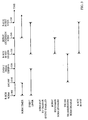
- FIG. 3 is a timing diagram illustrating the operation of an embodiment of the MS 16 .
- the MS 16 is configured to start or restart the event timer 58 in response to the following predetermined events: the MS 16 transmits a non-zero R-SCH SCRM because there is no current R-SCH burst and the amount of data to be transmitted to the BTS 18 exceeds a threshold value; the MS 16 transmits a non-zero R-SCH SCRM because the data rate of the current R-SCH burst is not optimal; and an R-SCH burst starts.
- the SCRM controller 54 is configured to disable the ability of the MS 16 to transmit a non-zero R-SCH SCRM in response to the following triggering events when the event timer 58 is running: there is no current R-SCH burst and the amount of data to be transmitted to the BTS 18 exceeds a threshold value; and the data rate of the current R-SCH burst is not optimal.
- the MS 16 sends a non-zero R-SCH SCRM because the amount of data to be transmitted to the BTS 18 exceeds a threshold value.
- the SCRM timer 56 is started because a non-zero R-SCH SCRM was transmitted.
- the event timer 58 is started because one of the predetermined events has occurred - a non-zero R-SCH SCRM was transmitted when no current R-SCH burst was active because the amount of data to be transmitted to the BTS 18 exceeded a threshold value.
- the SCRM controller 54 disables the ability of the MS 16 to transmit an SCRM for a non-zero R-SCH because the SCRM timer 56 is running. During this time period, the SCRM controller 54 also disables the ability of the MS 16 to transmit an R-SCH SCRM in response to one of the predetermined triggering events because the event timer 58 is running.
- the MS 16 receives an ESCAM assigning a non-zero R-SCH burst.
- the SCRM timer 56 is stopped.
- the event timer 58 continues to run.
- the SCRM controller 54 disables the ability of the MS 16 to transmit an SCRM for a non-zero R-SCH in response to one of the predetermined triggering events because the event timer 58 is running.
- the SCRM controller 54 disables the ability of the MS 16 to transmit any SCRM for a non-zero R-SCH because an ESCAM has been received assigning a non-zero R-SCH burst and the assigned burst has not yet started. This is illustrated in FIG. 3 as the ESCAM Transmission/SCRM disable.
- the fixed time period for the event timer 58 to operate expires.
- the event timer 58 stops.
- the SCRM controller 54 disables the ability of the MS 16 to transmit an SCRM for a non-zero R-SCH because a non-zero R-SCH burst has been assigned but has not yet started. As noted above, this is illustrated in FIG. 3 as the ESCAM Transmission/SCRM disable.
- the assigned R-SCH burst starts.
- the event timer 58 is started to prevent the MS 16 from instantly transmitting an SCRM because the MS 16 is not satisfied with the assigned data rate.
- the SCRM timer 56 remains stopped.
- the ability of the MS 16 to transmit an SCRM for a non-zero R-SCH in response to one of the predetermined triggering events is disabled because the event timer 58 is running.
- the ability of the MS 16 to transmit a burst extension SCRM for a non-zero R-SCH is enabled because the SCRM timer 56 is not running and the current R-SCH burst has started.
- the ability of the MS 16 to transmit a burst extension SCRM for a non-zero R-SCH may continue to be disabled because other criteria for enablement may not be satisfied. For example, the number of available frames in the current R-SCH burst may exceed a threshold level. In other words, the current R-SCH burst may not be in the burst extension gap.
- the MS 16 determines that the current R-SCH burst is insufficient to meet the data transmission needs of the MS 16 .
- the SCRM controller 54 generates control signals to cause the MS 16 to transmit a burst extension SCRM for a non-zero R-SCH.
- the SCRM timer 56 is started.
- the ability of the MS 16 to transmit an SCRM for a non-zero R-SCH is disabled because the SCRM timer 56 is running.
- the event timer 58 is not re-started, since the SCRM was for a burst extension, and was not due to a triggering event.
- the current R-SCH burst ends.
- the event timer 58 is turned off. As illustrated, the event timer 58 would also be turned off because the fixed time period for the event timer 58 to operate expired.
- the end of the current R-SCH burst will not necessarily coincide with the expiration of the fixed period of time for the event timer 58 to operate.
- the ability of the MS 16 to transmit an SCRM for a non-zero R-SCH for any reason is disabled because the SCRM timer 56 is running.
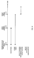
- FIG. 4 is a timing diagram illustrating the operation of an embodiment when no response is received to a non-zero R-SCH SCRM transmitted in response to one of the predetermined triggering events.
- the MS 16 transmits an SCRM for a non-zero length R-SCH in response to one of the predetermined triggering events. Both timers 56 , 58 are started. Between time 410 and 420 , the MS 16 cannot transmit an SCRM for a non-zero R-SCH because the SCRM timer 56 is running.
- the SCRM timer 56 expires.
- the event timer 58 expires.
- the MS 16 cannot transmit an SCRM for a non-zero length R-SCH in response to one of the predetermined triggering events because the event timer 58 is running.
- the MS 16 cannot transmit a burst extension SCRM because there is no current R-SCH burst active.
- the MS 16 can transmit an SCRM for a non-zero R-SCH in response to one of the predetermined events because both timers 56 , 58 have expired and no message, such as an ESCAM or UHDM, assigning a non-zero R-SCH burst has been received.
- the MS 16 cannot transmit a burst extension SCRM because there is no current R-SCH burst active.
- FIG. 4 does not show any time period during which the MS 16 can transmit a burst extension SCRM.
- FIG. 5 is a timing diagram illustrating the operation of an embodiment when a response to a burst extension SCRM is not received.
- the SCRM timer 56 is off, the event timer 58 is running and a current R-SCH burst is active.
- the MS 16 cannot transmit a non-zero SCRM in response to one of the predetermined triggering events because the event timer 58 is running.
- the MS 16 cannot transmit a burst extension SCRM because the current burst is longer than the burst extension gap, because, for example, the number of frames remaining in the current R-SCH may be above a threshold value.
- the number of available frames in the current R-SCH burst drops below a threshold value and, because the SCRM timer 56 is not running, the ability of the MS 16 to transmit a burst extension SCRM is enabled.
- the time between time 520 and the end of the current burst at time 540 is the burst extension gap.
- the MS 16 determines that the current burst length is insufficient and transmits a burst extension SCRM.
- the SCRM timer 56 is started.
- the event timer 58 is not reset because the SCRM was not due to one of the predetermined triggering events.
- the MS 16 cannot transmit a non-zero R-SCH SCRM, whether due to one of the predetermined triggering events or to request a burst extension R-SCH, because the SCRM timer 56 is running.
- the current R-SCH burst ends and, in response, the event timer 58 is stopped.
- the MS 16 cannot transmit a non-zero R-SCH SCRM, whether due to a predetermined triggering event or to request a burst extension R-SCH, because the SCRM timer 56 is running.
- the ability of the MS 16 to transmit a burst extension SCRM is disabled for the additional reason that there is no burst extension gap because there is no current R-SCH burst.
- the SCRM timer 56 expires and the ability of the system to transmit a non-zero R-SCH SCRM in response to one of the predetermined triggering events is enabled because both timers 56 , 58 are stopped and no message assigning a non-zero R-SCH burst has been received.
- the MS 16 transmits an SCRM for a non-zero R-SCH in response to a predetermined triggering event. In response, both timers 56 , 58 are started.
- FIG. 6 is a timing diagram illustrating the operation when the burst length of an assigned R-SCH is less than the burst extension gap.
- the MS 16 transmits a non-zero R-SCH SCRM in response to one of the predetermined triggering events. In response, both timers 56 , 58 are started. Between time 610 and 620 the MS 16 cannot transmit a non-zero R-SCH SCRM.
- an ESCAM is received assigning a non-zero R-SCH and the SCRM timer 56 is stopped.
- the burst length of the assigned R-SCH is less than the burst extension gap.
- the MS 16 cannot transmit a non-zero R-SCH SCRM because a R-SCH burst has been assigned, but has not yet started.
- the MS 16 cannot transmit a non-zero R-SCH SCRM in response to one of the predetermined triggering events for the additional reason that the event timer 58 is running.
- the assigned R-SCH burst starts.
- the event timer 58 is restarted.
- the MS 16 will almost instantly transmit a burst extension SCRM because the burst length is less than the burst extension gap and the SCRM timer 56 is not running. This is illustrated in FIG. 6 as occurring at time 631 . Transmission of the burst extension SCRM will cause the SCRM timer 56 to start.
- the current burst terminates, which results in the stopping of the event timer 58 .
- FIG. 7 is a timing diagram illustrating the operation when a scheduled R-SCH burst is cancelled.
- a non-zero R-SCH SCRM is transmitted in response to a predetermined triggering event. Both timers 56 , 58 are started.
- an ESCAM is received assigning a non-zero R-SCH.
- the SCRM timer 56 is stopped.
- the MS 16 cannot transmit a non-zero R-SCH SCRM because a non-zero R-SCH burst has been assigned but has not started. This is illustrated in FIG. 7 as the ESCAM Transmission/SCRM disable.
- the event timer 58 is running so a non-zero R-SCH SCRM due to one of the predetermined triggering events is not permitted.
- an ESCAM is received which cancels the scheduled R-SCH burst.
- the event timer 58 is stopped and the MS 16 is permitted to transmit a non-zero SCRM in response to a predetermined triggering event.
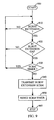
- FIG. 8 is a flow chart illustrating the operation of an embodiment when a predetermined triggering event occurs.
- the MS 16 is started.
- the MS 16 determines whether a non-zero R-SCH SCRM is desired due to a predetermined triggering event. If the answer is YES, the MS 16 proceeds to step 820 . If the answer is NO, the MS 16 returns to step 810 .
- step 820 the MS 16 determines whether the SCRM timer 56 is running. If the answer is YES, the MS 16 returns to step 810 because a non-zero R-SCH SCRM may not be transmitted while the SCRM timer 56 is running. If the answer is NO, the MS 16 proceeds to step 830 .
- the MS 16 determines whether the event timer is running. If the answer is YES, the MS 16 returns to step 810 because a non-zero R-SCH SCRM in response to a predetermined triggering event may not be transmitted while the event timer 58 is running. If the answer is NO, the MS 16 proceeds to step 840 .
- the MS 16 determines whether a message that a non-zero R-SCH burst is scheduled for the future has been received. If the answer is YES, the MS 16 returns to step 810 because a non-zero R-SCH SCRM may not be transmitted if a non-zero R-SCH burst is scheduled but has not yet started. If the answer is NO, the MS 16 proceeds to step 850 .
- the MS 16 transmits a SCRM requesting a non-zero R-SCH in response to the predetermined triggering event and proceeds to step 860 .
- the MS 16 resets the SCRM and event timers 56 and 58 and proceeds to step 870 where processing of the predetermined triggering event by the MS 16 terminates.
- FIG. 9 is a flow chart illustrating the operation when the MS 16 determines that the current R-SCH burst is insufficient to transmit the current data needs of the MS 16 .
- the MS 16 is started.
- the MS 16 determines whether a burst extension is desired. In an exemplary embodiment, the answer to this question will always be NO if there is no current burst. If the answer at step 910 is NO, the MS 16 returns to step 910 . If the answer at step 910 is YES, the MS 16 proceeds to step 920 .
- the MS 16 determines whether the current burst is in the burst extension gap. If the answer at step 920 is NO, the MS 16 returns to step 910 . If the answer at step 920 is YES, the MS 16 proceeds to step 930 .
- step 930 the MS 16 determines whether the SCRM timer 56 is running. If the answer at step 930 is YES, the MS 16 returns to step 910 . If the answer at step 930 is NO, the MS 16 proceeds to step 940 .
- the MS 16 transmits a non-zero burst extension SCRM and proceeds to step 950 .
- the MS 16 starts or restarts the SCRM timer 56 and proceeds to step 960 , where processing of the burst extension request by the MS 16 terminates.
- FIG. 10 is a flow chart illustrating the operation of when the MS 16 determines that a current R-SCH burst is not optimal.
- the MS 16 is started.
- the MS 16 determines whether a burst extension is desired. In an exemplary embodiment, the answer to this question will always be NO if there is no current R-SCH burst. If the answer at step 1010 is NO, the MS 16 proceeds to step 1020 . If the answer at step 1010 is YES, the MS 16 proceeds to step 1030 .
- step 1020 the MS 16 determines whether a different R-SCH burst is desired. If the answer at step 1020 is NO, the MS 16 returns to step 1010 . If the answer at step 1020 is YES, the MS 16 proceeds to step 1070 .
- the MS 16 determines whether a current burst is in the burst extension gap. If the answer at step 1030 is YES, the MS 16 proceeds to step 1040 . If the answer at step 1030 is NO, the MS 16 proceeds to step 1020 .
- the MS 16 determines whether the SCRM timer 56 is running. If the answer at step 1040 is YES, the MS 16 returns to step 1010 . If the answer at step 1040 is NO, the MS 16 proceeds to step 1050 .
- the MS 16 transmits a non-zero burst extension SCRM and proceeds to step 1060 .
- the MS 16 starts or restarts the SCRM timer 56 and proceeds to step 2010 , where processing terminates.
- step 1070 the MS 16 determines whether the event timer 58 is running. If the answer at step 1070 is YES, the MS 16 returns to step 1010 . If the answer at step 1070 is NO, the MS 16 proceeds to step 1080 .
- step 1080 the MS 16 determines whether the SCRM timer 56 is running. If the answer at step 1080 is YES, the MS 16 returns to step 1010 . If the answer at step 1080 is NO, the MS 16 proceeds to step 1090.
- the MS 16 transmits a non-zero R-SCH SCRM and proceeds to step 2000 .
- the MS 16 starts or restarts the event timer 58 and proceeds to step 1060 .
- the MS 16 starts or restarts the SCRM timer 56 and proceeds to step 2010 , where processing terminates.
Landscapes
- Engineering & Computer Science (AREA)
- Computer Networks & Wireless Communication (AREA)
- Signal Processing (AREA)
- Quality & Reliability (AREA)
- Mobile Radio Communication Systems (AREA)
Abstract
Description
- The technical field generally relates to the field of wireless communications. More particularly, the technical field relates to a system and method for efficient transmission of a supplemental channel request message (SCRM) for a reverse supplemental channel (R-SCH) in a wireless communications device.
- Recent advances in wireless communications and the rapid expansion of use of the Internet have greatly increased the demand for mobile computing. Technologies for allowing a large number of system users to share a communication system, such as Code Division Multiple Access (CDMA) technology, have played a critical role in meeting that demand.
- CDMA is a digital radio-frequency (RF) technique defined in the Telecommunications Industry Association/Electronics Industries Association Interim Standard-95, entitled "MOBILE STATION-BASE STATION COMPATIBILITY STANDARD FOR DUAL-MODE WIDEBAND SPREAD SPECTRUM CELLULAR SYSTEM," which was published in July 1993 and which is incorporated herein by reference.
- CDMA communication devices are assigned a unique code and each device uses its code to spread its communication signals across a common spread-spectrum bandwidth. As long as the communication device has the correct code, it can successfully detect and select its signal from among other signals concurrently transmitted over the same bandwidth.
- Other multiple access techniques include time division multiple access (TDMA) and frequency division multiple access (FDMA) systems. There are also analog frequency modulation (FM) based wireless communication systems, such as the Advanced Mobile Phone System (AMPS). In addition, many wireless communication devices combine communications capabilities with global position system (GPS) techniques. Some wireless communication systems are capable of operating using multiple techniques, such as CDMA and GPS, or on different frequency bands, such as cellular or Personal Communication Services (PCS) bands.
- The increased reliability of mobile communications has led to a demand for remote wireless computing where a computing device, such as a laptop computer or palmtop computer, is remotely coupled to a computer network (e.g., the Internet) via the mobile telephone.
-
FIG. 1 is a functional block diagram illustrating a wireless data connection. InFIG. 1 a terminal equipment (TE) 10 may be a laptop, palmtop, or other conventional computing device. TheTE 10 is coupled to a wireless communication device, such as a mobile telephone (MT) 12, usually through a mobile system modem (MSM) 14. TheMSM 14 may be incorporated into theTE 10 or into theMT 12. - The
TE 10,MT 12 andMSM 14 may conveniently be collectively characterized as a mobile station (MS) 16, as indicated by the dashed lines inFIG. 1 . In fact, theMS 16 may be an integrated device comprising aTE 10, anMT 12, and anMSM 14. - The wireless communication system of
FIG. 1 also includes a base station transceiver system (BTS) 18. TheBTS 18 communicates with theMS 16 via awireless communication link 20. - To establish a communication link between the
MS 16 and theBTS 18, communication signals are exchanged. Various protocols and standards provide a framework for implementing a wireless data connection. The actual implementation of hardware and software within that framework is left to the discretion of the designer. - Such implementations may take advantage of the fact that in most communication sessions the
MS 16 receives much more data from the BTS 18 (forward channel communication) than theMS 16 transmits to the BTS 18 (reverse channel communication). Thus, less bandwidth may normally be assigned for reverse channel communication, with additional bandwidth assigned as the amount of data to be transmitted increases. In one such implementation theBTS 18 is configured to assign a reverse supplemental channel (R-SCH) with an assigned data rate and burst length to anMS 16 in response to a supplemental channel request message (SCRM) from theMS 16. Such an implementation is described, for example, in "Evolution of Wireless Data Services: IS-95 to . - Typically, at call setup the
MS 16 and theBTS 18 will negotiate a maximum agreed R-SCH data rate. The negotiated rate may be based on various factors, such as the maximum rate theMS 16 can support and the amount of available power resources of theMS 16 to be allocated to reverse channel communication. TheMS 16 sends a non-zero length SCRM to theBTS 18 to indicate a R-SCH is needed in response to certain triggering events. - For example, the
MS 16 may send an SCRM when it does not have an R-SCH assignment and a certain number of bytes are buffered for transmission to the BTS 18. The MS 16 may also send an SCRM when the assigned R-SCH data rate is too high or too low for the current operating conditions. The MS 16 may also send a zero-length SCRM to cancel a R-SCH. - The
MS 16 may request a R-SCH. In response, the BTS 18 may assign a R-SCH and notify theMS 16 of the assignment with an extended supplemental channel assignment message (ESCAM) or a universal handoff direction message (UHDM). Moreover, the BTS 18 may not grant the requested data rate or may not grant the request at all. In addition, there may be a delay in granting the request. The BTS 18 may also send a retry delay message to theMS 16. - To prevent flooding of the BTS 18 with SCRMs, the
MS 16 may be configured not to send a request until a delay period has elapsed from the last SCRM, even though a triggering event has occurred. For example, an MS 16 may be configured not to send an SCRM more than once a second. Even with this restriction, however, anMS 16 may transmit too many SCRMs, including SCRMs which are not likely to result in a more optimal assignment of R-SCHs by the BTS 18. In addition, when the amount of data to be transmitted exceeds the capacity of a currently assigned R-SCH, there can be a significant delay between the termination of the current R-SCH burst and the start of a subsequent R-SCH. - Therefore, it can be appreciated that there is a significant need for an efficient system and method for controlling transmission of an SCRM for a R-SCH in a wireless communication device.
- The system and method described herein are directed to controlling transmission of supplemental channel request messages (SCRM) by a wireless communication device as defined in
independent claims 1 and 12. In one embodiment, the system may be configured to prevent transmission of a SCRM in response to a predetermined triggering event until a fixed period of time has elapsed since the last transmission of a SCRM in response to the predetermined triggering event. -
FIG. 1 is a functional block diagram of wireless link of an MS with a BTS. -
FIG. 2 is a functional block diagram of a MS of an embodiment. -
FIG. 3 is a timing diagram illustrating the operation of an embodiment. -
FIG. 4 is a timing diagram illustrating the operation of an embodiment. -
FIG. 5 is a timing diagram illustrating the operation of an embodiment. -
FIG. 6 is a timing diagram illustrating the operation of an embodiment. -
FIG. 7 is a timing diagram illustrating the operation of an embodiment. -
FIG. 8 is a flow chart illustrating the operation of an embodiment. -
FIG. 9 is a flow chart illustrating the operation of an embodiment. -
FIG. 10 is a flow chart illustrating the operation of an embodiment. - The system and method described herein is directed to efficient transmission of SCRMs in a mobile communications device.
- As noted above, a number of different standards exist to govern wireless data communication. These standards may be implemented in a number of different ways to provide some flexibility to the designer.
FIG. 1 illustrates the simplified general wireless connection that supports the communication process. - A system is embodied in an
MS 16 illustrated in the functional block ofFIG. 2 . TheMS 16 includes a central processing unit (CPU) 22 and amemory 24, which controls operation of the system. Those skilled in the art will appreciate that the term "CPU" is intended to encompass any processing device, alone or in combination with other devices such as a memory (not shown), that is capable of operating theMS 16 or a portion thereof. This includes microprocessors, embedded controllers, application specific integrated circuits (ASICs), digital signal processors (DSPs), state machines, dedicated discrete hardware, and the like. The system and method described herein are not limited by the specific hardware component selected to implement the CPU 22. Moreover, after reviewing the specification one of skill in the art will recognize that the CPU 22 may be incorporated into other components of theMS 16, including theMSM 14, theMT 12 or theTE 10. - The
memory 24, which may include both read-only memory (ROM) and random-access memories (RAM), provides instructions and data to the CPU 22. A portion of thememory 24 may also include non-volatile random-access memory. - The
MS 16 also includes atransmitter 30 and areceiver 32 to allow transmission and reception of data, such as audio communication and programming data, between theMS 16 and a remote location, such as a base transceiver station (BTS) 18 (seeFIG. 1 ). As mentioned above, thetransmitter 30 and thereceiver 32 may be combined into atransceiver 34. Anantenna 36 is electrically coupled to thetransceiver 34. The operation of thetransmitter 30,receiver 32, andantenna 36 is well-known in the art and need not be described herein. - The
MS 16 also includes anSCRM controller 54, which may typically be implemented by the CPU 22, executing instructions stored in thememory 24. TheMS 16 may use theSCRM controller 54 to generate control signals to control the transmission of SCRMs by theMS 16. - The
MS 16 also includes anSCRM timer 56, and anevent timer 58, both of which may typically be implemented by the CPU 52 or theSCRM controller 54. As will be described in detail below, theSCRM controller 54 uses thetimers - The various components of the
MS 16 are coupled together by abus system 60 which may include a power bus, control bus and status signal bus in addition to a data bus. For the sake of clarity, however, the various buses are illustrated inFig. 2 as thebus system 60. - Those of skill in the art will recognize that the
MS 16 may contain other components, such as a battery (not shown), and input/output devices (not shown), and that the components can be arranged in various configurations. For example,FIG. 2 illustrates theTE 10 coupled to theMT 12 via theMSM 14, as also illustrated inFig. 1 . However, theTE 10 may be coupled directly to thebus system 60 if theTE 10,MT 12 andMSM 14 are integrated into theMS 16. The system and method described herein are not limited to the specific configuration and arrangement of components shown. - The
SCRM controller 54 may use thetimers MS 16. TheSCRM timer 56 may be started or restarted when theMS 16 transmits an SCRM for a non-zero R-SCH. TheSCRM timer 56 may be cancelled when a fixed time period has elapsed or when theMS 16 receives either an ESCAM or a UHDM with a non-zero R-SCH assignment. TheSCRM controller 54 may be configured to disable the ability of theMS 16 to transmit an SCRM for a non-zero R-SCH when theSCRM timer 56 is running. After reviewing this specification, one of skill in the art will recognize that the time period may be fixed at the factory, may be fixed by the user, may be fixed by theSCRM controller 54 in response to RF conditions, or the amount of traffic on the channel, or may be fixed in response to a signal received by theMS 16. - The
event timer 58 may be started or restarted whenever a predetermined event occurs. For example, the predetermined event may be transmission of an SCRM by theMS 16 in response to a particular triggering event. The predetermined event may also be the start of an assigned R-SCH burst. Theevent timer 58 may also be started or restarted when one of a plurality of predetermined events occurs. - The
event timer 58 may be cancelled when a fixed time period has elapsed, when a current R-SCH burst ends, or when an ESCAM to cancel an R-SCH is received and there is no current R-SCH burst active. After reviewing this specification, one of skill in the art will recognize that the time period may be fixed at the factory, may be fixed by the user, may be fixed by theSCRM controller 54 in response to RF conditions or traffic on the channel, or may be fixed in response to a signal received by theMS 16. The fixed time period when theevent timer 58 expires need not be the same fixed time period when theSCRM timer 56 expires. - The
SCRM controller 54 may be configured to disable the ability of theMS 16 to transmit an SCRM for a non-zero R-SCH in response to a predetermined triggering event when theevent timer 58 is running. TheSCRM controller 54 may also be configured to disable the ability of theMS 16 to transmit an SCRM for a non-zero R-SCH in response to any one of a plurality of predetermined triggering events when theevent timer 58 is running. - In an embodiment of the invention, the
SCRM controller 54 may be configured to generate control signals to cause the transmission of a burst extension SCRM for a non-zero R-SCH when theMS 16 determines the current R-SCH burst is not adequate for current data needs, and before the current R-SCH burst ends. For example, theMS 16 may determine that the number of bytes or frames remaining to be transmitted exceeds the number of bytes or frames that can be transmitted in the current R-SCH burst. In response to a burst extension SCRM, theBTS 18 may assign a new R-SCH burst, or may deny the request. Use of burst extension SCRMs helps to reduce the time between expiration of the current R-SCH burst and the start of the next R-SCH burst. In an exemplary embodiment, the newly assigned R-SCH burst will either overlap or be contiguous with the current R-SCH burst. In an exemplary embodiment, the transmission of a burst extension SCRM will not be one of the predetermined events that results in the starting or restarting of theevent timer 58. - The
SCRM controller 54 may disable the ability of theMS 16 to transmit a burst extension SCRM when theSCRM timer 56 is running. The ability of theMS 16 to transmit a burst extension SCRM may also be further restricted. For example, it may be prohibited until the burst length remaining in the current R-SCH is below a predetermined threshold value, such as a certain number of remaining available frames or until a fixed time period before the end of the current R-SCH burst. The predetermined threshold value may be set at the factory, set by the user, set in response to RF conditions or traffic on the channel, or set in response to a signal received by theMS 16. The period in which a burst extension SCRM may be transmitted to request extension of a current R-SCH burst, assuming other conditions permit transmission of a burst extension SCRM, may be referred to as the burst extension gap. Additional timers may be employed to implement additional restrictions on the ability of theMS 16 to transmit a burst extension SCRM. - In general, the
SCRM controller 54 may be configured to disable the ability of theMS 16 to transmit an SCRM for a non-zero R-SCH (whether to request a burst extension or in response to another triggering event) during the time period after an ESCAM or UHDM assigning a non-zero R-SCH is received and before the assigned R-SCH burst starts or another message canceling the assigned non-zero R-SCH is received. - The
SCRM controller 54 may be readily implemented as a series of instructions stored in thememory 24 and executed by the CPU 22. Thus, minor software modifications to existing hardware will allow the implementation of theMS 16. - For purposes of brevity, the operation of the
MS 16 to efficiently transmit SCRMs will be illustrated using a limited number of examples. To simplify the illustrations, events are generally shown as occurring at evenly-spaced time intervals. However, events may occur at different time intervals and in different orders than as illustrated. -
FIG. 3 is a timing diagram illustrating the operation of an embodiment of theMS 16. In the embodiment illustrated inFIG. 3 , theMS 16 is configured to start or restart theevent timer 58 in response to the following predetermined events: theMS 16 transmits a non-zero R-SCH SCRM because there is no current R-SCH burst and the amount of data to be transmitted to theBTS 18 exceeds a threshold value; theMS 16 transmits a non-zero R-SCH SCRM because the data rate of the current R-SCH burst is not optimal; and an R-SCH burst starts. TheSCRM controller 54 is configured to disable the ability of theMS 16 to transmit a non-zero R-SCH SCRM in response to the following triggering events when theevent timer 58 is running: there is no current R-SCH burst and the amount of data to be transmitted to theBTS 18 exceeds a threshold value; and the data rate of the current R-SCH burst is not optimal. - At time 300, no R-SCH is active and the
MS 16 sends a non-zero R-SCH SCRM because the amount of data to be transmitted to theBTS 18 exceeds a threshold value. TheSCRM timer 56 is started because a non-zero R-SCH SCRM was transmitted. Theevent timer 58 is started because one of the predetermined events has occurred - a non-zero R-SCH SCRM was transmitted when no current R-SCH burst was active because the amount of data to be transmitted to theBTS 18 exceeded a threshold value. Betweentime 300 and 310, theSCRM controller 54 disables the ability of theMS 16 to transmit an SCRM for a non-zero R-SCH because theSCRM timer 56 is running. During this time period, theSCRM controller 54 also disables the ability of theMS 16 to transmit an R-SCH SCRM in response to one of the predetermined triggering events because theevent timer 58 is running. - At
time 310 theMS 16 receives an ESCAM assigning a non-zero R-SCH burst. In response to receipt of the ESCAM, theSCRM timer 56 is stopped. Theevent timer 58 continues to run. Betweentime SCRM controller 54 disables the ability of theMS 16 to transmit an SCRM for a non-zero R-SCH in response to one of the predetermined triggering events because theevent timer 58 is running. In the exemplary embodiment illustrated inFIG. 3 , theSCRM controller 54 disables the ability of theMS 16 to transmit any SCRM for a non-zero R-SCH because an ESCAM has been received assigning a non-zero R-SCH burst and the assigned burst has not yet started. This is illustrated inFIG. 3 as the ESCAM Transmission/SCRM disable. - At
time 320, the fixed time period for theevent timer 58 to operate expires. Theevent timer 58 stops. In the exemplary embodiment illustrated inFIG. 3 , betweentime SCRM controller 54 disables the ability of theMS 16 to transmit an SCRM for a non-zero R-SCH because a non-zero R-SCH burst has been assigned but has not yet started. As noted above, this is illustrated inFIG. 3 as the ESCAM Transmission/SCRM disable. - At
time 330, the assigned R-SCH burst starts. Theevent timer 58 is started to prevent theMS 16 from instantly transmitting an SCRM because theMS 16 is not satisfied with the assigned data rate. TheSCRM timer 56 remains stopped. Betweentime MS 16 to transmit an SCRM for a non-zero R-SCH in response to one of the predetermined triggering events is disabled because theevent timer 58 is running. The ability of theMS 16 to transmit a burst extension SCRM for a non-zero R-SCH is enabled because theSCRM timer 56 is not running and the current R-SCH burst has started. In another embodiment, the ability of theMS 16 to transmit a burst extension SCRM for a non-zero R-SCH may continue to be disabled because other criteria for enablement may not be satisfied. For example, the number of available frames in the current R-SCH burst may exceed a threshold level. In other words, the current R-SCH burst may not be in the burst extension gap. - At
time 340, theMS 16 determines that the current R-SCH burst is insufficient to meet the data transmission needs of theMS 16. TheSCRM controller 54 generates control signals to cause theMS 16 to transmit a burst extension SCRM for a non-zero R-SCH. In response to the burst extension SCRM, theSCRM timer 56 is started. Betweentime MS 16 to transmit an SCRM for a non-zero R-SCH is disabled because theSCRM timer 56 is running. Theevent timer 58 is not re-started, since the SCRM was for a burst extension, and was not due to a triggering event. - At
time 350, the current R-SCH burst ends. In response to the end of the current R-SCH burst, theevent timer 58 is turned off. As illustrated, theevent timer 58 would also be turned off because the fixed time period for theevent timer 58 to operate expired. After reviewing the specification, one of skill in the art will recognize that the end of the current R-SCH burst will not necessarily coincide with the expiration of the fixed period of time for theevent timer 58 to operate. Betweentime MS 16 to transmit an SCRM for a non-zero R-SCH for any reason is disabled because theSCRM timer 56 is running. -
FIG. 4 is a timing diagram illustrating the operation of an embodiment when no response is received to a non-zero R-SCH SCRM transmitted in response to one of the predetermined triggering events. Attime 410, theMS 16 transmits an SCRM for a non-zero length R-SCH in response to one of the predetermined triggering events. Bothtimers time MS 16 cannot transmit an SCRM for a non-zero R-SCH because theSCRM timer 56 is running. - At
time 420, theSCRM timer 56 expires. Attime 430 theevent timer 58 expires. Betweentime MS 16 cannot transmit an SCRM for a non-zero length R-SCH in response to one of the predetermined triggering events because theevent timer 58 is running. TheMS 16 cannot transmit a burst extension SCRM because there is no current R-SCH burst active. Aftertime 430 theMS 16 can transmit an SCRM for a non-zero R-SCH in response to one of the predetermined events because bothtimers MS 16 cannot transmit a burst extension SCRM because there is no current R-SCH burst active. Thus,FIG. 4 does not show any time period during which theMS 16 can transmit a burst extension SCRM. -
FIG. 5 is a timing diagram illustrating the operation of an embodiment when a response to a burst extension SCRM is not received. Attime 510 theSCRM timer 56 is off, theevent timer 58 is running and a current R-SCH burst is active. Betweentime MS 16 cannot transmit a non-zero SCRM in response to one of the predetermined triggering events because theevent timer 58 is running. TheMS 16 cannot transmit a burst extension SCRM because the current burst is longer than the burst extension gap, because, for example, the number of frames remaining in the current R-SCH may be above a threshold value. - At 520 the number of available frames in the current R-SCH burst drops below a threshold value and, because the
SCRM timer 56 is not running, the ability of theMS 16 to transmit a burst extension SCRM is enabled. The time betweentime 520 and the end of the current burst attime 540 is the burst extension gap. - At
time 530, theMS 16 determines that the current burst length is insufficient and transmits a burst extension SCRM. In response to the burst extension SCRM, theSCRM timer 56 is started. Theevent timer 58 is not reset because the SCRM was not due to one of the predetermined triggering events. Betweentime MS 16 cannot transmit a non-zero R-SCH SCRM, whether due to one of the predetermined triggering events or to request a burst extension R-SCH, because theSCRM timer 56 is running. - At
time 540, the current R-SCH burst ends and, in response, theevent timer 58 is stopped. Betweentime MS 16 cannot transmit a non-zero R-SCH SCRM, whether due to a predetermined triggering event or to request a burst extension R-SCH, because theSCRM timer 56 is running. The ability of theMS 16 to transmit a burst extension SCRM is disabled for the additional reason that there is no burst extension gap because there is no current R-SCH burst. - At
time 550 theSCRM timer 56 expires and the ability of the system to transmit a non-zero R-SCH SCRM in response to one of the predetermined triggering events is enabled because bothtimers time 560, theMS 16 transmits an SCRM for a non-zero R-SCH in response to a predetermined triggering event. In response, bothtimers -
FIG. 6 is a timing diagram illustrating the operation when the burst length of an assigned R-SCH is less than the burst extension gap. Attime 610 theMS 16 transmits a non-zero R-SCH SCRM in response to one of the predetermined triggering events. In response, bothtimers time MS 16 cannot transmit a non-zero R-SCH SCRM. - At
time 620 an ESCAM is received assigning a non-zero R-SCH and theSCRM timer 56 is stopped. The burst length of the assigned R-SCH, however, is less than the burst extension gap. TheMS 16 cannot transmit a non-zero R-SCH SCRM because a R-SCH burst has been assigned, but has not yet started. TheMS 16 cannot transmit a non-zero R-SCH SCRM in response to one of the predetermined triggering events for the additional reason that theevent timer 58 is running. - At
time 630 the assigned R-SCH burst starts. In response, theevent timer 58 is restarted. Assuming the amount of data to be transmitted is sufficient to warrant a burst extension SCRM, theMS 16 will almost instantly transmit a burst extension SCRM because the burst length is less than the burst extension gap and theSCRM timer 56 is not running. This is illustrated inFIG. 6 as occurring attime 631. Transmission of the burst extension SCRM will cause theSCRM timer 56 to start. Attime 640 the current burst terminates, which results in the stopping of theevent timer 58. -
FIG. 7 is a timing diagram illustrating the operation when a scheduled R-SCH burst is cancelled. At time 710 a non-zero R-SCH SCRM is transmitted in response to a predetermined triggering event. Bothtimers time 720 an ESCAM is received assigning a non-zero R-SCH. In response, theSCRM timer 56 is stopped. TheMS 16 cannot transmit a non-zero R-SCH SCRM because a non-zero R-SCH burst has been assigned but has not started. This is illustrated inFIG. 7 as the ESCAM Transmission/SCRM disable. Also, theevent timer 58 is running so a non-zero R-SCH SCRM due to one of the predetermined triggering events is not permitted. - At
time 730 an ESCAM is received which cancels the scheduled R-SCH burst. In response, theevent timer 58 is stopped and theMS 16 is permitted to transmit a non-zero SCRM in response to a predetermined triggering event. -
FIG. 8 is a flow chart illustrating the operation of an embodiment when a predetermined triggering event occurs. Atstep 800 theMS 16 is started. Atstep 810 theMS 16 determines whether a non-zero R-SCH SCRM is desired due to a predetermined triggering event. If the answer is YES, theMS 16 proceeds to step 820. If the answer is NO, theMS 16 returns to step 810. - At
step 820 theMS 16 determines whether theSCRM timer 56 is running. If the answer is YES, theMS 16 returns to step 810 because a non-zero R-SCH SCRM may not be transmitted while theSCRM timer 56 is running. If the answer is NO, theMS 16 proceeds to step 830. - At
step 830 theMS 16 determines whether the event timer is running. If the answer is YES, theMS 16 returns to step 810 because a non-zero R-SCH SCRM in response to a predetermined triggering event may not be transmitted while theevent timer 58 is running. If the answer is NO, theMS 16 proceeds to step 840. - At
step 840 theMS 16 determines whether a message that a non-zero R-SCH burst is scheduled for the future has been received. If the answer is YES, theMS 16 returns to step 810 because a non-zero R-SCH SCRM may not be transmitted if a non-zero R-SCH burst is scheduled but has not yet started. If the answer is NO, theMS 16 proceeds to step 850. - At
step 850, theMS 16 transmits a SCRM requesting a non-zero R-SCH in response to the predetermined triggering event and proceeds to step 860. Atstep 860, theMS 16 resets the SCRM andevent timers MS 16 terminates. After reviewing the specification, one of skill in the art will recognize that the steps illustrated inFIG. 8 need not occur in the particular order illustrated and that steps may be omitted and additional steps may be performed in different embodiments. -
FIG. 9 is a flow chart illustrating the operation when theMS 16 determines that the current R-SCH burst is insufficient to transmit the current data needs of theMS 16. Atstep 900 theMS 16 is started. Atstep 910 theMS 16 determines whether a burst extension is desired. In an exemplary embodiment, the answer to this question will always be NO if there is no current burst. If the answer atstep 910 is NO, theMS 16 returns to step 910. If the answer atstep 910 is YES, theMS 16 proceeds to step 920. - At
step 920, theMS 16 determines whether the current burst is in the burst extension gap. If the answer atstep 920 is NO, theMS 16 returns to step 910. If the answer atstep 920 is YES, theMS 16 proceeds to step 930. - At
step 930, theMS 16 determines whether theSCRM timer 56 is running. If the answer atstep 930 is YES, theMS 16 returns to step 910. If the answer atstep 930 is NO, theMS 16 proceeds to step 940. - At
step 940 theMS 16 transmits a non-zero burst extension SCRM and proceeds to step 950. Atstep 950 theMS 16 starts or restarts theSCRM timer 56 and proceeds to step 960, where processing of the burst extension request by theMS 16 terminates. - After reviewing the specification, one of skill in the art will recognize that the steps illustrated in
FIG. 9 need not occur in the particular order illustrated and that steps may be omitted and additional steps may be performed in different embodiments. -
FIG. 10 is a flow chart illustrating the operation of when theMS 16 determines that a current R-SCH burst is not optimal. Atstep 1000, theMS 16 is started. Atstep 1010 theMS 16 determines whether a burst extension is desired. In an exemplary embodiment, the answer to this question will always be NO if there is no current R-SCH burst. If the answer atstep 1010 is NO, theMS 16 proceeds to step 1020. If the answer atstep 1010 is YES, theMS 16 proceeds to step 1030. - At
step 1020, theMS 16 determines whether a different R-SCH burst is desired. If the answer atstep 1020 is NO, theMS 16 returns to step 1010. If the answer atstep 1020 is YES, theMS 16 proceeds to step 1070. - At
step 1030, theMS 16 determines whether a current burst is in the burst extension gap. If the answer atstep 1030 is YES, theMS 16 proceeds to step 1040. If the answer atstep 1030 is NO, theMS 16 proceeds to step 1020. - At
step 1040, theMS 16 determines whether theSCRM timer 56 is running. If the answer atstep 1040 is YES, theMS 16 returns to step 1010. If the answer atstep 1040 is NO, theMS 16 proceeds to step 1050. - At
step 1050, theMS 16 transmits a non-zero burst extension SCRM and proceeds to step 1060. Atstep 1060, theMS 16 starts or restarts theSCRM timer 56 and proceeds to step 2010, where processing terminates. - At
step 1070, theMS 16 determines whether theevent timer 58 is running. If the answer atstep 1070 is YES, theMS 16 returns to step 1010. If the answer atstep 1070 is NO, theMS 16 proceeds to step 1080. - At
step 1080, theMS 16 determines whether theSCRM timer 56 is running. If the answer atstep 1080 is YES, theMS 16 returns to step 1010. If the answer atstep 1080 is NO, theMS 16 proceeds to step 1090. - At
step 1090, theMS 16 transmits a non-zero R-SCH SCRM and proceeds to step 2000. Atstep 2000, theMS 16 starts or restarts theevent timer 58 and proceeds to step 1060. As noted above, atstep 1060, theMS 16 starts or restarts theSCRM timer 56 and proceeds to step 2010, where processing terminates. - After reviewing the specification, one of skill in the art will recognize that the steps illustrated in
FIG. 10 need not occur in the particular order illustrated and that steps may be omitted and additional steps may be performed in different embodiments. - It is to be understood that even though various embodiments and advantages have been set forth in the foregoing description, the above disclosure is illustrative only, and changes may be made in detail, yet remain within the broad principles of the disclosure. Therefore, the present invention is to be limited only by the appended claims.
Claims (24)
- A system for controlling transmission of a non-zero supplemental channel request message, SCRM, in a wireless radio frequency, RF, communication device, the system characterised by
an SCRM controller (54) to control transmission of non-zero reverse supplemental channel, R-SCH, SCRMs by the system; and
an event timer (58), wherein the SCRM controller (54) is configured to start the event timer (58) when a non-zero R-SCH burst starts and to prohibit the transmission of a non-zero R-SCH SCRM in response to a predetermined triggering event when the event timer (58) is running. - The system of claim 1 wherein the SCRM controller (54) is further configured to start the event timer (58) when a non-zero R-SCH SCRM is transmitted in response to the predetermined triggering event.
- The system of claim 1 wherein the SCRM controller (54) is further configured to stop the event timer (58) when a first predetermined period of time has elapsed since the event timer (58) was last started.
- The system of claim 1 wherein the SCRM controller (54) is further configured to stop the event timer (58) when a current R-SCH burst ends.
- The system of claim 1 wherein the SCRM controller (54) is further configured to stop the event timer (58) when a message to cancel a scheduled R-SCH burst is received and there is no current R-SCH burst.
- The system of claim 1 further comprising an SCRM timer (56), wherein the SCRM controller (54) is configured to start the SCRM timer (56) when a non-zero R-SCH SCRM is transmitted and to prohibit the transmission of a non-zero R-SCH SCRM when the SCRM timer (56) is running.
- The system of claim 6 wherein the SCRM controller (54) is further configured to stop the SCRM timer (56) when a predetermined period of time has elapsed since the SCRM timer (56) was last started.
- The system of claim 6 wherein the SCRM controller (54) is further configured to stop the SCRM timer (56) when a message is received assigning a non-zero R-SCH burst.
- The system of claim 1 wherein the SCRM controller (54) is further configured to prohibit transmission of a non-zero R-SCH SCRM when a message assigning a non-zero R-SCH burst has been received but the assigned non-zero R-SCH burst has not started or been cancelled.
- The system of claim 1 wherein the device is adapted to transmit a burst extension SCRM.
- The system of claim 1 wherein the SCRM controller (54) is further configured to prohibit the transmission of a burst extension SCRM unless a burst extension gap exists.
- A method for controlling transmission of a supplemental channel request message, SCRM, in a wireless communication device, the method characterised by
starting an event timer (58) in response to a start of a reverse supplemental channel, R-SCH, burst; and
prohibiting transmission of a non-zero R-SCH SCRM trigged by a predetermined event when the event timer (58) is running. - The method of claim 12 further comprising starting the event timer (58) in response to the transmission of a non-zero R-SCH SCRM triggered by the predetermined event.
- The method of claim 12 further comprising stopping the event timer (58) when a current non-zero R-SCH burst ends.
- The method of claim 12 further comprising stopping the event timer (58) when a message to cancel a future non-zero R-SCH burst is received and there is no current non-zero R-SCH burst.
- The method of claim 12 further comprising stopping the event timer (58) when a predetermined period of time has elapsed since the event timer (58) was last started.
- The method of claim 12 further comprising:starting an SCRM timer (56) in response to a transmission of a non-zero R-SCH SCRM; andprohibiting transmission of a non-zero R-SCH SCRM when the SCRM timer (56) is running.
- The method of claim 17 further comprising stopping the SCRM timer (56) when a message is received assigning a non-zero R-SCH burst.
- The method of claim 17 further comprising stopping the SCRM timer (56) when a predetermined period of time has elapsed since the SCRM timer (56) was last started.
- The method of claim 12 further comprising prohibiting transmission of a non-zero R-SCH SCRM when a message has been received assigning a non-zero R-SCH burst but the assigned burst has not started or been cancelled.
- The method of claim 12 further comprising transmitting a burst extension SCRM.
- The method of claim 12 further comprising prohibiting transmission of a burst extension SCRM unless a burst extension gap exists.
- The method of claim 12 wherein the predetermined event is an accumulation of a threshold amount of data to be transmitted by the wireless communication device.
- The method of claim 12 wherein the predetermined event is a request for a different R-SCH data transmission rate.
Priority Applications (1)
| Application Number | Priority Date | Filing Date | Title |
|---|---|---|---|
| EP10173379A EP2247139B1 (en) | 2001-09-27 | 2002-09-27 | System and method for sending a supplemental channel request message in a wireless communication device |
Applications Claiming Priority (7)
| Application Number | Priority Date | Filing Date | Title |
|---|---|---|---|
| US226455 | 1981-01-19 | ||
| US32570201P | 2001-09-27 | 2001-09-27 | |
| US325702P | 2001-09-27 | ||
| US38325002P | 2002-05-23 | 2002-05-23 | |
| US383250P | 2002-05-23 | ||
| US10/226,455 US6757541B2 (en) | 2001-09-27 | 2002-08-23 | System and method for sending a supplemental channel request message in a wireless communication device |
| PCT/US2002/031119 WO2003028401A1 (en) | 2001-09-27 | 2002-09-27 | System and method for sending a supplemental channel request message in a wireless communication device |
Related Child Applications (1)
| Application Number | Title | Priority Date | Filing Date |
|---|---|---|---|
| EP10173379.8 Division-Into | 2010-08-19 |
Publications (2)
| Publication Number | Publication Date |
|---|---|
| EP1433351A1 EP1433351A1 (en) | 2004-06-30 |
| EP1433351B1 true EP1433351B1 (en) | 2012-04-04 |
Family
ID=27397621
Family Applications (2)
| Application Number | Title | Priority Date | Filing Date |
|---|---|---|---|
| EP02776054A Expired - Lifetime EP1433351B1 (en) | 2001-09-27 | 2002-09-27 | System and method for sending a supplemental channel request message in a wireless communication device |
| EP10173379A Expired - Lifetime EP2247139B1 (en) | 2001-09-27 | 2002-09-27 | System and method for sending a supplemental channel request message in a wireless communication device |
Family Applications After (1)
| Application Number | Title | Priority Date | Filing Date |
|---|---|---|---|
| EP10173379A Expired - Lifetime EP2247139B1 (en) | 2001-09-27 | 2002-09-27 | System and method for sending a supplemental channel request message in a wireless communication device |
Country Status (7)
| Country | Link |
|---|---|
| US (1) | US6757541B2 (en) |
| EP (2) | EP1433351B1 (en) |
| JP (1) | JP4326947B2 (en) |
| CN (1) | CN100477842C (en) |
| AT (2) | ATE552713T1 (en) |
| CA (1) | CA2461610A1 (en) |
| WO (1) | WO2003028401A1 (en) |
Families Citing this family (10)
| Publication number | Priority date | Publication date | Assignee | Title |
|---|---|---|---|---|
| US6862268B2 (en) * | 2000-12-29 | 2005-03-01 | Nortel Networks, Ltd | Method and apparatus for managing a CDMA supplemental channel |
| KR100775096B1 (en) * | 2003-06-10 | 2007-11-08 | 노키아 코포레이션 | Method and apparatus for switching mobile station between autonomous and scheduled transmissions |
| US7392055B2 (en) * | 2003-06-23 | 2008-06-24 | Lucent Technologies Inc. | Method for allocating resources in a wireless data system based on system loading |
| US7356000B2 (en) * | 2003-11-21 | 2008-04-08 | Motorola, Inc. | Method and apparatus for reducing call setup delay |
| CN100428765C (en) * | 2003-12-20 | 2008-10-22 | 海信集团有限公司 | Method for mobile terminal dialing Ip telephone to appeal channel |
| KR100739174B1 (en) * | 2005-03-30 | 2007-07-13 | 엘지전자 주식회사 | Method of transmitting data frame of mobile communication terminal in WLAN |
| JP2008084117A (en) * | 2006-09-28 | 2008-04-10 | Fujitsu Ltd | Request transmission control program, apparatus, and method |
| US8553594B2 (en) * | 2007-03-20 | 2013-10-08 | Motorola Mobility Llc | Method and apparatus for resource allocation within a multi-carrier communication system |
| CA2681988C (en) * | 2008-10-08 | 2016-01-12 | Research In Motion Limited | Method and system for supplemental channel request messages in a wireless network |
| EP2309816B1 (en) | 2009-10-08 | 2012-12-26 | Research In Motion Limited | Method and system for supplemental channel request messages in a wireless network |
Family Cites Families (5)
| Publication number | Priority date | Publication date | Assignee | Title |
|---|---|---|---|---|
| US6418148B1 (en) * | 1995-10-05 | 2002-07-09 | Lucent Technologies Inc. | Burst-level resource allocation in cellular systems |
| AU752705B2 (en) * | 1999-05-12 | 2002-09-26 | Samsung Electronics Co., Ltd. | Channel assignment method for a base station in a mobile communication system |
| KR100547851B1 (en) | 1999-12-29 | 2006-02-01 | 삼성전자주식회사 | Data transmission method in code division multiple access system |
| US7120134B2 (en) * | 2001-02-15 | 2006-10-10 | Qualcomm, Incorporated | Reverse link channel architecture for a wireless communication system |
| US20020160812A1 (en) * | 2001-04-26 | 2002-10-31 | Ramin Moshiri-Tafreshi | Channel supervision in a radio network |
-
2002
- 2002-08-23 US US10/226,455 patent/US6757541B2/en not_active Expired - Lifetime
- 2002-09-27 WO PCT/US2002/031119 patent/WO2003028401A1/en not_active Ceased
- 2002-09-27 JP JP2003531762A patent/JP4326947B2/en not_active Expired - Fee Related
- 2002-09-27 EP EP02776054A patent/EP1433351B1/en not_active Expired - Lifetime
- 2002-09-27 CN CNB028221036A patent/CN100477842C/en not_active Expired - Fee Related
- 2002-09-27 AT AT02776054T patent/ATE552713T1/en active
- 2002-09-27 EP EP10173379A patent/EP2247139B1/en not_active Expired - Lifetime
- 2002-09-27 CA CA002461610A patent/CA2461610A1/en not_active Abandoned
- 2002-09-27 AT AT10173379T patent/ATE550903T1/en active
Also Published As
| Publication number | Publication date |
|---|---|
| JP2005505174A (en) | 2005-02-17 |
| CN100477842C (en) | 2009-04-08 |
| CA2461610A1 (en) | 2003-04-03 |
| ATE550903T1 (en) | 2012-04-15 |
| EP2247139A1 (en) | 2010-11-03 |
| US20030060208A1 (en) | 2003-03-27 |
| US6757541B2 (en) | 2004-06-29 |
| JP4326947B2 (en) | 2009-09-09 |
| ATE552713T1 (en) | 2012-04-15 |
| EP1433351A1 (en) | 2004-06-30 |
| EP2247139B1 (en) | 2012-03-21 |
| CN1582599A (en) | 2005-02-16 |
| WO2003028401A1 (en) | 2003-04-03 |
| HK1070777A1 (en) | 2005-06-24 |
Similar Documents
| Publication | Publication Date | Title |
|---|---|---|
| US10512031B2 (en) | Signalling in mobile telecommunications | |
| RU2198467C2 (en) | Method for controlling gated transmission of special-purpose channel signal in broadband code- division multiple access communication system | |
| EP1849331B1 (en) | Techniques for accessing a wireless communication system with tune-away capability | |
| KR100617916B1 (en) | Reservation multi-access | |
| KR100922984B1 (en) | Apparatus and method for controlling slot modes of multiple systems using one sleep controller in hybrid terminal of mobile communication system | |
| KR100306234B1 (en) | Mobile communication system and method of controlling random access in mobile communication system | |
| JP4615734B2 (en) | Rate allocation method in data communication network | |
| CN1160992C (en) | Reduce control channel traffic | |
| EP2247139B1 (en) | System and method for sending a supplemental channel request message in a wireless communication device | |
| JP2008517515A5 (en) | ||
| CN110463280B (en) | Channel access configuration method, device, equipment and storage medium | |
| US20140050170A1 (en) | Method for controlling operational status and terminal equipment | |
| CN115103395B (en) | Method, device, equipment and system for using power saving signal map | |
| JP2007512774A (en) | Method and apparatus for reducing call setup delay | |
| EP1470730A1 (en) | Timing transitions between wireless communication systems | |
| CN100358250C (en) | Method and apparatus for power level adjustment in a wireless communication system | |
| JP7688734B2 (en) | BWP switching method, network device, and storage medium | |
| CN111480381B (en) | Extended use method of terminal equipment, terminal equipment and network equipment | |
| HK1070777B (en) | System and method for sending a supplemental channel request message in a wireless communication device | |
| JP4095452B2 (en) | Wireless communication terminal and communication method switching method | |
| JP2000197097A (en) | Preliminary messaging protocol to start positioning | |
| JPH11243581A (en) | Method for controlling operation of transmission and reception in local radio communication system | |
| JP2655512B2 (en) | Synchronization maintenance method when reception electric field drops | |
| KR20010087612A (en) | W-cdma wll system having a random access result transferring function and the method of transferring a random access result | |
| JPH11178034A (en) | Communication channel switching method and TDMA terminal device for implementing the method |
Legal Events
| Date | Code | Title | Description |
|---|---|---|---|
| PUAI | Public reference made under article 153(3) epc to a published international application that has entered the european phase |
Free format text: ORIGINAL CODE: 0009012 |
|
| 17P | Request for examination filed |
Effective date: 20040427 |
|
| AK | Designated contracting states |
Kind code of ref document: A1 Designated state(s): AT BE BG CH CY CZ DE DK EE ES FI FR GB GR IE IT LI LU MC NL PT SE SK TR |
|
| AX | Request for extension of the european patent |
Extension state: AL LT LV MK RO SI |
|
| 17Q | First examination report despatched |
Effective date: 20070129 |
|
| RIN1 | Information on inventor provided before grant (corrected) |
Inventor name: MUDIGONDA, RAVISHANKER Inventor name: ACHOUR, BAAZIZ Inventor name: YOON, STEVEN Inventor name: KHARE, ARJUN |
|
| REG | Reference to a national code |
Ref country code: DE Ref legal event code: R079 Ref document number: 60242570 Country of ref document: DE Free format text: PREVIOUS MAIN CLASS: H04Q0007380000 Ipc: H04W0028180000 |
|
| RIC1 | Information provided on ipc code assigned before grant |
Ipc: H04W 28/18 20090101AFI20110729BHEP |
|
| GRAJ | Information related to disapproval of communication of intention to grant by the applicant or resumption of examination proceedings by the epo deleted |
Free format text: ORIGINAL CODE: EPIDOSDIGR1 |
|
| GRAP | Despatch of communication of intention to grant a patent |
Free format text: ORIGINAL CODE: EPIDOSNIGR1 |
|
| GRAP | Despatch of communication of intention to grant a patent |
Free format text: ORIGINAL CODE: EPIDOSNIGR1 |
|
| GRAS | Grant fee paid |
Free format text: ORIGINAL CODE: EPIDOSNIGR3 |
|
| GRAA | (expected) grant |
Free format text: ORIGINAL CODE: 0009210 |
|
| AK | Designated contracting states |
Kind code of ref document: B1 Designated state(s): AT BE BG CH CY CZ DE DK EE ES FI FR GB GR IE IT LI LU MC NL PT SE SK TR |
|
| REG | Reference to a national code |
Ref country code: GB Ref legal event code: FG4D |
|
| REG | Reference to a national code |
Ref country code: CH Ref legal event code: EP |
|
| REG | Reference to a national code |
Ref country code: AT Ref legal event code: REF Ref document number: 552713 Country of ref document: AT Kind code of ref document: T Effective date: 20120415 |
|
| REG | Reference to a national code |
Ref country code: IE Ref legal event code: FG4D |
|
| REG | Reference to a national code |
Ref country code: DE Ref legal event code: R096 Ref document number: 60242570 Country of ref document: DE Effective date: 20120524 |
|
| REG | Reference to a national code |
Ref country code: NL Ref legal event code: VDEP Effective date: 20120404 |
|
| REG | Reference to a national code |
Ref country code: AT Ref legal event code: MK05 Ref document number: 552713 Country of ref document: AT Kind code of ref document: T Effective date: 20120404 |
|
| PG25 | Lapsed in a contracting state [announced via postgrant information from national office to epo] |
Ref country code: CY Free format text: LAPSE BECAUSE OF FAILURE TO SUBMIT A TRANSLATION OF THE DESCRIPTION OR TO PAY THE FEE WITHIN THE PRESCRIBED TIME-LIMIT Effective date: 20120404 Ref country code: SE Free format text: LAPSE BECAUSE OF FAILURE TO SUBMIT A TRANSLATION OF THE DESCRIPTION OR TO PAY THE FEE WITHIN THE PRESCRIBED TIME-LIMIT Effective date: 20120404 Ref country code: FI Free format text: LAPSE BECAUSE OF FAILURE TO SUBMIT A TRANSLATION OF THE DESCRIPTION OR TO PAY THE FEE WITHIN THE PRESCRIBED TIME-LIMIT Effective date: 20120404 |
|
| PG25 | Lapsed in a contracting state [announced via postgrant information from national office to epo] |
Ref country code: PT Free format text: LAPSE BECAUSE OF FAILURE TO SUBMIT A TRANSLATION OF THE DESCRIPTION OR TO PAY THE FEE WITHIN THE PRESCRIBED TIME-LIMIT Effective date: 20120806 Ref country code: GR Free format text: LAPSE BECAUSE OF FAILURE TO SUBMIT A TRANSLATION OF THE DESCRIPTION OR TO PAY THE FEE WITHIN THE PRESCRIBED TIME-LIMIT Effective date: 20120705 |
|
| PG25 | Lapsed in a contracting state [announced via postgrant information from national office to epo] |
Ref country code: BE Free format text: LAPSE BECAUSE OF FAILURE TO SUBMIT A TRANSLATION OF THE DESCRIPTION OR TO PAY THE FEE WITHIN THE PRESCRIBED TIME-LIMIT Effective date: 20120404 |
|
| PG25 | Lapsed in a contracting state [announced via postgrant information from national office to epo] |
Ref country code: SK Free format text: LAPSE BECAUSE OF FAILURE TO SUBMIT A TRANSLATION OF THE DESCRIPTION OR TO PAY THE FEE WITHIN THE PRESCRIBED TIME-LIMIT Effective date: 20120404 Ref country code: EE Free format text: LAPSE BECAUSE OF FAILURE TO SUBMIT A TRANSLATION OF THE DESCRIPTION OR TO PAY THE FEE WITHIN THE PRESCRIBED TIME-LIMIT Effective date: 20120404 Ref country code: NL Free format text: LAPSE BECAUSE OF FAILURE TO SUBMIT A TRANSLATION OF THE DESCRIPTION OR TO PAY THE FEE WITHIN THE PRESCRIBED TIME-LIMIT Effective date: 20120404 Ref country code: CZ Free format text: LAPSE BECAUSE OF FAILURE TO SUBMIT A TRANSLATION OF THE DESCRIPTION OR TO PAY THE FEE WITHIN THE PRESCRIBED TIME-LIMIT Effective date: 20120404 Ref country code: AT Free format text: LAPSE BECAUSE OF FAILURE TO SUBMIT A TRANSLATION OF THE DESCRIPTION OR TO PAY THE FEE WITHIN THE PRESCRIBED TIME-LIMIT Effective date: 20120404 Ref country code: DK Free format text: LAPSE BECAUSE OF FAILURE TO SUBMIT A TRANSLATION OF THE DESCRIPTION OR TO PAY THE FEE WITHIN THE PRESCRIBED TIME-LIMIT Effective date: 20120404 |
|
| PLBE | No opposition filed within time limit |
Free format text: ORIGINAL CODE: 0009261 |
|
| STAA | Information on the status of an ep patent application or granted ep patent |
Free format text: STATUS: NO OPPOSITION FILED WITHIN TIME LIMIT |
|
| PG25 | Lapsed in a contracting state [announced via postgrant information from national office to epo] |
Ref country code: IT Free format text: LAPSE BECAUSE OF FAILURE TO SUBMIT A TRANSLATION OF THE DESCRIPTION OR TO PAY THE FEE WITHIN THE PRESCRIBED TIME-LIMIT Effective date: 20120404 |
|
| 26N | No opposition filed |
Effective date: 20130107 |
|
| PG25 | Lapsed in a contracting state [announced via postgrant information from national office to epo] |
Ref country code: MC Free format text: LAPSE BECAUSE OF NON-PAYMENT OF DUE FEES Effective date: 20120930 Ref country code: ES Free format text: LAPSE BECAUSE OF FAILURE TO SUBMIT A TRANSLATION OF THE DESCRIPTION OR TO PAY THE FEE WITHIN THE PRESCRIBED TIME-LIMIT Effective date: 20120715 |
|
| REG | Reference to a national code |
Ref country code: CH Ref legal event code: PL |
|
| REG | Reference to a national code |
Ref country code: DE Ref legal event code: R097 Ref document number: 60242570 Country of ref document: DE Effective date: 20130107 |
|
| REG | Reference to a national code |
Ref country code: IE Ref legal event code: MM4A |
|
| REG | Reference to a national code |
Ref country code: FR Ref legal event code: ST Effective date: 20130531 |
|
| PG25 | Lapsed in a contracting state [announced via postgrant information from national office to epo] |
Ref country code: LI Free format text: LAPSE BECAUSE OF NON-PAYMENT OF DUE FEES Effective date: 20120930 Ref country code: IE Free format text: LAPSE BECAUSE OF NON-PAYMENT OF DUE FEES Effective date: 20120927 Ref country code: CH Free format text: LAPSE BECAUSE OF NON-PAYMENT OF DUE FEES Effective date: 20120930 Ref country code: BG Free format text: LAPSE BECAUSE OF FAILURE TO SUBMIT A TRANSLATION OF THE DESCRIPTION OR TO PAY THE FEE WITHIN THE PRESCRIBED TIME-LIMIT Effective date: 20120704 |
|
| PG25 | Lapsed in a contracting state [announced via postgrant information from national office to epo] |
Ref country code: FR Free format text: LAPSE BECAUSE OF NON-PAYMENT OF DUE FEES Effective date: 20121001 |
|
| PG25 | Lapsed in a contracting state [announced via postgrant information from national office to epo] |
Ref country code: TR Free format text: LAPSE BECAUSE OF FAILURE TO SUBMIT A TRANSLATION OF THE DESCRIPTION OR TO PAY THE FEE WITHIN THE PRESCRIBED TIME-LIMIT Effective date: 20120404 |
|
| PG25 | Lapsed in a contracting state [announced via postgrant information from national office to epo] |
Ref country code: LU Free format text: LAPSE BECAUSE OF NON-PAYMENT OF DUE FEES Effective date: 20120927 |
|
| PGFP | Annual fee paid to national office [announced via postgrant information from national office to epo] |
Ref country code: DE Payment date: 20180815 Year of fee payment: 17 |
|
| PGFP | Annual fee paid to national office [announced via postgrant information from national office to epo] |
Ref country code: GB Payment date: 20180828 Year of fee payment: 17 |
|
| REG | Reference to a national code |
Ref country code: DE Ref legal event code: R119 Ref document number: 60242570 Country of ref document: DE |
|
| PG25 | Lapsed in a contracting state [announced via postgrant information from national office to epo] |
Ref country code: DE Free format text: LAPSE BECAUSE OF NON-PAYMENT OF DUE FEES Effective date: 20200401 |
|
| GBPC | Gb: european patent ceased through non-payment of renewal fee |
Effective date: 20190927 |
|
| PG25 | Lapsed in a contracting state [announced via postgrant information from national office to epo] |
Ref country code: GB Free format text: LAPSE BECAUSE OF NON-PAYMENT OF DUE FEES Effective date: 20190927 |