EP1432610B1 - Automatic inflator with status indicator - Google Patents
Automatic inflator with status indicator Download PDFInfo
- Publication number
- EP1432610B1 EP1432610B1 EP02798107.5A EP02798107A EP1432610B1 EP 1432610 B1 EP1432610 B1 EP 1432610B1 EP 02798107 A EP02798107 A EP 02798107A EP 1432610 B1 EP1432610 B1 EP 1432610B1
- Authority
- EP
- European Patent Office
- Prior art keywords
- inflator
- indicator
- cap
- automatic
- bobbin
- Prior art date
- Legal status (The legal status is an assumption and is not a legal conclusion. Google has not performed a legal analysis and makes no representation as to the accuracy of the status listed.)
- Expired - Lifetime
Links
Images








Classifications
-
- B—PERFORMING OPERATIONS; TRANSPORTING
- B63—SHIPS OR OTHER WATERBORNE VESSELS; RELATED EQUIPMENT
- B63C—LAUNCHING, HAULING-OUT, OR DRY-DOCKING OF VESSELS; LIFE-SAVING IN WATER; EQUIPMENT FOR DWELLING OR WORKING UNDER WATER; MEANS FOR SALVAGING OR SEARCHING FOR UNDERWATER OBJECTS
- B63C9/00—Life-saving in water
- B63C9/08—Life-buoys, e.g. rings; Life-belts, jackets, suits, or the like
- B63C9/18—Inflatable equipment characterised by the gas-generating or inflation device
-
- B—PERFORMING OPERATIONS; TRANSPORTING
- B63—SHIPS OR OTHER WATERBORNE VESSELS; RELATED EQUIPMENT
- B63C—LAUNCHING, HAULING-OUT, OR DRY-DOCKING OF VESSELS; LIFE-SAVING IN WATER; EQUIPMENT FOR DWELLING OR WORKING UNDER WATER; MEANS FOR SALVAGING OR SEARCHING FOR UNDERWATER OBJECTS
- B63C9/00—Life-saving in water
- B63C2009/0023—Particular features common to inflatable life-saving equipment
- B63C2009/0029—Inflation devices comprising automatic activation means, e.g. for puncturing gas-generating cartridges
- B63C2009/0041—Inflation devices comprising automatic activation means, e.g. for puncturing gas-generating cartridges activated by presence of water
Definitions
- This invention relates to automatic inflators for inflating articles such as life rafts, life vests, and the like. More particularly, this invention relates to automatic inflators having indicators that indicate the operating condition of the inflator.
- Inflators designed to inflate inflatable articles such as personal floatation devices (life vests, rings and horseshoes), life rafts, buoys and emergency signaling equipment.
- Inflators typically comprise a body for receiving the neck of a cylinder of compressed gas such as carbon dioxide.
- a reciprocating piercing pin is disposed within the body of the inflator for piercing frangible seal of the cylinder whereupon the compressed gas therein flows into an exhaust manifold of the inflator and then into the article to be inflated.
- a manually movable firing lever is operatively connected to the piercing pin such that the piercing pin pierces the frangible seal of the cylinder upon jerking of a ball lanyard.
- U.S. Patent 3,809,288 the disclosure of which is hereby incorporated by reference herein, illustrates one particular embodiment of a manual inflator.
- water-activated automatic inflators were developed which, when submerged in water, would automatically actuate the piercing pin of the inflator thereby inflating the inflatable device.
- Typical water-activated automatic inflators comprise a water-activated actuator including a water destructible or dissolvable "bobbin” that holds-back a spring-loaded actuator pin in a cocked position in alignment with the piercing pin.
- the dissolvable "pill” of the bobbin dissolves whereupon the bobbin releases the cocked actuator pin to strike the piercing pin, either directly or indirectly via an intermediate transfer pin.
- automatic inflators have been successfully commercialized in many industries.
- automatic inflators are commonly incorporated into personal floatation devices, life rafts, buoys, emergency signaling equipment, and the like.
- status indicators have also been incorporated within automatic actuators for indicating when the automatic actuator is in its "cocked" position armed and ready for firing and when the automatic actuator has been fired.
- the status indicator incorporated into the automatic inflator as taught by this patent indicates the existence of the ready-condition or status of the bobbin within the automatic inflator. However, it is incapable of indicating the charged condition of the gas cylinder.
- U.S. Patent 5,643,030 discloses a gas cartridge that can be punctured by a pin to discharge the contents of the cartridge. An indicator in a window indicates whether the cartridge is full or empty. Another status indicator is provided by U.S. Patent 5,852,986 . In this patent, the CO 2 cartridge is permanently attached to a cartridge status indicator, which shows whether the gas within the cartridge has been discharged.
- the gas cylinder indicator of U.S. Patent 5,775,358 and the automatic actuator status indicator of U.S. Patent 5,694,986 may be used together with the former indicating the spent condition of the gas cylinder and the latter indicating the spent condition of the bobbin of the automatic actuator.
- the gas cylinder indicator may be indicating "green” representing a fully charged gas cylinder whereas the automatic inflator indicator may be indicating "red” representative of a spent bobbin.
- the gas cylinder indicator may be indicating "red” and the automatic inflator indicator may be indicating "green".
- the automatic inflator indicator could be displaying "green” even when the gas cylinder is missing entirely. In such scenarios, it is possible for the yachtsman or boater to visualize only the “green” indication and carelessly fail to recognize the "red” indication. In such an event, the yachtsman or boater would mistakenly believe that the automatic inflator is in full operating condition.
- an automatic inflator having a status indicator that indicates whether a fully-charged, unspent gas cylinder has been installed to the automatic inflator, whether a fully-operable bobbin has been properly installed within the automatic inflator and whether the threaded cap of the automatic inflator has been fully installed, comprising an indicator window that displays one color when the automatic inflator is fully operational automatically and another color when the automatic inflator is at least partially inoperable automatically due to the removal of the gas cylinder, due to at least partial removal of the threaded cap, or due to the firing of the inflator resulting in a spent bobbin or gas cylinder, wherein the cylinder indicator, the cap indicator and the bobbin indicator are functionally intercoupled to represent their respective status conditions through the indicator window.
- Another object of this invention is to provide an automatic inflator for inflating an inflatable article including a gas cylinder indicator for indicating the proper installation of a gas cylinder to the automatic inflator.
- Another object of this invention is to provide an automatic inflator for inflating an inflatable article including a gas cylinder indicator that indicates the charged condition of the gas cylinder connected to the automatic inflator.
- Another object of this invention is to provide an automatic inflator for inflating an inflatable article including a bobbin indicator that indicates when an operable bobbin has been properly installed within the automatic inflator.
- Another object of this invention is to provide an automatic inflator for inflating an inflatable article including a fracturable cylinder adapter connected to the neck of the gas cylinder that is fractured upon firing of the automatic inflator whereupon the then spent cylinder cannot be subsequently reinstalled to the automatic inflator.
- Another object of this invention is to provide an automatic inflator for inflating an inflatable article including a cap indicator housing that indicates whether the cap of the automatic inflator has been fully installed onto the body of the automatic inflator.
- the invention comprises an automatic inflator having a status indicator that indicates whether a fully-charged, unspent gas cylinder has been installed to the automatic inflator, whether a fully-operable bobbin has been properly installed within the automatic inflator and whether the threaded cap of the automatic inflator has been fully installed.
- the status indicator comprises a "single point" indicator having an indicator window that displays the color "green” when the automatic inflator is fully operational automatically or the color "red” when the automatic inflator is at least partially inoperable automatically due to the removal of the gas cylinder, due to at least partial removal of the threaded cap, or due to the firing of the inflator resulting in a spent bobbin or gas cylinder.
- the invention further comprises an automatic inflator having an elongated threaded cap that threadably engages an elongated tubular portion of the actuator body to achieve a tube-in-tube arrangement that minimizes inadvertent actuation of the automatic actuator when exposed to wet conditions such as water splashes.
- the invention further comprises an improved inflator exhaust manifold for connecting the automatic inflator to the article to be inflated.
- the gas cylinder status indicator comprises a cylinder adapter that is threaded onto the threaded neck of the gas cylinder and, preferably, permanently secured in place by means of an adhesive.
- the cylinder adapter comprises a tubular configuration having bayonet lugs about its outer periphery and a fracturable collar about its inner end.
- the gas cylinder status indicator further comprises bayonet slots formed in the boss of the body of the automatic actuator for removable coupling of the cylinder adapter to the inflator body through a conventional push, twist and lock bayonet connection.
- the cylinder status indicator further comprises a spring-loaded reciprocating member mounted in axial alignment with the boss of the inflator body.
- the reciprocating member includes upstanding arms that engage through corresponding holes in the longitudinal wall of the boss of the inflator body.
- the upstanding arms of the member are forcibly retracted within the boss against the force of the spring by a fracturable collar of the cylinder adapter as the gas cylinder is bayonet-installed into the boss.
- the upstanding arms of the member Upon firing of the gas cylinder, the upstanding arms of the member are forced outwardly from the boss to forcibly fracture the collar of the cylinder adapter.
- the reciprocating member includes an upstanding blocking arm that reciprocates within another hole in the longitudinal wall of the boss to move into a blocking position within the bayonet slot when the reciprocating member is forced forwardly upon firing (i.e., not retracted into the inflator body by the collar of the cylinder adapter).
- the reciprocating member additionally includes a sidewise projecting shutter, preferably colored “red”, that moves from an obscured position across the indicator window formed in the body as the reciprocating member is forced forwardly upon firing.
- a sidewise projecting shutter preferably colored “red”
- the upstanding arms and the upstanding blocking arm are also preferably colored “red” (along with the red-colored shutter) to provide a visual indication when the upstanding arms are in their extended position from the boss and when the blocking arm is blocking the bayonet slot.
- the bobbin indicator comprises an elongated headed plug positioned in the inflator body in alignment with the spring-loaded actuator pin that is held-back in a cocked position by an operable bobbin.
- the head of the bobbin indicator is preferably colored "green" and the length of the bobbin indicator plug is such that when the spring-loaded actuator pin is being held-back into its cocked position by an operable bobbin, the green head of the bobbin indicator plug is in alignment with the indicator window, thereby representing an operable firing position for the bobbin.
- the spring-loaded actuator pin is released by the bobbin and forcibly engages the bobbin indicator plug to force it axially within the body to a position where the green head thereof is no longer in view within the indicator window.
- the reciprocating member of the reciprocating member of the cylinder indicator is forced outwardly whereupon its red shutter moves into the indicator window to indicate an inoperable inflator condition.
- the cap indicator for indicating when the threaded cap has been fully threaded onto the inflator body comprises a tabbed axial sleeve concentrically positioned about the green bobbin indicator.
- the tabs of the cap axial sleeve extend through corresponding holes formed in the lowermost portion of the threaded tubular portion of the body.
- the protruding tabs are forced longitudinally inwardly.
- a window formed in the sleeve is moved into alignment with the indicator window of the valve body.
- the green head of the bobbin indicator plug When aligned, the green head of the bobbin indicator plug can be viewed through the indicator window and through the aligned window of the cap indicator whereas when the cap is at least partially unthreaded, the window of the sleeve is no longer in alignment and a side wall, preferably colored "red", of the sleeve appears in the indicator window, thereby indicating an inoperable inflator (i.e., the cap is not fully installed).
- the red indicator shutter of the reciprocating member of the gas cylinder indicator, the red colored side and the window of the sleeve of the cap indicator, and the green head of the plug of the bobbin indicator function in an overlapping layered but independent manner with respect to each other to be viewable from the single indicator window.
- the indicator states are displayed as follows.
- the indicator window presents a single-point status indication of the inflator.
- the automatic inflator 10 of the invention comprises a generally rectangular hollow body 12 with a boss 14 containing a pierce pin assembly 16 for receiving a gas cylinder 18 and a tubular portion 20 containing an water-activated actuator assembly 22 that forcibly actuates the piece pin assembly 16 by means of an internal pivotal transfer lever 24 upon submersion in water.
- the internal transfer lever 24 is provided with a tab or ball lanyard 24L for manual actuation.
- An indicator window 26 is positioned through the side wall 28 of the inflator body 12 to indicate the firing condition of the inflator 10.
- the inflator 12 includes a gas cylinder indicator 30 that indicates via the indicator window 26 whether a charged gas cylinder 18 is connected to the boss 14 of the inflator 10, a bobbin indicator 32 that indicates via the indicator window 26 whether an operable bobbin 34 is installed in the water-activated actuator assembly 22, and a cap indicator 36 that indicates via the indicator window 26 whether the threaded cap 38 is fully installed onto the tubular portion 20.
- the gas cylinder indicator 30 includes a cylinder adaptor 40 that is threaded onto the neck 42 of the gas cylinder 18.
- the cylinder adaptor 40 cooperates with the other cylinder indicator 30 components within the boss 14 of the inflator 10 to not only provide the cylinder status via the indicator window 26 but also prevents, through the use of a fracturable collar 44 that is fractured upon firing, a spent gas cylinder 18 from being reinstalled onto the boss 14 of the inflator 10.
- the various components of the inflator 10 are first described separately and then the positions of the various indicators are described in relation to the inflator's fully-operational condition and then in its "fired" condition. The positions of the indicators are then described for cylinder-removed and cap-off inoperable conditions.
- the pierce pin shaft 46 includes a generally elongated configuration that is reciprocatingly positioned within the longitudinal bore 48 of the boss 14.
- the pierce pin shaft 46 includes an increased diameter portion 50 and a reduced diameter portion 52.
- a dome-shaped head 54 is formed at the end of the increased diameter portion 50.
- a pair of O-ring slots 56 are formed at the other end of the increased diameter portion 50 for receiving conventional O-rings 58.
- the spacings between the O-rings slots 56 and hence the O-rings 58, is sufficient to span an exhaust hole 60 formed through the wall 62 of the boss 14 leading from the longitudinal bore 48 to an exhaust manifold 62. In this manner, with the pierce pin shaft 46 fully forwardly positioned within the longitudinal bore 48 after removal of the gas cylinder 18 (see Fig. 41 ), the O-rings 58 straddle the exhaust hole 60 thereby preventing leakage of gas from the inflated article through the exhaust hole 60 and longitudinal bore 48 to the atmosphere.
- the reduced-diameter portion 52 of the pierce pin shaft 46 includes an axial blind hole 64 for receiving a pierce pin 66.
- the pierce pin 66 comprises a generally cylindrical base portion 68, a dome-shaped head portion 70 and a sharp piercing tip 72.
- the pierce pin 66 is preferably composed of a metal of sufficient hardness such that the piercing tip 72 is capable of piercing the frangible seal of the gas cylinder 18.
- the base portion 68 includes a plurality of annular ridges 74 having sharp edges formed in the direction of the piercing tip 72.
- the outer diameter of the annular ridges 74 is dimensioned to be permanently staked into the blind hole 64 of the pierce pin shaft 46.
- a longitudinal slot 76 is formed along the length of the pierce pin tip 72 and head portion 70 to allow, upon firing, the flow of gas from the gas cylinder 18 through the pierce pin 66 and then past the reduced diameter portion 52 of the pierce pin shaft 46 into the exhaust hole 60 and manifold 62 to inflate the inflatable article (see Fig. 36 ).
- Cylinder Adapter (component Figs. 6 -9 and assembly Figs. 33, 35 & 41)
- the cylinder adapter 40 is one component of the gas cylinder indicator 30 that cooperates with the other component (the reciprocating member) of the gas cylinder indicator 30 inside the boss 14 of the inflator 10.
- the cylinder adapter 40 comprises a generally cylindrical base portion 78 having a longitudinal bore 80 with internal threads 82 for threadably receiving the threaded neck of the gas cylinder 18 and sealing it into position by means of an O-ring 84.
- an adhesive is used for a permanent, non-removable threaded connection.
- the base portion 78 includes an annular slot 86 for receiving an O-ring 88 for sealing the base portion 78 within the longitudinal bore 48 of the boss 14 of the inflator 10 when inserted therein.
- the cylinder adapter 40 includes a pair of bayonet lugs 90 formed diametrically on opposing outer surfaces of its base portion 78.
- the bayonet lugs 90 are dimensioned and configured for insertion within complementary bayonet slots 92 formed in the wall 62 of the longitudinal bore 48 of the boss 14 of the inflator 10 through a conventional push, twist and lock bayonet movement thereby allowing the cylinder adapter 40 and the gas cylinder 18 threaded thereto to be conveniently bayonet-coupled axially to the boss 18 of the inflator 10.
- the end of the cylinder adapter 40 comprises an annular fractuable collar 44 which is connected to the base portion 78 by means of a plurality of radial fracturable webs 94.
- the size and thickness of the webs 94 are designed to have sufficient strength to push the spring-loaded components of the cylinder indicator 30 inwardly inside the boss 14 as the cylinder adapter 40 is bayonet-coupled to the boss of the boss 14 yet of sufficient weakness to be forcibly fractured by the components of the cylinder indicator 30 (i.e., the arms 102 of the reciprocating member 96 described below) that extend from the boss 18 upon firing of the inflator 10.
- the fracturable collar 44 may comprise an annular collar with fracturable segments that are fractured by the arms 102 of the reciprocating member 96 upon firing of the inflator.
- the fracturable collar 44 may comprise a configuration that snap fits into the base portion 78 and that can be releasably fractured or snapped apart upon firing.
- Cylinder Indicator Reciprocating Member (component Figs. 10 - 12 and assembly Figs. 33, 35 & 41)
- the cylinder adapter 40 is one component of the gas cylinder indicator 30 that cooperates with the other component (the reciprocating member 96) of the gas cylinder indicator 30 inside the boss 14 of the inflator 10.
- the reciprocating member 96 comprises a dome portion 98 having an indicator shutter 100 extending tangentially therefrom and a plurality of upstanding arms 102 (e.g., four) extending parallel to the axis of the dome portion 98.
- the length and width of the indicator shutter 100 is sufficient to extend from the dome portion 98 across body 12 to the indicator window 26 so as to be visible thereto when aligned therewith.
- the shutter 100 is formed tangentially relative to the dome portion 98 so as to provide sufficient room inside the body 12 for the transfer lever 102 (described below) to fully operate.
- the dome portion 98 may further comprise a slot 99 for additional clearance.
- the upstanding arms 102 of the reciprocating member 96 are of sufficient length to extend through corresponding holes 104 formed in the wall 62 of the boss 14 of the inflator body 12 and engage the fracturable collar 44 of the cylinder adapter 40 as described above.
- the reciprocating member 96 also comprises a blocking arm 106 extending axially from the dome portion 98 parallel to the upstanding arms 102 for reciprocating passage through a hole 108 formed in the wall 62 of the boss 14 in alignment with one of the bayonet slots 92.
- the length of the blocking arm 106 relative to the length of the upstanding arms 102 is such that it enters the bayonet slot 92 and blocks the bayonet lug 90 of the cylinder adapter 40 from being bayonet-coupled to the boss 14 of the inflator 10 if the fracturable collar 44 of the cylinder adapter 40 has been fractured (see Fig. 41 ).
- the collar 44 forces the reciprocating member 96 via the upstanding arms 102 to a position fully retracted within the boss 14 and body 12. Simultaneously, the blocking arm 106 is retracted to a non-blocking position allowing the cylinder adapter 40 to be bayonet-coupled to the inflator 10.
- the dome portion 98 comprises an axial hole 110 of a diameter to loosely receive the pierce pin shaft 46 with the head 54 thereof being seated on the surface of the dome portion 98.
- Threaded Cap (component Figs. 13 -14 and assembly Figs. 32, 38, 39 and 42)
- the threaded cap 38 of the inflator 10 includes a generally elongated configuration with internal threads 112 for threaded engagement with the external threads 114 of the tubular portion 20 of the inflator body 12. Positioned axially within the cap 38 and extending from the bottom wall 116 thereof, is an elongated retainer 118 for removably receiving the actuator pin 120 (see below) therein and allowing it to slide axially within the retainer 118 by a distance substantially equal to the length of the retainer 118.
- the outer surface of the cap 38 may include longitudinal recesses 122 to assist in the grasping of the cap 38 during assembly.
- the cap includes 38 opposing flood holes 124 (see Fig. 42 ), approximately midway along its length.
- Each flood hole 124 allows water to flow therethrough into the bobbin 34 to dissolve the pill thereof immediately upon submersion of the inflator 10 in water.
- the length of the tubular portion 20 as well as the cap 38 is significant so as to produce a tube-in-tube configuration with the flood holes 124 being positioned approximately midway thereof.
- the cap indicator 36 indicates when the threaded cap 38 has been fully threaded onto the tubular portion 20 of the inflator 10.
- the cap indicator 36 comprises a spring-loaded tabbed axial sleeve 126 concentrically positioned about the bobbin indicator plug 154 (see below) in axial alignment with the tubular portion 20.
- the tabs 128 of the sleeve 126 extend through and protrude from corresponding slots 130 formed in the lowermost portion of the tubular portion 20.
- the sleeve 126 is resiliently biased in the direction toward the tubular portion 20 by means of a spring 132 concentrically entrained between the sleeve 126 and the head 156 of the plug 154 (see Fig. 37 ).
- the tabs 128 and slots 130 are in alignment with the threads 114 of the tubular portion 20 such that, as the threaded cap 38 is fully threaded onto the threads 114 of the tubular portion 20 to the point of bottoming-out, the protruding tabs 128 are engaged by the lowermost edge of the cap 38 and the sleeve 126 is forced axially away from the tubular portion 20 against the force of the spring 132. As the sleeve 126 is forced away, a window 134 formed in the sleeve 126 is moved into alignment with the indicator window 26 of the inflator body 12.
- the sleeve 126 is moved outwardly by the spring 126 whereupon the red side 136 of the red sleeve 126 is visible through the indicator window 26 to indicate a non-operable condition.
- the window 134 becomes aligned with the indicator window 26 thereby no longer indicating a non-operable condition.
- Actuator Pin (component Figs. 21 and 22 and assembly Figs. 32 and 35)
- the actuator pin 138 includes a generally elongated configuration having at its upper end a protrusion 140 for snap-fitting into the retainer 118 formed in the cap 38.
- the actuator pin 128 further includes a stop flange 142 allowing a heavy-duty spring 144 to be captured between the stop flange 142 and the bottom wall 116 of the cap 38 as the actuator pin 138 is snap-fitted into the retainer 118.
- the other end of the actuator pin 138 comprises a seat portion 146 which is dimensioned and configured to seat within the seat of an operable bobbin 34 in such a manner that as the cap 38 is threaded onto the tubular portion 20 with an operable 34 bobbin installed, the seat portion 146 engages thereagainst and the spring 144 captured between the stop flange 142 and the bottom wall 116 of the cap 38 is forcibly compressed. It is noted that when the bobbin 34 is submerged in water, it releases the now spring-loaded actuator pin 138 by unseating the seat portion 146 whereupon the actuator pin 138 forcibly moves inwardly to fire the actuator 10.
- the bobbin 34 comprises a cylindrical configuration containing a water-dissolvable or destructible pill 148 that supports a plurality of arms 150 is a parallel position to define a seat 152 into which the seat portion 146 of the actuator pin 138 is seated and held-back against the force of the compression spring 144.
- Bobbin Indicator Plug (component Figs. 24 - 26 and assembly Figs. 32, 34 and 35)
- the bobbin indicator 32 comprises an elongated plug 154 having a head 156 reciprocally positioned in the inflator body 12 in alignment with the actuator pin 138 of the water-activated actuator assembly 22 in the tubular portion 20.
- the plug 154 is biased away from the elongated by means of the spring 132 being entrained between the sleeve 126 and the head 154 of the plug 154.
- the head 156 of the plug 154 is preferably colored "green".
- the length of the plug 154 is such that when the spring-loaded actuator pin 138 is being held back into its cocked position by the bobbin 34, the green head 156 of the plug is in alignment with the indicator window 26, thereby representing an operable firing condition for the bobbin 34.
- the spring-loaded actuator pin 138 is released by the bobbin 34 and engages the plug 154 to force it axially within the body 12 to a position where the green head 156 thereof is no longer in view within the indicator window 26, thereby no longer indicating an operable position of the inflator 10.
- the transfer lever 24 functions to transfer axial movement, of the bobbin indicator plug 154 upon firing to the pierce pin shaft 46 to force the pierce pin 66 outwardly through the frangible seal of the gas cylinder 18 and cause firing of the same. More particularly, the transfer lever 24 comprises a pivot hole 158 for receiving a pivot pin 160 inserted through corresponding holes 162 formed in the opposing side walls 28 of the inflator body 12. A dust cap 162 may be secured by the pivot pin 160 about the opened end of the inflator body 12. The transfer lever 24 may be provided with a tab or ball lanyard 163 for manual inflation.
- the improved exhaust manifold 62 of the invention comprises a generally disk-shape configuration 164 having a protruding hollow tubular portion 166 dimensioned to sealingly engage into the exhaust hole 60 of the boss 14 of the inflator body 12.
- the tubular portion 166 and correspondingly, the exhaust hole 60 may comprise complementary stepped configurations of increased and decreased diameters allowing an O-ring 166 to be positioned on the reduced diameter portion of the tubular portion 166 for sealing engagement with the reduced diameter portion of the exhaust hole 60 when the manifold 62 is mounted to the inflator body 10.
- the mount may comprise of opposing ears 168 on the disk-shaped portion 164 of the exhaust manifold 62 that mate with complementary opposing ears 169 (or complementary opposing pairs of ears 169 as shown) formed on the exterior of the boss 14 of the inflator body 12.
- the ears 168 and 169 each having aligned holes 170 for receiving respective coupling pins or, as shown, a U-shaped coupling pin 172.
- the improved exhaust manifold 62 of the invention eliminates the need for the in situ molding of a metal schraeder valve assembly with the disk-shaped portion as typified by the prior art inflators.
- the disk-shaped portion may be easily sealingly connected to the article to be inflated.
- the gas cylinder indicator 30 is not indicating an inoperable condition because its reciprocating member 96 is fully retracted by means of the collar 44 of its cylinder adaptor 40 such that the red indicator shutter 100 is out of view of the indicator window 26 nor is the cap indicator 36 is indicating an inoperable condition because the window 134 of its sleeve 126 is aligned with the indicator window 26.
- the bobbin indicator 34 is indicating an operable condition because the green head 156 of its plug 154 is visible through the indicator window 26.
- the gas cylinder indicator 30 When the automatic inflator 10 of the invention has been fired due to the failure of the bobbin 34, the lack of a bobbin 34 being installed or the manual firing (via the lanyard 24L) or automatic firing (upon submersion in water), the gas cylinder indicator 30 immediately indicates an inoperable condition because its reciprocating member 96 is fully extended such that the red indicator shutter 100 is in view of the indicator window 26. As the indicator shutter 100 constitutes the first layer visible through the indicator window 26, it takes priority to indicate an inoperable condition irrespective of the operational status of the cap indicator 36 indicating the cap 38 condition and irrespective of the bobbin indicator 32 indicating the bobbin 34 condition.
- the cap indicator 36 When the cap 38 is at least partially unthreaded, the cap indicator 36 indicates an inoperable condition because the red side 136 of its sleeve 126 comes into view in the indicator window 26. As the sleeve 126 constitutes the second layer visible through the indicator window 26, it takes priority over the bobbin indicator 32 to indicate an inoperable condition due to the loosed cap 38 irrespective of the operational status of the bobbin indicator 32 indicating the bobbin 34 condition.
- the gas cylinder indicator 30 When the gas cylinder 18 is removed, the gas cylinder indicator 30 indicates an inoperable condition because its reciprocating member 96 is urged by spring 132 via the transfer lever 24 to be fully extended whereupon the red indicator shutter 100 is in view of the indicator window 26.
- the indicator shutter 100 constitutes the first layer visible through the indicator window 26, it takes priority to indicate an inoperable cylinder-off condition irrespective of the operational status of the cap indicator 36 indicating the cap 38 condition and irrespective of the bobbin indicator 32 indicating the bobbin 34 condition.
- An essential feature of the invention is the fact that the cylinder indicator, the cap indicator and the bobbin indicator are functionally intercoupled to represent their respective status conditions through the indicator window. Consequently, the automatic inflator of the invention achieves a "single-point" status indication of the complete operational status of the inflator as well as the gas cylinder.
Landscapes
- Engineering & Computer Science (AREA)
- Mechanical Engineering (AREA)
- Ocean & Marine Engineering (AREA)
- Air Bags (AREA)
- Filling Or Discharging Of Gas Storage Vessels (AREA)
- Emergency Alarm Devices (AREA)
Description
- This invention relates to automatic inflators for inflating articles such as life rafts, life vests, and the like. More particularly, this invention relates to automatic inflators having indicators that indicate the operating condition of the inflator.
- Presently, there exists many types of inflators designed to inflate inflatable articles such as personal floatation devices (life vests, rings and horseshoes), life rafts, buoys and emergency signaling equipment. Inflators typically comprise a body for receiving the neck of a cylinder of compressed gas such as carbon dioxide. A reciprocating piercing pin is disposed within the body of the inflator for piercing frangible seal of the cylinder whereupon the compressed gas therein flows into an exhaust manifold of the inflator and then into the article to be inflated. Typically, a manually movable firing lever is operatively connected to the piercing pin such that the piercing pin pierces the frangible seal of the cylinder upon jerking of a ball lanyard.
U.S. Patent 3,809,288 , the disclosure of which is hereby incorporated by reference herein, illustrates one particular embodiment of a manual inflator. - While manual inflators work suitably well, it was quickly learned that in an emergency situation, the person needing the assistance of the inflatable device, such as a downed aviator, injured person, or man overboard, would fail or be unable to manually activate the inflator.
- Accordingly, it was realized that a means should be provided for automatically activating the inflator in such an emergency situation.
- In response to this realized inadequacy of the prior art manual inflators, water-activated automatic inflators were developed which, when submerged in water, would automatically actuate the piercing pin of the inflator thereby inflating the inflatable device. Typical water-activated automatic inflators comprise a water-activated actuator including a water destructible or dissolvable "bobbin" that holds-back a spring-loaded actuator pin in a cocked position in alignment with the piercing pin. Upon submersion in water, the dissolvable "pill" of the bobbin dissolves whereupon the bobbin releases the cocked actuator pin to strike the piercing pin, either directly or indirectly via an intermediate transfer pin.
- Upon striking the piercing pin, the pin fractures the seal of the cylinder whereupon the gas flows through the exhaust manifold and into the inflatable device to inflate the same. Representative automatic actuators for inflators are disclosed in
U. S. Patents 3,059, 814 ;3,091, 782 ;3,426, 942 ;3,579, 964 ;3,702, 014 ;3,757, 371 ;3,910, 457 ;3,997, 079 ;4,233, 805 ;4,267, 944 ;4,260, 075 ;4,382, 231 ;4,436, 159 ;4,513, 248 ;4,627, 823 ; and5, 076,468 . - The above-referenced automatic inflators have been successfully commercialized in many industries. In the marine industry, for example, automatic inflators are commonly incorporated into personal floatation devices, life rafts, buoys, emergency signaling equipment, and the like.
- Because of the nature of such devices, the reliability of the automatic inflator to work properly during exigent circumstances, is paramount.
- Unfortunately, devices intended to be used during emergency situations are often stored away, such as in a locker, hold, or well of a boat, and ignored for inordinate periods of time. Further, when eventually removed from storage for maintenance, such emergency devices are commonly inspected and serviced only by yachtsmen and boaters who lack any specialized training or expertise in servicing automatic inflators.
- Consequently, automatic inflators may be improperly serviced by inadvertently installing a spent gas cylinder or bobbin. Obviously, an automatic inflator that has been improperly serviced, will fail to properly operate during an emergency situation.
- Various safety indicators have been developed for indicating the operating condition of automatic inflators and gas cylinders used in connection therewith. For example, as disclosed in
U. S. Patent 5,775, 358 , there exists an indicator system that interconnects between the gas cylinder and the inflator. The one-time, disposable indicator system is responsive to the high pressure release of gas from the cylinder during a discharge and changes from a color "green" signifying the cylinder being charged to a color "red" signifying that the cylinder has been discharged. - As taught by
U.S. Patent 5,694,986 , status indicators have also been incorporated within automatic actuators for indicating when the automatic actuator is in its "cocked" position armed and ready for firing and when the automatic actuator has been fired. The status indicator incorporated into the automatic inflator as taught by this patent, indicates the existence of the ready-condition or status of the bobbin within the automatic inflator. However, it is incapable of indicating the charged condition of the gas cylinder. -
U.S. Patent 5,643,030 discloses a gas cartridge that can be punctured by a pin to discharge the contents of the cartridge. An indicator in a window indicates whether the cartridge is full or empty. Another status indicator is provided byU.S. Patent 5,852,986 . In this patent, the CO2 cartridge is permanently attached to a cartridge status indicator, which shows whether the gas within the cartridge has been discharged. - It should be appreciated that the gas cylinder indicator of
U.S. Patent 5,775,358 and the automatic actuator status indicator ofU.S. Patent 5,694,986 may be used together with the former indicating the spent condition of the gas cylinder and the latter indicating the spent condition of the bobbin of the automatic actuator. However, it should also be appreciated that the gas cylinder indicator may be indicating "green" representing a fully charged gas cylinder whereas the automatic inflator indicator may be indicating "red" representative of a spent bobbin. - Conversely, the gas cylinder indicator may be indicating "red" and the automatic inflator indicator may be indicating "green". Of course, the automatic inflator indicator could be displaying "green" even when the gas cylinder is missing entirely. In such scenarios, it is possible for the yachtsman or boater to visualize only the "green" indication and carelessly fail to recognize the "red" indication. In such an event, the yachtsman or boater would mistakenly believe that the automatic inflator is in full operating condition.
- In recognition of the possible confusion of separate status indicators, the United States Coast Guard has mandated that all IF automatic inflators include a "single-point" status indicator that indicates the overall operating condition of the automatic inflator inclusive of the gas cylinder.
- Therefore, it is an object of this invention to provide an improvement which overcomes the aforementioned inadequacies of the prior art programs and provides an improvement which is a significant contribution to the advancement of the automatic inflator art.
- According to the present invention there is provided an automatic inflator having a status indicator that indicates whether a fully-charged, unspent gas cylinder has been installed to the automatic inflator, whether a fully-operable bobbin has been properly installed within the automatic inflator and whether the threaded cap of the automatic inflator has been fully installed, comprising an indicator window that displays one color when the automatic inflator is fully operational automatically and another color when the automatic inflator is at least partially inoperable automatically due to the removal of the gas cylinder, due to at least partial removal of the threaded cap, or due to the firing of the inflator resulting in a spent bobbin or gas cylinder, wherein the cylinder indicator, the cap indicator and the bobbin indicator are functionally intercoupled to represent their respective status conditions through the indicator window.
- Another object of this invention is to provide an automatic inflator for inflating an inflatable article including a gas cylinder indicator for indicating the proper installation of a gas cylinder to the automatic inflator.
- Another object of this invention is to provide an automatic inflator for inflating an inflatable article including a gas cylinder indicator that indicates the charged condition of the gas cylinder connected to the automatic inflator.
- Another object of this invention is to provide an automatic inflator for inflating an inflatable article including a bobbin indicator that indicates when an operable bobbin has been properly installed within the automatic inflator.
- Another object of this invention is to provide an automatic inflator for inflating an inflatable article including a fracturable cylinder adapter connected to the neck of the gas cylinder that is fractured upon firing of the automatic inflator whereupon the then spent cylinder cannot be subsequently reinstalled to the automatic inflator.
- Another object of this invention is to provide an automatic inflator for inflating an inflatable article including a cap indicator housing that indicates whether the cap of the automatic inflator has been fully installed onto the body of the automatic inflator.
- The foregoing has outlined some of the pertinent objects of the invention. These objects should be construed to be merely illustrative of some of the more prominent features and applications of the intended invention. Many of the beneficial results can be attained by applying the disclosed invention in a different manner or modifying the invention within the scope of the disclosure. Accordingly, other objects and a fuller understanding of the invention may be had by referring to the summary of the invention and the detailed description of the preferred embodiment in addition to the scope of the invention defined by the claims taken in conjunction with the accompanying drawings.
- For the purposes of summarizing this invention, the invention comprises an automatic inflator having a status indicator that indicates whether a fully-charged, unspent gas cylinder has been installed to the automatic inflator, whether a fully-operable bobbin has been properly installed within the automatic inflator and whether the threaded cap of the automatic inflator has been fully installed. The status indicator comprises a "single point" indicator having an indicator window that displays the color "green" when the automatic inflator is fully operational automatically or the color "red" when the automatic inflator is at least partially inoperable automatically due to the removal of the gas cylinder, due to at least partial removal of the threaded cap, or due to the firing of the inflator resulting in a spent bobbin or gas cylinder.
- The invention further comprises an automatic inflator having an elongated threaded cap that threadably engages an elongated tubular portion of the actuator body to achieve a tube-in-tube arrangement that minimizes inadvertent actuation of the automatic actuator when exposed to wet conditions such as water splashes.
- Finally, the invention further comprises an improved inflator exhaust manifold for connecting the automatic inflator to the article to be inflated.
- More particularly, in its preferred embodiment, the gas cylinder status indicator comprises a cylinder adapter that is threaded onto the threaded neck of the gas cylinder and, preferably, permanently secured in place by means of an adhesive. The cylinder adapter comprises a tubular configuration having bayonet lugs about its outer periphery and a fracturable collar about its inner end. The gas cylinder status indicator further comprises bayonet slots formed in the boss of the body of the automatic actuator for removable coupling of the cylinder adapter to the inflator body through a conventional push, twist and lock bayonet connection.
- The cylinder status indicator further comprises a spring-loaded reciprocating member mounted in axial alignment with the boss of the inflator body. The reciprocating member includes upstanding arms that engage through corresponding holes in the longitudinal wall of the boss of the inflator body. The upstanding arms of the member are forcibly retracted within the boss against the force of the spring by a fracturable collar of the cylinder adapter as the gas cylinder is bayonet-installed into the boss. Upon firing of the gas cylinder, the upstanding arms of the member are forced outwardly from the boss to forcibly fracture the collar of the cylinder adapter. To assure that a spent gas cylinder (i.e., a gas cylinder with a fractured collar) is not re-installed, the reciprocating member includes an upstanding blocking arm that reciprocates within another hole in the longitudinal wall of the boss to move into a blocking position within the bayonet slot when the reciprocating member is forced forwardly upon firing (i.e., not retracted into the inflator body by the collar of the cylinder adapter).
- The reciprocating member additionally includes a sidewise projecting shutter, preferably colored "red", that moves from an obscured position across the indicator window formed in the body as the reciprocating member is forced forwardly upon firing. It is noted that the upstanding arms and the upstanding blocking arm are also preferably colored "red" (along with the red-colored shutter) to provide a visual indication when the upstanding arms are in their extended position from the boss and when the blocking arm is blocking the bayonet slot.
- The bobbin indicator comprises an elongated headed plug positioned in the inflator body in alignment with the spring-loaded actuator pin that is held-back in a cocked position by an operable bobbin. The head of the bobbin indicator is preferably colored "green" and the length of the bobbin indicator plug is such that when the spring-loaded actuator pin is being held-back into its cocked position by an operable bobbin, the green head of the bobbin indicator plug is in alignment with the indicator window, thereby representing an operable firing position for the bobbin. Conversely, upon firing of the inflator, the spring-loaded actuator pin is released by the bobbin and forcibly engages the bobbin indicator plug to force it axially within the body to a position where the green head thereof is no longer in view within the indicator window. Simultaneously, through the use of a pivotal transfer lever, the reciprocating member of the reciprocating member of the cylinder indicator is forced outwardly whereupon its red shutter moves into the indicator window to indicate an inoperable inflator condition.
- The cap indicator for indicating when the threaded cap has been fully threaded onto the inflator body, comprises a tabbed axial sleeve concentrically positioned about the green bobbin indicator. The tabs of the cap axial sleeve extend through corresponding holes formed in the lowermost portion of the threaded tubular portion of the body. As the threaded cap is fully threaded onto the threaded tubular portion of the body to the point of bottoming-out, the protruding tabs are forced longitudinally inwardly. As the protruding tabs are forced inwardly, a window formed in the sleeve is moved into alignment with the indicator window of the valve body. When aligned, the green head of the bobbin indicator plug can be viewed through the indicator window and through the aligned window of the cap indicator whereas when the cap is at least partially unthreaded, the window of the sleeve is no longer in alignment and a side wall, preferably colored "red", of the sleeve appears in the indicator window, thereby indicating an inoperable inflator (i.e., the cap is not fully installed).
- It should be appreciated that the red indicator shutter of the reciprocating member of the gas cylinder indicator, the red colored side and the window of the sleeve of the cap indicator, and the green head of the plug of the bobbin indicator function in an overlapping layered but independent manner with respect to each other to be viewable from the single indicator window. Specifically, the indicator states are displayed as follows.
- 1. If the gas cylinder is missing or if a discharged gas cylinder is installed, the red indicator shutter of the reciprocating member of the gas cylinder indicator, being the topmost layer relative to the indicator window, indicates an inoperable condition of the inflator even if the bobbin indicator and cap indicator would otherwise indicate an operable and a fully engaged cap;
- 2. Even when the red indicator shutter of the reciprocating member of the gas cylinder is moved out from view of the indicator window (i.e., a charged gas cylinder is installed), the red colored side of the sleeve of the cap indicator appears in view in the indicator window indicating an inoperable condition if the cap is not fully threaded into position;
- 3. If the red indicator shutter of the reciprocating member of the gas cylinder is moved out from view of the indicator window (i.e., a charged gas cylinder is installed), if the cap is fully threaded into position and if an operable bobbin is installed to hold-back the actuator pin in a cocked position, the window of the sleeve of the cap indicator is in alignment with the indicator window allowing visualization of the green head of the bobbin indicator plug; and
- 4. Upon firing of the inflator, the actuator pin forces the bobbin indicator pin inwardly to pivot (i.e., seesaw) the transfer lever which then forces the reciprocating member and its arms forwardly whereupon the red indicator shutter into view in the indicator window to indicate an inoperable condition of the inflator.
- Thus, it should be appreciated that in all operating states of the inflator, the indicator window presents a single-point status indication of the inflator.
- The foregoing has outlined rather broadly the more pertinent and important features of the present invention in order that the detailed description of the invention that follows may be better understood so that the present contribution to the art can be more fully appreciated. Additional features of the invention will be described hereinafter which form the subject of the claims of the invention. It should be greatly appreciated by those skilled in the art that the conception and the specific embodiment disclosed may be readily utilized as a basis for modifying or designing other methods for carrying out the same purposes of the present invention. It should also be realized by those skilled in the art that such equivalent methods do not depart from the spirit and scope of the invention as set forth in the appended claims.
- For a more succinct understanding of the nature and objects of the invention, reference should be directed to the following description taken in conjunction with the accompanying drawings in which:
-
Fig. 1 is a perspective view of the automatic inflator of the invention; -
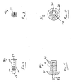
Figs. 2 and 3 are side and end views, respectively, of the pierce pin shaft preferably employed in the automatic inflator of the invention; -
Figs. 4 and 5 are side and end views, respectively, of the pierce pin preferably employed in the automatic inflator of the invention; -
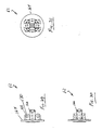
Figs. 6, 7, 8 and 9 are side, end views, respectively, and a diametrical cross-sectional view of the cylinder adaptor of the cylinder indicator preferably employed in the automatic inflator of the invention; -
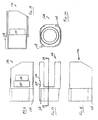
Figs. 10, 11 and 12 are side views and an end view, respectively, of the reciprocating member of the cylinder indicator preferably employed in the automatic inflator of the invention; -
Figs. 13, 14 and 15 are end, side and diametrical cross-sectional views, respectively, of the cylinder adaptor of the threaded cap preferably employed in the automatic inflator of the invention; -
Figs. 16, 17, 18, 19 and 20 are side views, a diametrical cross-sectional view and an end view, respectively, of the sleeve of the cap indicator preferably employed in the automatic inflator of the invention; -
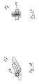
Figs. 21 and 22 are side and end views, respectively, of the actuator pin of the water-activated actuator assembly preferably employed in the automatic inflator of the invention; -
Fig. 23 is a diametrical cross-sectional view of a bobbin of the water-activated actuator assembly preferably employed in the automatic inflator of the invention; -
Figs. 24, 25 and 26 are end, side and diametrical cross-sectional views, respectively, of the plug of the bobbin indicator preferably employed in the automatic inflator of the invention; -
Figs. 27 and 28 are side and end views, respectively, of the transfer lever preferably employed in the automatic inflator of the invention; -
Figs. 29, 30 and 31 are side and end views, respectively, of the exhaust manifold preferably employed in the automatic inflator of the invention; -
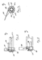
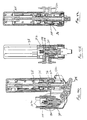
Figs. 32, 33 and 34 are cross-sectional views of the automatic inflator of the invention in a fully armed condition; -
Figs. 35, 36 and37 are cross-sectional views of the automatic inflator of the invention in a fired, inoperable condition; -
Figs. 38 and 39 are cross-sectional views of the automatic inflator of the invention in a cap-off, inoperable condition; -
Figs. 40 ,41 ,41A and 42 are cross-sectional views of the automatic inflator of the invention in a fired, cylinder-off, inoperable condition; - Similar reference numerals refer to similar parts throughout the several figures.
- Referring to
Fig. 1 , theautomatic inflator 10 of the invention comprises a generally rectangularhollow body 12 with aboss 14 containing apierce pin assembly 16 for receiving agas cylinder 18 and atubular portion 20 containing an water-activatedactuator assembly 22 that forcibly actuates thepiece pin assembly 16 by means of an internalpivotal transfer lever 24 upon submersion in water. Theinternal transfer lever 24 is provided with a tab or ball lanyard 24L for manual actuation. - An
indicator window 26 is positioned through theside wall 28 of theinflator body 12 to indicate the firing condition of theinflator 10. Specifically, theinflator 12 includes agas cylinder indicator 30 that indicates via theindicator window 26 whether a chargedgas cylinder 18 is connected to theboss 14 of the inflator 10, abobbin indicator 32 that indicates via theindicator window 26 whether anoperable bobbin 34 is installed in the water-activatedactuator assembly 22, and acap indicator 36 that indicates via theindicator window 26 whether the threadedcap 38 is fully installed onto thetubular portion 20. - The
gas cylinder indicator 30 includes acylinder adaptor 40 that is threaded onto theneck 42 of thegas cylinder 18. Thecylinder adaptor 40 cooperates with theother cylinder indicator 30 components within theboss 14 of the inflator 10 to not only provide the cylinder status via theindicator window 26 but also prevents, through the use of afracturable collar 44 that is fractured upon firing, a spentgas cylinder 18 from being reinstalled onto theboss 14 of theinflator 10. - For clarity in understanding the structure and operation of the inflator 10, the various components of the inflator 10 are first described separately and then the positions of the various indicators are described in relation to the inflator's fully-operational condition and then in its "fired" condition. The positions of the indicators are then described for cylinder-removed and cap-off inoperable conditions.
- The pierce pin shaft 46 includes a generally elongated configuration that is reciprocatingly positioned within the longitudinal bore 48 of the
boss 14. The pierce pin shaft 46 includes an increased diameter portion 50 and a reduceddiameter portion 52. A dome-shapedhead 54 is formed at the end of the increased diameter portion 50. A pair of O-ring slots 56 are formed at the other end of the increased diameter portion 50 for receiving conventional O-rings 58. The spacings between the O-rings slots 56 and hence the O-rings 58, is sufficient to span an exhaust hole 60 formed through thewall 62 of theboss 14 leading from the longitudinal bore 48 to anexhaust manifold 62. In this manner, with the pierce pin shaft 46 fully forwardly positioned within the longitudinal bore 48 after removal of the gas cylinder 18 (seeFig. 41 ), the O-rings 58 straddle the exhaust hole 60 thereby preventing leakage of gas from the inflated article through the exhaust hole 60 and longitudinal bore 48 to the atmosphere. - The reduced-
diameter portion 52 of the pierce pin shaft 46 includes an axialblind hole 64 for receiving a pierce pin 66. - The pierce pin 66 comprises a generally cylindrical base portion 68, a dome-shaped
head portion 70 and asharp piercing tip 72. The pierce pin 66 is preferably composed of a metal of sufficient hardness such that the piercingtip 72 is capable of piercing the frangible seal of thegas cylinder 18. The base portion 68 includes a plurality of annular ridges 74 having sharp edges formed in the direction of the piercingtip 72. The outer diameter of the annular ridges 74 is dimensioned to be permanently staked into theblind hole 64 of the pierce pin shaft 46. Alongitudinal slot 76 is formed along the length of thepierce pin tip 72 andhead portion 70 to allow, upon firing, the flow of gas from thegas cylinder 18 through the pierce pin 66 and then past the reduceddiameter portion 52 of the pierce pin shaft 46 into the exhaust hole 60 andmanifold 62 to inflate the inflatable article (seeFig. 36 ). - The
cylinder adapter 40 is one component of thegas cylinder indicator 30 that cooperates with the other component (the reciprocating member) of thegas cylinder indicator 30 inside theboss 14 of theinflator 10. Thecylinder adapter 40 comprises a generallycylindrical base portion 78 having alongitudinal bore 80 with internal threads 82 for threadably receiving the threaded neck of thegas cylinder 18 and sealing it into position by means of an O-ring 84. Preferably an adhesive is used for a permanent, non-removable threaded connection. Thebase portion 78 includes anannular slot 86 for receiving an O-ring 88 for sealing thebase portion 78 within the longitudinal bore 48 of theboss 14 of the inflator 10 when inserted therein. - The
cylinder adapter 40 includes a pair of bayonet lugs 90 formed diametrically on opposing outer surfaces of itsbase portion 78. The bayonet lugs 90 are dimensioned and configured for insertion withincomplementary bayonet slots 92 formed in thewall 62 of the longitudinal bore 48 of theboss 14 of the inflator 10 through a conventional push, twist and lock bayonet movement thereby allowing thecylinder adapter 40 and thegas cylinder 18 threaded thereto to be conveniently bayonet-coupled axially to theboss 18 of theinflator 10. - The end of the
cylinder adapter 40 comprises anannular fractuable collar 44 which is connected to thebase portion 78 by means of a plurality of radialfracturable webs 94. The size and thickness of thewebs 94 are designed to have sufficient strength to push the spring-loaded components of thecylinder indicator 30 inwardly inside theboss 14 as thecylinder adapter 40 is bayonet-coupled to the boss of theboss 14 yet of sufficient weakness to be forcibly fractured by the components of the cylinder indicator 30 (i.e., thearms 102 of the reciprocatingmember 96 described below) that extend from theboss 18 upon firing of theinflator 10. - Without departing from the spirit and scope of the invention, in lieu of the
webs 94, thefracturable collar 44 may comprise an annular collar with fracturable segments that are fractured by thearms 102 of the reciprocatingmember 96 upon firing of the inflator. Alternatively, in lieu of thewebs 94, thefracturable collar 44 may comprise a configuration that snap fits into thebase portion 78 and that can be releasably fractured or snapped apart upon firing. - As noted above, the
cylinder adapter 40 is one component of thegas cylinder indicator 30 that cooperates with the other component (the reciprocating member 96) of thegas cylinder indicator 30 inside theboss 14 of theinflator 10. The reciprocatingmember 96 comprises adome portion 98 having anindicator shutter 100 extending tangentially therefrom and a plurality of upstanding arms 102 (e.g., four) extending parallel to the axis of thedome portion 98. The length and width of theindicator shutter 100 is sufficient to extend from thedome portion 98 acrossbody 12 to theindicator window 26 so as to be visible thereto when aligned therewith. Theshutter 100 is formed tangentially relative to thedome portion 98 so as to provide sufficient room inside thebody 12 for the transfer lever 102 (described below) to fully operate. Thedome portion 98 may further comprise aslot 99 for additional clearance. - The
upstanding arms 102 of the reciprocatingmember 96 are of sufficient length to extend throughcorresponding holes 104 formed in thewall 62 of theboss 14 of theinflator body 12 and engage thefracturable collar 44 of thecylinder adapter 40 as described above. - The reciprocating
member 96 also comprises a blockingarm 106 extending axially from thedome portion 98 parallel to theupstanding arms 102 for reciprocating passage through ahole 108 formed in thewall 62 of theboss 14 in alignment with one of thebayonet slots 92. The length of the blockingarm 106 relative to the length of theupstanding arms 102 is such that it enters thebayonet slot 92 and blocks thebayonet lug 90 of thecylinder adapter 40 from being bayonet-coupled to theboss 14 of the inflator 10 if thefracturable collar 44 of thecylinder adapter 40 has been fractured (seeFig. 41 ). - If the
fracturable collar 44 of thecylinder adapter 40 has not been fractured, thecollar 44 forces the reciprocatingmember 96 via theupstanding arms 102 to a position fully retracted within theboss 14 andbody 12. Simultaneously, the blockingarm 106 is retracted to a non-blocking position allowing thecylinder adapter 40 to be bayonet-coupled to theinflator 10. - The
dome portion 98 comprises anaxial hole 110 of a diameter to loosely receive the pierce pin shaft 46 with thehead 54 thereof being seated on the surface of thedome portion 98. In this manner, once the inflator 10 is fired upon immersion in water and thetransfer lever 24 is forcibly pivoted thereby to engage thehead 54 of the pierce pin shaft 46, the reciprocatingmember 96 is likewise forcibly moved from its retracted position within theboss 14 to the extended position with theupstanding arms 102 being forcibly moved out of theboss 14 into engagement with thecollar 44. Thus, while moving to the extended position, theupstanding arms 102 forcibly fractures thecollar 44 of thecylinder adapter 40 and, simultaneously, theindicator shutter 100 moves into alignment with theindicator window 26. With the reciprocatingmember 96 being colored "red", it is readily seen that upon firing of the inflator 10, thered indicator shutter 100, being now visible through theindicator window 26, visually indicates an inoperable condition. Further, the redupstanding arms 102 extending from the end of theboss 14 and the blockingarm 106 being visible in thebayonet slot 92 likewise indicate an inoperable condition. - The threaded
cap 38 of the inflator 10 includes a generally elongated configuration withinternal threads 112 for threaded engagement with the external threads 114 of thetubular portion 20 of theinflator body 12. Positioned axially within thecap 38 and extending from the bottom wall 116 thereof, is anelongated retainer 118 for removably receiving the actuator pin 120 (see below) therein and allowing it to slide axially within theretainer 118 by a distance substantially equal to the length of theretainer 118. The outer surface of thecap 38 may includelongitudinal recesses 122 to assist in the grasping of thecap 38 during assembly. - Importantly, the cap includes 38 opposing flood holes 124 (see
Fig. 42 ), approximately midway along its length. Eachflood hole 124 allows water to flow therethrough into thebobbin 34 to dissolve the pill thereof immediately upon submersion of the inflator 10 in water. However, in order to minimize inadvertent actuation from splashing, it is noted that the length of thetubular portion 20 as well as thecap 38 is significant so as to produce a tube-in-tube configuration with the flood holes 124 being positioned approximately midway thereof. With the inflator 10 being stored in an upright position, it should be readily seen that inadvertent splashing may result in water entering the flood holes 124 but, due to the substantial length of thetubular portion 20, with itsuppermost end 20E extending substantially above the flood holes 124, would effectively preclude from such water reaching thebobbin 34 and causing premature actuation. - The
cap indicator 36 indicates when the threadedcap 38 has been fully threaded onto thetubular portion 20 of theinflator 10. Thecap indicator 36 comprises a spring-loaded tabbedaxial sleeve 126 concentrically positioned about the bobbin indicator plug 154 (see below) in axial alignment with thetubular portion 20. Thetabs 128 of thesleeve 126 extend through and protrude from corresponding slots 130 formed in the lowermost portion of thetubular portion 20. Thesleeve 126 is resiliently biased in the direction toward thetubular portion 20 by means of aspring 132 concentrically entrained between thesleeve 126 and thehead 156 of the plug 154 (seeFig. 37 ). - The
tabs 128 and slots 130 are in alignment with the threads 114 of thetubular portion 20 such that, as the threadedcap 38 is fully threaded onto the threads 114 of thetubular portion 20 to the point of bottoming-out, the protrudingtabs 128 are engaged by the lowermost edge of thecap 38 and thesleeve 126 is forced axially away from thetubular portion 20 against the force of thespring 132. As thesleeve 126 is forced away, awindow 134 formed in thesleeve 126 is moved into alignment with theindicator window 26 of theinflator body 12. - Thus, it should be appreciated that when the
cap 38 is not fully threaded onto thetubular portion 20, thesleeve 126 is moved outwardly by thespring 126 whereupon thered side 136 of thered sleeve 126 is visible through theindicator window 26 to indicate a non-operable condition. However, when thecap 38 is fully threaded onto thetubular portion 20, thewindow 134 becomes aligned with theindicator window 26 thereby no longer indicating a non-operable condition. - The
actuator pin 138 includes a generally elongated configuration having at its upper end aprotrusion 140 for snap-fitting into theretainer 118 formed in thecap 38. Theactuator pin 128 further includes astop flange 142 allowing a heavy-duty spring 144 to be captured between thestop flange 142 and the bottom wall 116 of thecap 38 as theactuator pin 138 is snap-fitted into theretainer 118. - The other end of the
actuator pin 138 comprises aseat portion 146 which is dimensioned and configured to seat within the seat of anoperable bobbin 34 in such a manner that as thecap 38 is threaded onto thetubular portion 20 with an operable 34 bobbin installed, theseat portion 146 engages thereagainst and the spring 144 captured between thestop flange 142 and the bottom wall 116 of thecap 38 is forcibly compressed. It is noted that when thebobbin 34 is submerged in water, it releases the now spring-loadedactuator pin 138 by unseating theseat portion 146 whereupon theactuator pin 138 forcibly moves inwardly to fire theactuator 10. - The
bobbin 34 comprises a cylindrical configuration containing a water-dissolvable ordestructible pill 148 that supports a plurality of arms 150 is a parallel position to define a seat 152 into which theseat portion 146 of theactuator pin 138 is seated and held-back against the force of the compression spring 144. Once thepill 148 is subjected to water as in the case of submerging the inflator 10, thepill 148 looses its ability to support the arms 150 to hold-back theactuator pin 138 and thepin 138 forcibly moves forward to strike thebobbin indicator plug 154. A more complete description of thebobbin 34 and animproved pill 148 is set forth in the patent application, the disclosure of which is hereby incorporated by reference herein, entitled "Bobbin for Automatic Inflators" filed concurrently herewith by the same inventors of this application. - The
bobbin indicator 32 comprises anelongated plug 154 having ahead 156 reciprocally positioned in theinflator body 12 in alignment with theactuator pin 138 of the water-activatedactuator assembly 22 in thetubular portion 20. Theplug 154 is biased away from the elongated by means of thespring 132 being entrained between thesleeve 126 and thehead 154 of theplug 154. - The
head 156 of theplug 154 is preferably colored "green". The length of theplug 154 is such that when the spring-loadedactuator pin 138 is being held back into its cocked position by thebobbin 34, thegreen head 156 of the plug is in alignment with theindicator window 26, thereby representing an operable firing condition for thebobbin 34. - Conversely, upon firing of the inflator 10, the spring-loaded
actuator pin 138 is released by thebobbin 34 and engages theplug 154 to force it axially within thebody 12 to a position where thegreen head 156 thereof is no longer in view within theindicator window 26, thereby no longer indicating an operable position of theinflator 10. - Through a seesaw action, the
transfer lever 24 functions to transfer axial movement, of thebobbin indicator plug 154 upon firing to the pierce pin shaft 46 to force the pierce pin 66 outwardly through the frangible seal of thegas cylinder 18 and cause firing of the same. More particularly, thetransfer lever 24 comprises a pivot hole 158 for receiving apivot pin 160 inserted through correspondingholes 162 formed in the opposingside walls 28 of theinflator body 12. Adust cap 162 may be secured by thepivot pin 160 about the opened end of theinflator body 12. Thetransfer lever 24 may be provided with a tab or ball lanyard 163 for manual inflation. - The
improved exhaust manifold 62 of the invention comprises a generally disk-shape configuration 164 having a protruding hollowtubular portion 166 dimensioned to sealingly engage into the exhaust hole 60 of theboss 14 of theinflator body 12. In this regard, thetubular portion 166 and correspondingly, the exhaust hole 60, may comprise complementary stepped configurations of increased and decreased diameters allowing an O-ring 166 to be positioned on the reduced diameter portion of thetubular portion 166 for sealing engagement with the reduced diameter portion of the exhaust hole 60 when the manifold 62 is mounted to theinflator body 10. - The mount may comprise of opposing
ears 168 on the disk-shapedportion 164 of theexhaust manifold 62 that mate with complementary opposing ears 169 (or complementary opposing pairs ofears 169 as shown) formed on the exterior of theboss 14 of theinflator body 12. Theears holes 170 for receiving respective coupling pins or, as shown, aU-shaped coupling pin 172. - Importantly, the
improved exhaust manifold 62 of the invention eliminates the need for the in situ molding of a metal schraeder valve assembly with the disk-shaped portion as typified by the prior art inflators. However, as in the case of the prior art, the disk-shaped portion may be easily sealingly connected to the article to be inflated. - When the
automatic inflator 10 of the invention is fully operable with a chargedgas cylinder 18 installed, with thecap 38 fully threaded into position and with anoperable bobbin 34 installed, thegas cylinder indicator 30 is not indicating an inoperable condition because its reciprocatingmember 96 is fully retracted by means of thecollar 44 of itscylinder adaptor 40 such that thered indicator shutter 100 is out of view of theindicator window 26 nor is thecap indicator 36 is indicating an inoperable condition because thewindow 134 of itssleeve 126 is aligned with theindicator window 26. Yet, thebobbin indicator 34 is indicating an operable condition because thegreen head 156 of itsplug 154 is visible through theindicator window 26. - When the
automatic inflator 10 of the invention has been fired due to the failure of thebobbin 34, the lack of abobbin 34 being installed or the manual firing (via the lanyard 24L) or automatic firing (upon submersion in water), thegas cylinder indicator 30 immediately indicates an inoperable condition because its reciprocatingmember 96 is fully extended such that thered indicator shutter 100 is in view of theindicator window 26. As theindicator shutter 100 constitutes the first layer visible through theindicator window 26, it takes priority to indicate an inoperable condition irrespective of the operational status of thecap indicator 36 indicating thecap 38 condition and irrespective of thebobbin indicator 32 indicating thebobbin 34 condition. - When the
cap 38 is at least partially unthreaded, thecap indicator 36 indicates an inoperable condition because thered side 136 of itssleeve 126 comes into view in theindicator window 26. As thesleeve 126 constitutes the second layer visible through theindicator window 26, it takes priority over thebobbin indicator 32 to indicate an inoperable condition due to the loosedcap 38 irrespective of the operational status of thebobbin indicator 32 indicating thebobbin 34 condition. - When the
gas cylinder 18 is removed, thegas cylinder indicator 30 indicates an inoperable condition because its reciprocatingmember 96 is urged byspring 132 via thetransfer lever 24 to be fully extended whereupon thered indicator shutter 100 is in view of theindicator window 26. As noted above, because theindicator shutter 100 constitutes the first layer visible through theindicator window 26, it takes priority to indicate an inoperable cylinder-off condition irrespective of the operational status of thecap indicator 36 indicating thecap 38 condition and irrespective of thebobbin indicator 32 indicating thebobbin 34 condition. - An essential feature of the invention is the fact that the cylinder indicator, the cap indicator and the bobbin indicator are functionally intercoupled to represent their respective status conditions through the indicator window. Consequently, the automatic inflator of the invention achieves a "single-point" status indication of the complete operational status of the inflator as well as the gas cylinder.
Claims (16)
- An automatic inflator having a status indicator that indicates whether a fully-charged, unspent gas cylinder (18) has been installed to the automatic inflator, whether a fully-operable bobbin (34) has been properly installed within the automatic inflator and whether the threaded cap (38) of the automatic inflator has been fully installed, comprising an indicator window (26) that displays one color when the automatic inflator is fully operational automatically and another color when the automatic inflator is at least partially inoperable automatically due to the removal of the gas cylinder (18), due to at least partial removal of the threaded cap (38), or due to the firing of the inflator resulting in a spent bobbin (34) or gas cylinder (18), wherein the cylinder indicator, the cap indicator and the bobbin indicator are functionally intercoupled to represent their respective status conditions through the indicator window (26).
- An automatic inflator as set forth in claim 1, wherein said one color is green and said other color is red.
- An inflator as set forth in claim 1 wherein the status indicator that indicates whether a fully-charged, unspent gas cylinder (18) has been installed to said inflator, comprises in combination:a cylinder adapter (40) for mounting onto said neck of said gas cylinder (18), said cylinder adapter (40) comprising a tubular configuration having bayonet lugs (90) about an outer periphery and a fracturable collar (44) about an inner end;an inflator body (12) comprising a boss (14) with bayonet slots (92) for receiving said bayonet lugs (90) for coupling said cylinder adapter (40) to said inflator body (12);a reciprocating member (96) mounted in axial alignment with said boss (14) of said inflator body (12), said reciprocating member (96) including upstanding arms (102) that engage through corresponding holes (104) in a longitudinal wall of said boss (14) of said inflator body (12) and are (a) forcibly retracted within said boss (14) against a force of a spring by said fracturable collar (44) of said cylinder adapter (40) as said gas cylinder (18) is bayonet-installed into said boss (14) and (b), upon firing of said gas cylinder (18), forced outwardly from said boss (14) to forcibly fracture said collar (44) of said cylinder adapter (40).
- The inflator as set forth in Claim 3, wherein said reciprocating member (96) includes an upstanding blocking arm (106) that reciprocates within another hole (108) in said longitudinal wall (62) of said boss (14) to move into a blocking position within said bayonet slot when said reciprocating member (96) is forced forwardly upon firing thereby assuring that a spent said gas cylinder (18) with a fractured collar is not re-installed onto said inflator.
- The inflator as set forth in Claim 4, wherein said reciprocating member (96) comprises includes a sidewise projecting shutter (100) that moves from an obscured position across an indicator window (26) formed in said body as said reciprocating member (96) is forced forwardly upon firing.
- The inflator as set forth in Claim 5, wherein said shutter (100) is colored to provide a visual indication of a fired condition via said indicator window (26).
- The inflator as set forth in Claim 6, wherein said upstanding arms (102) and said upstanding blocking arm (106) are colored to provide a visual indication of when said upstanding arms (102) are in said extended position from said boss (14) and when said blocking arm (106) is blocking said bayonet slot.
- An automatic inflator as set forth in claim 1 comprising in combination:a bobbin indicator (32) that indicates whether a fully-operable bobbin (34) has been properly installed within said automatic inflator; anda cap indicator (36) that indicates whether a threaded cap (38) of said automatic inflator has been fully installed.
- The automatic inflator as set forth in Claim 8, wherein said bobbin indicator (32) comprises a bobbin indicator plug (154) with a colored head (156) that is viewable through an indicator window (26) of said inflator and wherein said cap indicator (36) indicates when a threaded cap (38) has been fully threaded onto a threaded tubular portion (20) of said inflator, said cap indicator (36) including an axial sleeve (126) with tabs extending through corresponding holes formed in a lowermost portion of said threaded tubular portion (20) such that as said threaded cap (38) is fully threaded onto said threaded tubular portion (20), said protruding tabs are forced longitudinally inwardly and a sleeve window (134) formed in said sleeve (126) is moved into alignment with said indicator window (26) of said inflator and when so aligned, said head (156) of said bobbin indicator plug (154) is viewable through said indicator window (26) and through said aligned sleeve window (134) whereas when said cap (38) is at least partially unthreaded, said window (134) of said sleeve (126) is no longer in alignment and a side wall of said sleeve (126) appears in said indicator window (26), thereby indicating an inoperable said inflator when said cap (38) is not fully installed.
- An automatic inflator as set forth in claim 1 comprising a single point indicator having an indicator window (26) that displays one color when said automatic inflator is fully operational and a different color when said automatic inflator is at least partially inoperable due to a removal of a gas cylinder (18), due to at least partial removal of a threaded cap (38), or due to a firing of said inflator resulting in a spent bobbin (34) or gas cylinder (18).
- An automatic inflator as set forth in claim 1 having an elongated threaded cap (38) that threadably engages an elongated tubular portion (20) of an actuator body to achieve a tube-in-tube arrangement that minimizes inadvertent actuation of said automatic actuator when exposed to wet conditions such as water splashes.
- An automatic inflator as set forth in claim 1 comprising an inflator exhaust manifold (26) for connecting the automatic inflator to an article to be inflated, said exhaust manifold (26) comprising a generally disk-shape portion (164) having a protruding hollow tubular portion (166) dimensioned to sealingly engage into an exhaust hole (60) of said inflator, at least one ear (168) that mate with at least one complementary opposing ear (169) formed on an exterior of said inflator body (12), said mating said ears each having at least one aligned hole (170) for receiving a pin (66,172).
- An automatic inflator as set forth in Claim 12, where the exhaust manifold (26) comprises a tubular portion (166) further comprising stepped configurations of an increased diameter portion and a decreased diameter portion and an O-ring (166) positioned on said reduced diameter portion for sealing engagement with complementary reduced diameter portion of said exhaust hole (60) of said inflator when said exhaust manifold (26) is mounted therein.
- An automatic inflator as set forth in claim 1 comprising a cap indicator (36) for indicating when a threaded cap (38) has been fully threaded onto a threaded tubular portion (20) of said inflator, said cap indicator (36) including an axial sleeve (126) with tabs (128) extending through corresponding holes (130) formed in a lowermost portion of said threaded tubular portion (20) such that as said threaded cap (38) is fully threaded onto said threaded tubular portion (20), said protruding tabs (128) are forced longitudinally inwardly to visually indicate when said threaded cap (38) is fully threaded onto said threaded tubular portion (20).
- A method for indicating the operating condition of an automatic inflator having a gas cylinder (18), a cap (38) and a bobbin assembly (22), comprising the steps of:if said gas cylinder (18) is missing or if a discharged gas cylinder (18) is installed, displaying an indicator (100) to indicate an inoperable condition of said inflator;if said cap (38) is not fully threaded into position, displaying another indicator (36) to indicate an inoperable condition of said inflator; andallowing visualization of at least a portion (156) of said bobbin assembly (22) only if said bobbin assembly is operational, wherein the cylinder indicator, the cap indicator and the bobbin indicator are functionally intercoupled to represent their respective status conditions through an indicator window (26).
- A method as set forth in claim 15 wherein said steps comprise:if said gas cylinder (18) is missing or if a discharged gas cylinder (18) is installed, displaying a red indicator shutter (100) via the indicator window (26);irrespective of whether said red indicator shutter (100) is moved out from view of said indicator window (26) indicating that a charged gas cylinder (18) is installed, displaying a red colored side of a sleeve (126) in view in said indicator window (26) to indicate an inoperable condition if said cap (38) is not fully threaded into position;if said red indicator shutter (100) is moved out from view of said indicator window (26) indicating that a charged gas cylinder (18) is installed, if said cap (38) is fully threaded into position and if an operable said bobbin assembly (22) is installed to hold-back an actuator pin (120,138) in a cocked position, aligning a sleeve window (134) of said sleeve (126) with said indicator window (26) allowing visualization of at least a portion (156) of said bobbin assembly (22); andupon firing of said inflator, said actuator pin (120,138) forces said bobbin indicator (32) pin inwardly to move a transfer lever (24,102) which then forces said reciprocating member (96) and its arms (102) forwardly whereupon said red indicator shutter (100) moves into view in said indicator window (26) to indicate an inoperable condition of said inflator.
Applications Claiming Priority (3)
| Application Number | Priority Date | Filing Date | Title |
|---|---|---|---|
| US948533 | 2001-09-07 | ||
| US09/948,533 US6589087B2 (en) | 2001-09-07 | 2001-09-07 | Automatic inflator with status indicator |
| PCT/US2002/028032 WO2003022631A2 (en) | 2001-09-07 | 2002-09-04 | Automatic inflator with status indicator |
Publications (3)
| Publication Number | Publication Date |
|---|---|
| EP1432610A2 EP1432610A2 (en) | 2004-06-30 |
| EP1432610A4 EP1432610A4 (en) | 2010-11-24 |
| EP1432610B1 true EP1432610B1 (en) | 2014-09-03 |
Family
ID=25487966
Family Applications (1)
| Application Number | Title | Priority Date | Filing Date |
|---|---|---|---|
| EP02798107.5A Expired - Lifetime EP1432610B1 (en) | 2001-09-07 | 2002-09-04 | Automatic inflator with status indicator |
Country Status (8)
| Country | Link |
|---|---|
| US (1) | US6589087B2 (en) |
| EP (1) | EP1432610B1 (en) |
| AU (1) | AU2009200406B2 (en) |
| DE (1) | DE02798107T1 (en) |
| DK (1) | DK1432610T3 (en) |
| ES (1) | ES2285968T3 (en) |
| NZ (1) | NZ531984A (en) |
| WO (1) | WO2003022631A2 (en) |
Families Citing this family (44)
| Publication number | Priority date | Publication date | Assignee | Title |
|---|---|---|---|---|
| DE10355794A1 (en) * | 2003-11-28 | 2005-06-16 | Robert Bosch Gmbh | Coordination of a vehicle stabilization system with an external vehicle dynamics control system |
| CA2565100A1 (en) * | 2004-04-29 | 2005-11-10 | Irvin Aerospace Canada Limited | Water activated inflator for inflatable device and method of air deployment |
| US7819714B2 (en) * | 2004-04-29 | 2010-10-26 | Irvin Aerospace Canada Limited | Water activated inflator for inflatable device and method of air deployment |
| US7128629B2 (en) * | 2004-08-26 | 2006-10-31 | Summers Michael S | Throwable emergency response automatic inflatable personal flotation device |
| US7004807B1 (en) | 2004-08-26 | 2006-02-28 | Summers Michael S | Throwable emergency response automatic inflatable personal flotation device |
| US7357689B2 (en) | 2005-01-19 | 2008-04-15 | Campbell Richard A | Automatic inflation device having a moisture activated trigger and release system with reduced force applied to the degradable element |
| US7445132B1 (en) * | 2005-08-24 | 2008-11-04 | The United States Of America As Represented By The Secretary Of The Navy | System for determining gas cartridge actuation state |
| US7475711B2 (en) * | 2006-05-16 | 2009-01-13 | Halkey-Roberts Corporation | Heat sealable inflator |
| US7854347B2 (en) * | 2006-06-02 | 2010-12-21 | Hudson Wang | Manual gas inflator |
| US7980799B1 (en) * | 2008-05-28 | 2011-07-19 | Rioux Paul A | Air bag inflator |
| US8360276B2 (en) * | 2009-04-15 | 2013-01-29 | Halkey-Roberts Corporation | Manual inflator with cylinder connector and status indicator |
| US8353736B2 (en) * | 2010-07-30 | 2013-01-15 | Hudson Wang | Double point indicating auto/manual gas inflator |
| DE102010046058B4 (en) * | 2010-09-22 | 2015-01-08 | Heraeus Medical Gmbh | Discharge device for expressing a content of a container and method for activating the discharge device |
| GB2485368B (en) * | 2010-11-11 | 2013-07-24 | United Moulders Ltd | Inflation device having a non-releasable casing located over a fluid container |
| JP5944684B2 (en) * | 2012-02-15 | 2016-07-05 | 日本炭酸瓦斯株式会社 | Body case and adapter attachment / detachment mechanism |
| US9365270B2 (en) * | 2014-02-11 | 2016-06-14 | William Lee | Inflator |
| WO2016154324A1 (en) * | 2015-03-23 | 2016-09-29 | Halkey-Roberts Corporation | Indicator for manual inflator |
| CN105620692A (en) * | 2015-07-06 | 2016-06-01 | 吴方春 | Portable inflatable lifesaving and floating-assisting device |
| US10039359B2 (en) * | 2016-06-28 | 2018-08-07 | Jack Barron | Catastrophic event responsive travel case with flotation and alerting |
| US10441761B2 (en) | 2016-07-01 | 2019-10-15 | Boston Scientific Scimed, Inc. | Delivery devices and methods |
| EP3568179B1 (en) | 2017-01-10 | 2021-10-27 | Boston Scientific Scimed, Inc. | Apparatuses for delivering powdered agents |
| NO344080B1 (en) * | 2017-06-16 | 2019-09-02 | Safe Inflator | Connecting device for connecting a compressed gas cylinder to an inflatable device |
| CN121944198A (en) | 2018-01-12 | 2026-05-01 | 波士顿科学国际有限公司 | Powder for achieving hemostasis |
| US11766546B2 (en) | 2018-01-31 | 2023-09-26 | Boston Scientific Scimed, Inc. | Apparatuses and methods for delivering powdered agents |
| MX2020013706A (en) * | 2018-06-13 | 2021-06-08 | Halkey Roberts Corp | Disposable inflator. |
| US11180230B2 (en) * | 2018-06-13 | 2021-11-23 | Halkey-Roberts Corporation | Disposable Inflator |
| EP3833423B1 (en) | 2018-10-02 | 2025-04-30 | Boston Scientific Scimed, Inc. | Devices for fluidization and delivering a powdered agent |
| KR20250092279A (en) | 2018-10-02 | 2025-06-23 | 보스톤 싸이엔티픽 싸이메드 인코포레이티드 | Devices for fluidization and delivering a powdered agent |
| NO345700B1 (en) * | 2018-12-14 | 2021-06-21 | Safe Inflator As | Connecting device for connecting a compressed gas cylinder to an inflatable device |
| MX2021009409A (en) | 2019-02-06 | 2021-12-10 | Boost Ideas Llc | WATER SAFETY ITEM OF CLOTHING, APPLIANCE AND RELATED METHODS. |
| FR3103085B1 (en) * | 2019-11-15 | 2022-03-25 | Livbag Sas | Personal inflatable safety device interface device |
| US11931003B2 (en) | 2019-12-03 | 2024-03-19 | Boston Scientific Scimed, Inc. | Medical devices for agent delivery and related methods of use |
| EP4545121A3 (en) | 2019-12-03 | 2025-07-16 | Boston Scientific Scimed, Inc. | Devices for delivering powdered agents |
| CN121512581A (en) | 2019-12-03 | 2026-02-13 | 波士顿科学国际有限公司 | Medical devices for drug delivery and related usage methods |
| EP4578478A3 (en) | 2019-12-03 | 2025-12-31 | Boston Scientific Scimed Inc. | MEDICAL DEVICE FOR ADMINISTERING A REMEDY |
| CN114845644B (en) | 2019-12-20 | 2026-03-06 | 波士顿科学国际有限公司 | Pharmaceutical delivery device |
| EP4041094A1 (en) | 2020-01-06 | 2022-08-17 | Boston Scientific Scimed, Inc. | Agent delivery systems |
| CN119971275A (en) | 2020-01-06 | 2025-05-13 | 波士顿科学国际有限公司 | Device for delivering powdered medicine |
| US12083216B2 (en) | 2020-02-18 | 2024-09-10 | Boston Scientific Scimed, Inc. | Hemostatic compositions and related methods |
| CN115243624A (en) | 2020-03-06 | 2022-10-25 | 波士顿科学国际有限公司 | Device for delivering powdered medicament |
| CA3175862A1 (en) | 2020-03-24 | 2021-09-30 | Boston Scientific Scimed, Inc. | Agent delivery systems and methods of using the same |
| CN121081715A (en) | 2020-04-17 | 2025-12-09 | 波士顿科学国际有限公司 | Hemostatic compositions and related methods |
| CN116171177A (en) | 2020-08-19 | 2023-05-26 | 波士顿科学国际有限公司 | Conveying device and using method thereof |
| WO2024015888A1 (en) | 2022-07-14 | 2024-01-18 | Boston Scientific Scimed, Inc. | Valve assembly for a device for delivering agents |
Family Cites Families (40)
| Publication number | Priority date | Publication date | Assignee | Title |
|---|---|---|---|---|
| US3059814A (en) | 1959-11-09 | 1962-10-23 | Eugene E Poncel | Actuator for emergency water equipment |
| US3091782A (en) | 1962-06-11 | 1963-06-04 | Aerotec Ind Inc | Apparatus for flotation of articles on water |
| US3426942A (en) | 1967-07-31 | 1969-02-11 | Jay El Products Inc | Water-responsive energizing apparatus |
| US3579964A (en) | 1969-07-01 | 1971-05-25 | Us Navy | Squib-powered automatic inflation device |
| GB1360212A (en) | 1970-12-21 | 1974-07-17 | Martin J | Survival or like packs particularly suitable for airmen |
| US3702014A (en) | 1971-02-19 | 1972-11-07 | Us Navy | Squib ejected marker buoy |
| US3809288A (en) | 1973-03-26 | 1974-05-07 | G Mackal | Inflation manifold |
| US3997079A (en) | 1974-04-17 | 1976-12-14 | Wolfgang Niemann | Automatic inflating device for lifesaving devices |
| US3910457A (en) | 1974-05-06 | 1975-10-07 | Koch & Sons Inc H | Electronic water-activated parachute release and life vest inflator |
| NL7710240A (en) | 1977-09-19 | 1979-03-21 | Patent Concern Nv | MOWING MACHINE. |
| US4223805A (en) | 1978-08-04 | 1980-09-23 | Mackal Glenn H | Automatic inflator |
| US4267944A (en) | 1978-08-07 | 1981-05-19 | Mackal Glenn H | Automatic inflator |
| US4260075A (en) | 1978-08-01 | 1981-04-07 | Mackal Glenn H | Automatic inflator |
| US4382231A (en) | 1980-11-17 | 1983-05-03 | Conax Corporation | Fluid conductivity sensor |
| US4513248A (en) | 1980-11-17 | 1985-04-23 | Conax Corporation | Fluid conductivity sensor |
| US4436159A (en) | 1981-05-01 | 1984-03-13 | Kidde, Inc. | Manual/electric activated squib actuated discharge valve for fire extinguishers |
| US4500014A (en) * | 1982-12-14 | 1985-02-19 | Halkey-Roberts Corp. | Multiple firing inflator |
| US4627823A (en) | 1984-07-23 | 1986-12-09 | Glenn Mackal | Safety latched automatic actuator and throwable personal flotation assembly |
| EP0241452B1 (en) * | 1984-10-29 | 1992-05-13 | HIERAT, Alexander | Additional device for inflatable gas balloon |
| US4708370A (en) * | 1985-11-14 | 1987-11-24 | Toddco | Recreational vehicle discharge pipe coupler |
| US4688833A (en) * | 1985-11-14 | 1987-08-25 | Toddco | Recreational vehicle discharge pipe adapter |
| US4927057A (en) * | 1989-05-30 | 1990-05-22 | Inflation Technologies & Innovation | Automatic inflator for inflatable articles |
| US5035345A (en) * | 1990-05-07 | 1991-07-30 | Apoc, Inc. | Automatic inflator for inflatable articles |
| US4972971A (en) * | 1989-06-29 | 1990-11-27 | Inflation Technologies & Innovation | Automatic inflator for inflatable articles |
| US5026310A (en) * | 1990-02-28 | 1991-06-25 | Halkey-Roberts Corporation | Electric autoinflator |
| US5076468A (en) | 1990-02-28 | 1991-12-31 | Halkey-Roberts Corporation | Squib inflator adaptor |
| US5098325A (en) * | 1990-06-04 | 1992-03-24 | Sunyong Kim | Personal, self-contained inflatable flotation apparatus |
| ATE118417T1 (en) | 1991-09-28 | 1995-03-15 | Bernhardt Apparatebau Gmbh Co | DEVICE FOR INFLATION, IN PARTICULAR A CONTAINER OR A FLOATING BODY OF A RESCUE APPARATUS. |
| DE9210848U1 (en) | 1992-08-13 | 1993-12-16 | Bernhardt Apparatebau Gmbh + Co., 22880 Wedel | Device for inflating, in particular a container or a float of a rescue device |
| DE9210849U1 (en) | 1992-08-13 | 1993-12-16 | Bernhardt Apparatebau GmbH & Co., 22880 Wedel | Display device for a device for inflating, in particular a container or a float of a rescue device |
| DE9303295U1 (en) | 1993-03-06 | 1994-07-07 | Bernhardt Apparatebau GmbH & Co., 22880 Wedel | Air cylinder indicator |
| DE9401917U1 (en) * | 1994-02-05 | 1994-03-31 | Bernhardt Apparatebau Gmbh + Co., 22880 Wedel | Trigger adapter for compressed gas cartridge |
| US5601124A (en) * | 1995-02-07 | 1997-02-11 | Halkey-Roberts Corporation | Autoinflator with apertured housing |
| US5694986A (en) | 1995-02-07 | 1997-12-09 | Halkey-Roberts Corporation | Automatic actuator with apertured housing and safety indicator |
| US5597091A (en) * | 1995-02-27 | 1997-01-28 | M.E.T.A. Reasearch Inc. | Safety indicator for an inflation system |
| US5775358A (en) | 1995-11-03 | 1998-07-07 | Halkey-Roberts Corporation | Indicator for compressed gas cartridge |
| US5852986A (en) * | 1996-02-05 | 1998-12-29 | Mackal; Glenn H. | Automatic inflator with status indicators |
| US5820431A (en) * | 1996-05-30 | 1998-10-13 | Biesecker Douglas A | Deployment mechanism for pocket-sized, emergency flotation device |
| US5643030A (en) | 1996-07-17 | 1997-07-01 | Brown; Dennis | Gas cartridge safety inflator apparatus |
| EP1036733B1 (en) * | 1999-03-13 | 2003-06-25 | Wolfgang Niemann | Automatic inflating arrangement for floatable life-saving device |
-
2001
- 2001-09-07 US US09/948,533 patent/US6589087B2/en not_active Expired - Lifetime
-
2002
- 2002-09-04 ES ES02798107.5T patent/ES2285968T3/en not_active Expired - Lifetime
- 2002-09-04 EP EP02798107.5A patent/EP1432610B1/en not_active Expired - Lifetime
- 2002-09-04 DE DE02798107T patent/DE02798107T1/en active Pending
- 2002-09-04 WO PCT/US2002/028032 patent/WO2003022631A2/en not_active Ceased
- 2002-09-04 NZ NZ531984A patent/NZ531984A/en not_active IP Right Cessation
- 2002-09-04 DK DK02798107.5T patent/DK1432610T3/en active
-
2009
- 2009-02-04 AU AU2009200406A patent/AU2009200406B2/en not_active Expired
Also Published As
| Publication number | Publication date |
|---|---|
| NZ531984A (en) | 2005-09-30 |
| ES2285968T3 (en) | 2015-01-20 |
| WO2003022631A2 (en) | 2003-03-20 |
| AU2009200406A1 (en) | 2009-02-26 |
| EP1432610A4 (en) | 2010-11-24 |
| DE02798107T1 (en) | 2006-10-12 |
| EP1432610A2 (en) | 2004-06-30 |
| WO2003022631A3 (en) | 2003-10-23 |
| US6589087B2 (en) | 2003-07-08 |
| US20030049981A1 (en) | 2003-03-13 |
| ES2285968T1 (en) | 2007-12-01 |
| AU2009200406B2 (en) | 2012-12-20 |
| DK1432610T3 (en) | 2014-12-01 |
Similar Documents
| Publication | Publication Date | Title |
|---|---|---|
| US6589087B2 (en) | Automatic inflator with status indicator | |
| US8360276B2 (en) | Manual inflator with cylinder connector and status indicator | |
| US5694986A (en) | Automatic actuator with apertured housing and safety indicator | |
| US5076468A (en) | Squib inflator adaptor | |
| US5601124A (en) | Autoinflator with apertured housing | |
| CA2980724C (en) | Indicator for manual inflator | |
| US8353736B2 (en) | Double point indicating auto/manual gas inflator | |
| US5026310A (en) | Electric autoinflator | |
| US6260570B1 (en) | Puncture disc raft inflation valve having a one-piece valve body | |
| EP2019779B1 (en) | Heat sealable inflator | |
| CA2017764A1 (en) | Inflation valve with actuating lever interlock | |
| WO2008047252A2 (en) | Manual gas inflator | |
| EP1425527B1 (en) | Bobbin for automatic inflator | |
| US5643030A (en) | Gas cartridge safety inflator apparatus | |
| US3802012A (en) | Fluid pressure sensing devices | |
| US5597091A (en) | Safety indicator for an inflation system | |
| AU2002341594A1 (en) | Bobbin for automatic inflator | |
| AU2012261490B2 (en) | Automatic inflator with status indicator | |
| AU2002332819A1 (en) | Automatic inflator with status indicator | |
| JP5833875B2 (en) | Inflating device firing pin | |
| HK1167375A (en) | Manual inflator with cylinder connector and status indicator | |
| HK1167375B (en) | Manual inflator with cylinder connector and status indicator | |
| JP2013078354A (en) | Inflator |
Legal Events
| Date | Code | Title | Description |
|---|---|---|---|
| PUAI | Public reference made under article 153(3) epc to a published international application that has entered the european phase |
Free format text: ORIGINAL CODE: 0009012 |
|
| 17P | Request for examination filed |
Effective date: 20040324 |
|
| AK | Designated contracting states |
Kind code of ref document: A2 Designated state(s): AT BE BG CH CY CZ DE DK EE ES FI FR GB GR IE IT LI LU MC NL PT SE SK TR |
|
| AX | Request for extension of the european patent |
Extension state: AL LT LV MK RO SI |
|
| DET | De: translation of patent claims | ||
| EL | Fr: translation of claims filed | ||
| A4 | Supplementary search report drawn up and despatched |
Effective date: 20101021 |
|
| 17Q | First examination report despatched |
Effective date: 20110519 |
|
| GRAP | Despatch of communication of intention to grant a patent |
Free format text: ORIGINAL CODE: EPIDOSNIGR1 |
|
| INTG | Intention to grant announced |
Effective date: 20140331 |
|
| GRAS | Grant fee paid |
Free format text: ORIGINAL CODE: EPIDOSNIGR3 |
|
| GRAA | (expected) grant |
Free format text: ORIGINAL CODE: 0009210 |
|
| AK | Designated contracting states |
Kind code of ref document: B1 Designated state(s): AT BE BG CH CY CZ DE DK EE ES FI FR GB GR IE IT LI LU MC NL PT SE SK TR |
|
| REG | Reference to a national code |
Ref country code: GB Ref legal event code: FG4D |
|
| REG | Reference to a national code |
Ref country code: CH Ref legal event code: EP Ref country code: AT Ref legal event code: REF Ref document number: 685433 Country of ref document: AT Kind code of ref document: T Effective date: 20140915 |
|
| RAP2 | Party data changed (patent owner data changed or rights of a patent transferred) |
Owner name: HALKEY-ROBERTS CORPORATION |
|
| REG | Reference to a national code |
Ref country code: IE Ref legal event code: FG4D |
|
| REG | Reference to a national code |
Ref country code: DE Ref legal event code: R096 Ref document number: 60246608 Country of ref document: DE Effective date: 20141016 |
|
| REG | Reference to a national code |
Ref country code: SE Ref legal event code: TRGR |
|
| REG | Reference to a national code |
Ref country code: CH Ref legal event code: NV Representative=s name: FIAMMENGHI-FIAMMENGHI, CH |
|
| REG | Reference to a national code |
Ref country code: DK Ref legal event code: T3 Effective date: 20141125 |
|
| REG | Reference to a national code |
Ref country code: NL Ref legal event code: T3 |
|
| REG | Reference to a national code |
Ref country code: EE Ref legal event code: FG4A Ref document number: E009905 Country of ref document: EE Effective date: 20141030 |
|
| REG | Reference to a national code |
Ref country code: ES Ref legal event code: FG2A Ref document number: 2285968 Country of ref document: ES Kind code of ref document: T3 Effective date: 20150120 |
|
| PG25 | Lapsed in a contracting state [announced via postgrant information from national office to epo] |
Ref country code: CY Free format text: LAPSE BECAUSE OF FAILURE TO SUBMIT A TRANSLATION OF THE DESCRIPTION OR TO PAY THE FEE WITHIN THE PRESCRIBED TIME-LIMIT Effective date: 20140903 |
|
| REG | Reference to a national code |
Ref country code: GR Ref legal event code: EP Ref document number: 20140402430 Country of ref document: GR Effective date: 20150128 |
|
| PG25 | Lapsed in a contracting state [announced via postgrant information from national office to epo] |
Ref country code: CZ Free format text: LAPSE BECAUSE OF FAILURE TO SUBMIT A TRANSLATION OF THE DESCRIPTION OR TO PAY THE FEE WITHIN THE PRESCRIBED TIME-LIMIT Effective date: 20140903 Ref country code: PT Free format text: LAPSE BECAUSE OF FAILURE TO SUBMIT A TRANSLATION OF THE DESCRIPTION OR TO PAY THE FEE WITHIN THE PRESCRIBED TIME-LIMIT Effective date: 20150105 Ref country code: SK Free format text: LAPSE BECAUSE OF FAILURE TO SUBMIT A TRANSLATION OF THE DESCRIPTION OR TO PAY THE FEE WITHIN THE PRESCRIBED TIME-LIMIT Effective date: 20140903 |
|
| REG | Reference to a national code |
Ref country code: DE Ref legal event code: R097 Ref document number: 60246608 Country of ref document: DE |
|
| PG25 | Lapsed in a contracting state [announced via postgrant information from national office to epo] |
Ref country code: MC Free format text: LAPSE BECAUSE OF FAILURE TO SUBMIT A TRANSLATION OF THE DESCRIPTION OR TO PAY THE FEE WITHIN THE PRESCRIBED TIME-LIMIT Effective date: 20140903 |
|
| PLBE | No opposition filed within time limit |
Free format text: ORIGINAL CODE: 0009261 |
|
| STAA | Information on the status of an ep patent application or granted ep patent |
Free format text: STATUS: NO OPPOSITION FILED WITHIN TIME LIMIT |
|
| 26N | No opposition filed |
Effective date: 20150604 |
|
| PG25 | Lapsed in a contracting state [announced via postgrant information from national office to epo] |
Ref country code: BG Free format text: LAPSE BECAUSE OF FAILURE TO SUBMIT A TRANSLATION OF THE DESCRIPTION OR TO PAY THE FEE WITHIN THE PRESCRIBED TIME-LIMIT Effective date: 20140903 |
|
| PG25 | Lapsed in a contracting state [announced via postgrant information from national office to epo] |
Ref country code: LU Free format text: LAPSE BECAUSE OF NON-PAYMENT OF DUE FEES Effective date: 20140904 Ref country code: TR Free format text: LAPSE BECAUSE OF FAILURE TO SUBMIT A TRANSLATION OF THE DESCRIPTION OR TO PAY THE FEE WITHIN THE PRESCRIBED TIME-LIMIT Effective date: 20140903 |
|
| REG | Reference to a national code |
Ref country code: FR Ref legal event code: PLFP Year of fee payment: 15 |
|
| REG | Reference to a national code |
Ref country code: FR Ref legal event code: PLFP Year of fee payment: 16 |
|
| REG | Reference to a national code |
Ref country code: FR Ref legal event code: PLFP Year of fee payment: 17 |
|
| PGFP | Annual fee paid to national office [announced via postgrant information from national office to epo] |
Ref country code: FR Payment date: 20210927 Year of fee payment: 20 Ref country code: FI Payment date: 20210929 Year of fee payment: 20 Ref country code: AT Payment date: 20210819 Year of fee payment: 20 Ref country code: EE Payment date: 20210818 Year of fee payment: 20 Ref country code: IT Payment date: 20210922 Year of fee payment: 20 Ref country code: IE Payment date: 20210927 Year of fee payment: 20 Ref country code: NL Payment date: 20210926 Year of fee payment: 20 |
|
| PGFP | Annual fee paid to national office [announced via postgrant information from national office to epo] |
Ref country code: GR Payment date: 20210929 Year of fee payment: 20 Ref country code: SE Payment date: 20210929 Year of fee payment: 20 Ref country code: BE Payment date: 20210927 Year of fee payment: 20 Ref country code: DE Payment date: 20210929 Year of fee payment: 20 Ref country code: GB Payment date: 20210927 Year of fee payment: 20 Ref country code: DK Payment date: 20210929 Year of fee payment: 20 |
|
| PGFP | Annual fee paid to national office [announced via postgrant information from national office to epo] |
Ref country code: ES Payment date: 20211001 Year of fee payment: 20 |
|
| PGFP | Annual fee paid to national office [announced via postgrant information from national office to epo] |
Ref country code: CH Payment date: 20211004 Year of fee payment: 20 |
|
| REG | Reference to a national code |
Ref country code: DE Ref legal event code: R071 Ref document number: 60246608 Country of ref document: DE |
|
| REG | Reference to a national code |
Ref country code: DK Ref legal event code: EUP Expiry date: 20220904 |
|
| REG | Reference to a national code |
Ref country code: NL Ref legal event code: MK Effective date: 20220903 |
|
| REG | Reference to a national code |
Ref country code: CH Ref legal event code: PL |
|
| REG | Reference to a national code |
Ref country code: ES Ref legal event code: FD2A Effective date: 20220927 |
|
| REG | Reference to a national code |
Ref country code: GB Ref legal event code: PE20 Expiry date: 20220903 |
|
| REG | Reference to a national code |
Ref country code: BE Ref legal event code: MK Effective date: 20220904 |
|
| REG | Reference to a national code |
Ref country code: FI Ref legal event code: MAE |
|
| REG | Reference to a national code |
Ref country code: AT Ref legal event code: MK07 Ref document number: 685433 Country of ref document: AT Kind code of ref document: T Effective date: 20220904 |
|
| REG | Reference to a national code |
Ref country code: IE Ref legal event code: MK9A |
|
| PG25 | Lapsed in a contracting state [announced via postgrant information from national office to epo] |
Ref country code: GB Free format text: LAPSE BECAUSE OF EXPIRATION OF PROTECTION Effective date: 20220903 Ref country code: ES Free format text: LAPSE BECAUSE OF EXPIRATION OF PROTECTION Effective date: 20220905 |
|
| PG25 | Lapsed in a contracting state [announced via postgrant information from national office to epo] |
Ref country code: IE Free format text: LAPSE BECAUSE OF EXPIRATION OF PROTECTION Effective date: 20220904 |