EP1432231A2 - Apparatus and method for noise free recording of high resolution, two dimensional images - Google Patents
Apparatus and method for noise free recording of high resolution, two dimensional images Download PDFInfo
- Publication number
- EP1432231A2 EP1432231A2 EP03028429A EP03028429A EP1432231A2 EP 1432231 A2 EP1432231 A2 EP 1432231A2 EP 03028429 A EP03028429 A EP 03028429A EP 03028429 A EP03028429 A EP 03028429A EP 1432231 A2 EP1432231 A2 EP 1432231A2
- Authority
- EP
- European Patent Office
- Prior art keywords
- scan
- pattern
- scanning
- positions
- minimum
- Prior art date
- Legal status (The legal status is an assumption and is not a legal conclusion. Google has not performed a legal analysis and makes no representation as to the accuracy of the status listed.)
- Withdrawn
Links
Images


Classifications
-
- H—ELECTRICITY
- H04—ELECTRIC COMMUNICATION TECHNIQUE
- H04N—PICTORIAL COMMUNICATION, e.g. TELEVISION
- H04N25/00—Circuitry of solid-state image sensors [SSIS]; Control thereof
- H04N25/48—Increasing resolution by shifting the sensor relative to the scene
Definitions
- the invention relates to a device for receiving high-resolution Two-dimensional images with moving image sensor and a method for Create optimized scan patterns for two-dimensional scanning Image recording systems, in particular for receiving finger, hand or Footprints or other geometrically highly accurate images to be evaluated which a movement can not be excluded.
- high-resolution image capture of objects e.g. Finger and Handprinting
- various recording methods can be used. So is for example, it is possible to use high-resolution image sensors to capture a single image of the image entire object to record.
- the rule still applies today that sufficiently high-resolution image sensors with appropriate parameters only at very high cost.
- a high-resolution Image also from several temporally successively and spatially offset recorded Images are composed at a lower resolution. It is the Image sensor moved between individual images to multiple images one after the other, which are then put together to form the result picture.
- the foregoing methods are scanning (i.e., by sensor motion scanning) recording method, since the camera image sensor for recording a entire picture is moved several times.
- the recording of high-resolution images with scanning recording method comes especially in the detection of stationary or little moving picture objects are used.
- the Microscan method was developed in order to achieve a high optical image resolution of the resulting image with available low-resolution camera sensors (with low pixel density).
- the main focus in performing the mechanical scanning of the Microscan method is to minimize the scan paths of the camera and thus minimize scan and image capture time.
- the camera is moved meandering during image acquisition starting at position 1 (see FIG. 2c for illustrating a 3 ⁇ 4 image scan).
- the Microscan method is used primarily in small objects with high resolution requirements and takes into account the fact that conventionally available image sensors (in particular CCD sensors) between the photosensitive image sensor elements have light-insensitive areas which serve to derive the signals of the sensor elements.
- the invention has for its object to provide a new way to accommodate high-resolution two-dimensional images with resolution-increasing Two-dimensional sensor movement to find the simple means a Significant reduction of image interference, which occurs during the movement of the object during the scan movement of the image sensor, reached.
- the object with a device for receiving high-resolution two-dimensional images in which for a resolution-increasing Multiplication of the scanned pixels, a scanning mechanism for two-dimensional Movement of the image sensor is present, solved by that at a selected scan grid with n scan positions in x-direction and m scan positions in y direction is a scan pattern for the sensor movement is present, in the form of Sample numbers has a fixed sequence of approached scan positions, wherein for locally adjacent scan positions in the x-direction and in the y-direction respectively a time interval, represented as the difference of the sample numbers, of at least two Scanning steps is available.
- the scan pattern for a given scan grid is optimized such that the time intervals between respectively locally adjacent scan positions in the x and y directions have a maximum and a minimum in the entire scan pattern that are as close as possible to each other.
- the scanning pattern characterized above is preferably used for image recorders with an nxm microscan. It can also be useful for a given nxm macroscan.
- the thus configured scan pattern is advantageously integrated into the drive software for the scanning mechanism of the image sensor.
- the selection of the appropriate scan pattern is preferably made by comparing the differences of maximum and minimum of each scan pattern, with the scan pattern having the smallest difference of maximum and minimum of the sample count differences being an optimum.
- Another convenient and more stringent criterion for selecting the appropriate scan pattern is by comparing the quotient of the minimum and maximum of each scan pattern by selecting the scan pattern having the largest minimum to maximum ratio of sample number differences as optimal.
- the inventive device consists of an image sensor by means of a scanning mechanism (not shown) in a predetermined scan grid 12 - as shown schematically in Fig. 1 as 3x4 scan grid - with a scan pattern 3, in which not the shortest displacement of the image sensor element 11, the target ,
- the scanning positions 14 are represented in the illustration of Fig. 1 by juxtaposed positions of a selected sensor element 11, wherein by sampling numbers 31, the consecutive numbering of the scan steps 13 over time is shown. It should be noted at this point that the juxtaposition of the scan positions 14 only serves the purpose of simplification and, in reality, a local overlap of the scan positions 14 is frequently provided.
- the suppression of artifacts 51 (only shown in FIG. 11) in result image 2 (see FIG. 2 b), which is shown in FIG.
- Fig. 2a is intended first to illustrate the conventional scanning principle of imagers with a macroscan.
- the aim of the macroscan is that the image section scanned by the image sensor 1 is shifted stepwise over a much larger image area of an object.
- By juxtaposing the scanned image excerpts of the size of the entire image sensor 1 with the edge length a produces the result image 2, which is composed in this case of a 2x2 macroscan.
- between the positions of the image sensor 1, which may also be different for the two dimensions of the image sensor 1, is in each case an edge length a of the image sensor 1 in a different direction.
- FIG. 2b shows the state of the art for image scanning by means of a 2x2 microscan.
- the image sensor 1 consists for example of 4x4 sensor elements 11 and is shifted by half the pixel pitch p / 2.
- the result image 2 which results from the so-called interleaving of the signals read out, exhibits a quadruple increase in pixel density and hence improved triggering as a result of the selected displacement path, which is shown as scan pattern 3 for the fourth sensor element 11 of the first line.
- FIG. 2 c again shows the same situation of FIG.
- the individual scanning steps 13 run in an ordered manner in the scanning grid 12, wherein the trajectory of the scanning steps 13 for clarifying the scanning pattern 3 has again been emphasized in addition to the scheme of the scan positions 14 approached one after the other whose temporal sequence is characterized by the scanning numbers 31.
- the designation (maximum, minimum) is used to classify the scanning patterns 3, the maximum 42 being the maximum temporal difference 32 and the minimum 41 being the minimum temporal difference 32 of all the scanning numbers 31 of spatially adjacent scanning positions 33 of a selected sensor element 11 and the minimum Differences 32 is used to classify the scanning patterns 3 into classes.
- the evaluation (11, 1) thus results - as can be easily read from FIG.
- Fig. 7 shows the list of scan pattern classes according to the above prescriptions of the 1st to 3rd steps of the algorithm for the 3x4 scan grid 12.
- the scan positions 33 of a selected sensor element 11 have been numbered from 1 to 12.
- a scanning pattern class 4 is to be identified by the minimum difference 32 of the scanning numbers 31 of adjacent scanning positions 33.
- the class 4 of scan patterns 3, which has the value one as the minimum 41 of the differences 32, is rejected immediately in the fourth step of the method, so that direct neighborhoods of the scan positions 33 (also in the transition to scan positions 34, cf. FIG. 9) are excluded ,
- This class 4 labeled (k, 1) includes six scan patterns 3.
- the scanning patterns (6, 2) and (8, 4) have the greatest proximity of the minimum and maximum of the sample number differences. If one now decides with a difference criterion between maximum and minimum, both scan patterns (6,2) and (8,4) are the same and can be selected as desired for the programming of the scanning mechanism of the image sensor 1.
- Fig. 8 shows the scanning pattern classes 4 for a 3x3 scan raster for the sake of explanation.
- the scan positions 33 according to FIG. 10 are in this case 1 to 9 numbered.
- As class division results from the permutations of Order of scan positions 33 only two classes 4 with four and two, respectively represented scan patterns 3, of which the first class (k, 1) by the above specified 4th procedural rule deleted.
- the remaining two scanning patterns 3 of the second class 4 with the marking (k, 2) have the classifications (8,2) and (7,2) and when using each of the selection steps 5.1 or 5.2, the Classification (7.2) as optimized scan pattern 43.
- FIG. 9 shows the scanning pattern 43 optimized according to the invention for a 3 ⁇ 4 scan grid 12 by identifying the scan positions 33 and 34 with sample numbers 31 and indicating differences 32 (as time intervals) of the locally adjacent scan positions 33 and 34.
- FIG. 9 is schematically applied in the same manner as FIG. 3 and embodies a representation equivalent to the scanning pattern 3 of FIG. 1 according to the invention.
- the significantly improved scanning quality of the scanning pattern 3 of FIG. 9 compared with FIG. 3 (prior art ffleander scan) can be seen in FIG. 11.
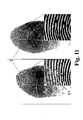
- FIG. 11 are the images of two images with a microscan in the 3x4 scan grid, in which the imaged finger has moved minimally, with the different scanning patterns 3 (according to FIGS. 3 and 9) have been detected.
- the left-hand image was taken with a meander-shaped scan [in the class diagram of FIG. 7: using the scan designation 3 with the class designation (11,1)] and shows clearly visible linear artifacts 51.
- the right-hand image was generated using the scan pattern 43 with classification (8,4) from Fig. 7 created. It can be seen that with the method according to the invention, the pronounced false line structures or linear artifacts 51 of the imaged fingerprint 5 do not occur any more (as in the left-hand illustration of FIG. 11) and the method thus has a significantly better behavior with respect to movements of the object shows.
- a significant improvement of image pickup devices that use a microscan to increase the resolution can be achieved with respect to susceptibility to image errors due to low object movement.
- the inventive method is with relatively little effort by Revision of the driver software of a scanning image sensor 1 and one-time Recalibration of image acquisition with this new software for all previously known optically scanning image sensor applicable.
- the application of the inventive method for generating a suitable scan pattern 3 are other than the above-mentioned scan grid 12 no limits, so that optimized for any two-dimensional scan mode Scan pattern 43 can be found as one stored in software Scan configuration determines the nature and quality of the image sensor.
Abstract
Description
Die Erfindung betrifft eine Einrichtung zur Aufnahme von hochaufgelösten zweidimensionalen Bildern mit bewegtem Bildsensor sowie ein Verfahren zum Erzeugen optimierter Scanmuster für zweidimensional scannende Bildaufnahmesysteme, insbesondere zur Aufnahme von Finger-, Hand- oder Fußabdrücken oder anderen geometrisch hochgenau auszuwertenden Bildern, bei denen eine Bewegung nicht ausgeschlossen werden kann.The invention relates to a device for receiving high-resolution Two-dimensional images with moving image sensor and a method for Create optimized scan patterns for two-dimensional scanning Image recording systems, in particular for receiving finger, hand or Footprints or other geometrically highly accurate images to be evaluated which a movement can not be excluded.
Für die hochaufgelöste Bildaufnahme von Objekten, wie z.B. Finger- und Handabdrücken, können verschiedene Aufnahmeverfahren eingesetzt werden. So ist es beispielsweise möglich, mit hochauflösenden Bildsensoren ein Einzelbild des gesamten Objektes aufzunehmen. Allerdings gilt dabei auch heute noch die Regel, dass hinreichend hochauflösende Bildsensoren mit entsprechenden Parametern nur zu sehr hohen Kosten verfügbar sind. Um das zu umgehen, kann ein hochaufgelöstes Bild auch aus mehreren zeitlich nacheinander und örtlich versetzt aufgenommenen Bildern mit geringerer Auflösung zusammengesetzt werden. Dabei wird der Bildsensor zwischen einzelnen Bildaufnahmen verschoben, um mehrere Bilder nacheinander aufzunehmen, die dann zum Ergebnisbild zusammengesetzt werden.For high-resolution image capture of objects, e.g. Finger and Handprinting, various recording methods can be used. So is For example, it is possible to use high-resolution image sensors to capture a single image of the image entire object to record. However, the rule still applies today that sufficiently high-resolution image sensors with appropriate parameters only at very high cost. To get around that, a high-resolution Image also from several temporally successively and spatially offset recorded Images are composed at a lower resolution. It is the Image sensor moved between individual images to multiple images one after the other, which are then put together to form the result picture.
Das Zusammensetzen der Einzelbilder ist auf zwei Arten möglich:
Die vorgenannten Verfahren sind scannende (d.h. durch Sensorbewegung abtastende) Aufnahmeverfahren, da der Kamera-Bildsensor für die Aufnahme eines kompletten Bildes mehrfach verschoben wird. Die Aufnahme hochaufgelöster Bilder mit scannenden Aufnahmeverfahren kommt vor allem bei der Erfassung von ruhenden oder wenig bewegten Bildobjekten zum Einsatz. The foregoing methods are scanning (i.e., by sensor motion scanning) recording method, since the camera image sensor for recording a entire picture is moved several times. The recording of high-resolution images with scanning recording method comes especially in the detection of stationary or little moving picture objects are used.
Das Microscan-Verfahren wurde entwickelt, um mit verfügbaren niedrig auflösenden
Kamerasensoren (mit geringer Pixeldichte) eine hohe optische Bildauflösung des
Ergebnisbildes zu erzielen. Das Hauptaugenmerk bei der Ausführung der
mechanischen Abtastbewegung des Microscan-Verfahrens ist auf eine Minimierung
der Abtastwege der Kamera und somit auf eine Minimierung der Scan- und der
Bildaufnahmezeit gerichtet. Dazu wird die Kamera bei der Bildaufnahme beginnend
bei Position 1 mäanderförmig bewegt (siehe Fig. 2c zur Veranschaulichung eines 3x4-Bildscans).
Das Microscan-Verfahren wird vor allem bei kleinen Objekten mit hohen Auflösungsanforderungen
verwendet und berücksichtigt die Tatsache, dass herkömmlich
verfügbare Bildsensoren (insbesondere CCD-Sensoren) zwischen den lichtempfindlichen
Bildsensorelementen lichtunempfindliche Bereiche aufweisen, die der
Ableitung der Signale der Sensorelemente dienen. Eine Zwischenabtastung durch
Verschiebung des Bildsensors um Bruchteile seines Pixelrasters führt schon wegen der
inhomogenen Empfindlichkeitsverteilung innerhalb jedes Sensorelements in jedem
Fall zur Auflösungssteigerung und wird deshalb bevorzugt in Abtastern für
Fingerabdrücke (sogenannten Livescannern oder Fingerprintsensoren) eingesetzt, um
Finger-, Hand- und Fußabdrücke mit hoher optischer Auflösung aufnehmen zu
können.
Als nachteilig stellt sich jedoch das Verhalten des Microscan-Verfahrens heraus, wenn
das aufzunehmende Objekt, wie im konkreten Fall ein Finger- oder Handabdruck,
während der Aufnahme bewegt wird. Je nach Art und Geschwindigkeit der
Bewegung kommt es zu mehr oder weniger ausgeprägten Störungen im
aufgenommenen Bild.
Nachweisbar ist, dass schon eine geringe (meist unbewusste) Bewegung während der
Bildaufnahme zu einer ausgeprägten Bildung von linienförmigen Artefakten führt.
Diese Effekte sind dabei besonders in der Richtung ausgeprägt, in der die Scanschritte
mehrheitlich zeitlich unmittelbar aufeinander folgen, d.h. in Richtung der parallelen
Mäanderbahnen. Die aufgenommenen Bilder erwecken dann den Eindruck, dass die
Bildaufnahme-Hardware nicht ordnungsgemäß funktioniert oder Digitalisierungsfehler
aufgetreten sind. The Microscan method was developed in order to achieve a high optical image resolution of the resulting image with available low-resolution camera sensors (with low pixel density). The main focus in performing the mechanical scanning of the Microscan method is to minimize the scan paths of the camera and thus minimize scan and image capture time. For this purpose, the camera is moved meandering during image acquisition starting at position 1 (see FIG. 2c for illustrating a 3 × 4 image scan).
The Microscan method is used primarily in small objects with high resolution requirements and takes into account the fact that conventionally available image sensors (in particular CCD sensors) between the photosensitive image sensor elements have light-insensitive areas which serve to derive the signals of the sensor elements. Intermediate scanning by shifting the image sensor by fractions of its pixel raster always leads to an increase in resolution because of the inhomogeneous sensitivity distribution within each sensor element and is therefore preferably used in fingerprint scanners (so-called live scanners or fingerprint sensors) in order to obtain high-quality finger, hand and footprints to record optical resolution.
However, the behavior of the Microscan method turns out to be disadvantageous if the object to be recorded, as in the specific case a finger or handprint, is moved during the recording. Depending on the nature and speed of the movement, more or less pronounced disturbances occur in the recorded image.
It can be proven that even a small (usually unconscious) movement during image acquisition leads to a pronounced formation of linear artefacts. These effects are particularly pronounced in the direction in which the scanning steps mostly follow one another in terms of time, ie in the direction of the parallel meandering paths. The captured images then give the impression that the imaging hardware is not working properly or digitizing errors have occurred.
Der Erfindung liegt die Aufgabe zugrunde, eine neue Möglichkeit zur Aufnahme von hochaufgelösten zweidimensionalen Bildern mit auflösungserhöhender zweidimensionaler Sensorbewegung zu finden, die mit einfachen Mitteln eine deutliche Verringerung von Bildstörungen, die bei der Bewegung des Objekts während der Scanbewegung des Bildsensors entstehen, erreicht.The invention has for its object to provide a new way to accommodate high-resolution two-dimensional images with resolution-increasing Two-dimensional sensor movement to find the simple means a Significant reduction of image interference, which occurs during the movement of the object during the scan movement of the image sensor, reached.
Erfindungsgemäß wird die Aufgabe mit einer Einrichtung zur Aufnahme von hochaufgelösten zweidimensionalen Bildern, bei der für eine auflösungserhöhende Vervielfachung der abgetasteten Bildpunkte ein Scanmechanismus zur zweidimensionalen Bewegung des Bildsensors vorhanden ist, dadurch gelöst, dass bei einem gewählten Scanraster mit n Scanpositionen in x-Richtung und m Scanpositionen in y-Richtung ein Scanmuster für die Sensorbewegung vorhanden ist, das in Form von Abtastzahlen eine feste Reihenfolge der angefahrenen Scanpositionen aufweist, wobei für örtlich benachbarte Scanpositionen in x-Richtung und in y-Richtung jeweils ein zeitlicher Abstand, verkörpert als Differenz der Abtastzahlen, von mindestens zwei Scanschritten vorhanden ist.According to the invention, the object with a device for receiving high-resolution two-dimensional images, in which for a resolution-increasing Multiplication of the scanned pixels, a scanning mechanism for two-dimensional Movement of the image sensor is present, solved by that at a selected scan grid with n scan positions in x-direction and m scan positions in y direction is a scan pattern for the sensor movement is present, in the form of Sample numbers has a fixed sequence of approached scan positions, wherein for locally adjacent scan positions in the x-direction and in the y-direction respectively a time interval, represented as the difference of the sample numbers, of at least two Scanning steps is available.
Vorteilhaft ist das Scanmuster für ein vorgegebenes Scanraster (n x m) so optimiert,
dass die zeitlichen Abstände zwischen jeweils örtlich benachbarten Scanpositionen in
x- und in y-Richtung im gesamten Scanmuster ein Maximum und ein Minimum
aufweisen, die möglichst nahe beieinander liegen.
Das vorstehend charakterisierte Scanmuster wird vorzugsweise für Bildaufnehmer mit
einem nxm-Microscan verwendet. Es kann aber auch sinnvoll für einen vorgegebenen
nxm-Macroscan eingesetzt werden.
Vorteilhaft ist das so gestaltete Scanmuster in die Ansteuersoftware für den Scanmechanismus
des Bildsensors integriert.Advantageously, the scan pattern for a given scan grid (nxm) is optimized such that the time intervals between respectively locally adjacent scan positions in the x and y directions have a maximum and a minimum in the entire scan pattern that are as close as possible to each other.
The scanning pattern characterized above is preferably used for image recorders with an nxm microscan. It can also be useful for a given nxm macroscan.
The thus configured scan pattern is advantageously integrated into the drive software for the scanning mechanism of the image sensor.
Ferner wird die Aufgabe mit einem Verfahren zum Erzeugen eines optimierten Scanmusters für zweidimensional abtastende Bildaufnahmesysteme, bei dem eine Auflösungserhöhung durch Bewegung des Bildsensors in einem bestimmten Scanraster erfolgt und bewegungsbedingte Artefakte unterdrückt werden, durch folgende Schritte gelöst:
- Aufstellen aller möglichen Scanmuster für den Bildsensor über alle Permutationen von nxm Scanpositionen für ein vorgegebenes Scanraster (nxm), wobei die zeitliche Reihenfolge der Scanpositionen durch eine Abtastzahl als laufende Nummer des Scanschrittes gekennzeichnet wird,
- Berechnen aller Differenzen der Abtastzahlen benachbarter Scanpositionen für jedes Scanmuster in x-Richtung und in y-Richtung des Scanrasters,
- Bestimmung von Minimum und Maximum aller Differenzen von Abtastzahlen zur Klassifikation jedes Scanmusters,
- Eliminieren aller Scanmuster, bei denen das Minimum der Differenzen gleich eins ist,
- Selektieren des geeigneten Scanmusters durch ein Auswahlkriterium, bei dem Maximum und Minimum der Differenzen der Abtastzahlen möglichst nahe beieinander liegen.
- Setting up all possible scan patterns for the image sensor over all permutations of nxm scan positions for a given scan grid (nxm), whereby the chronological order of the scan positions is identified by a scan number as a running number of the scan step,
- Calculating all differences of the sampling numbers of adjacent scan positions for each scan pattern in the x-direction and in the y-direction of the scan grid,
- Determination of minimum and maximum of all differences of sample numbers for classification of each scan pattern,
- Eliminating all scan patterns where the minimum of the differences equals one,
- Selecting the appropriate scan pattern by a selection criterion in which the maximum and minimum of the differences of the sample numbers are as close to each other as possible.
Die Selektion des geeigneten Scanmusters erfolgt vorzugsweise durch Vergleichen
der Differenzen von Maximum und Minimum jedes Scanmusters, wobei das
Scanmuster mit der kleinsten Differenz aus Maximum und Minimum der
Abtastzahlendifferenzen ein Optimum darstellt.
Ein weiteres zweckmäßiges und schärferes Kriterium für die Selektion des geeigneten
Scanmusters ergibt sich durch Vergleichen der Quotienten aus Minimum und
Maximum jedes Scanmusters, indem das Scanmuster mit dem größten Verhältnis von
Minimum zu Maximum der Abtastzahlendifferenzen als optimal ausgewählt wird.The selection of the appropriate scan pattern is preferably made by comparing the differences of maximum and minimum of each scan pattern, with the scan pattern having the smallest difference of maximum and minimum of the sample count differences being an optimum.
Another convenient and more stringent criterion for selecting the appropriate scan pattern is by comparing the quotient of the minimum and maximum of each scan pattern by selecting the scan pattern having the largest minimum to maximum ratio of sample number differences as optimal.
Kernpunkt der Erfindung ist eine Neuorganisation der herkömmlichen Microscan-Verfahren durch Abkehr von der mäanderförmigen Schrittfolge der Scanpositionen im Scanraster. Die Erfindung basiert auf der Erkenntnis, dass die Sensorbewegung in linear langgestreckten Mäanderbahnen die Bildung von Artefakten fördert, wenn leichte Objektbewegungen nicht ausgeschlossen werden können. Die Erfindung löst diesen Konflikt zwischen weg- und zeitoptimierter Abtastbewegung und Artefaktbildung durch
- Vermeidung direkter zeitlicher Aufeinanderfolge örtlich benachbarter Scanpositionen während der Scanbewegung,
- Verringerung der maximalen zeitlichen Abstände der Einzelpositionen im Scanraster,
- Vermeidung einer Vorzugsrichtung bei der Bewegung des Bildsensors und somit Verminderung der Bildung von Zeilensprüngen im Ergebnisbild.
- Avoiding direct temporal succession of locally adjacent scan positions during the scan movement,
- Reduction of the maximum time intervals of the individual positions in the scan grid,
- Avoiding a preferred direction in the movement of the image sensor and thus reducing the formation of interlaced lines in the result image.
Mit Hilfe der Erfindung ist es möglich, eine Aufnahme von zweidimensionalen Bildern mit auflösungserhöhender zweidimensionaler Sensorbewegung zu realisieren, die mit einfachen Mitteln eine deutliche Verringerung von Bildstörungen, die durch leichte Objektbewegung während der Scanbewegung des Bildsensors entstehen, erreicht. Das Verfahren ist für alle verfügbaren Bildaufnehmer, die zur Auflösungserhöhung den Bildsensor in einem definierten Scanraster (2x2, 3x3, 3x4, 4x4 o.ä.) bewegen, leicht integrierbar. Dazu ist lediglich ein Software-Update erforderlich und (einmalig) eine Rekalibrierung des Scanners mit dem neuen Scanmuster durchzuführen.With the aid of the invention it is possible to take a picture of two-dimensional pictures to realize with resolution-increasing two-dimensional sensor movement with simple means a significant reduction of image disturbances caused by slight Object movement during the scan movement of the image sensor arise achieved. The procedure is for all available image sensors used to increase the resolution move the image sensor in a defined scan grid (2x2, 3x3, 3x4, 4x4 or similar), easy to integrate. This only requires a software update and (once) recalibrate the scanner with the new scan pattern.
Die Erfindung soll nachstehend anhand von Ausführungsbeispielen näher erläutert werden. Die Zeichnungen zeigen:
- Fig. 1:
- eine Prinzipdarstellung eines erfindungsgemäßen Scanmusters anhand einer schematischen zeitlichen Abfolge von 12 Scanschritten bei einem gewählten 3x4-Scanraster,
- Fig. 2a:
- eine Prinzipdarstellung für einen 2x2-Mircroscan gemäß dem Stand der Technik,
- Fig. 2b:
- eine Prinzipdarstellung für einen 2x2-Mircroscan gemäß dem Stand der Technik,
- Fig. 2c:
- ein Scanmuster für einen 3x4-Microscan mit herkömmlicher Mäanderabtastung nach dem Stand der Technik,
- Fig. 3:
- eine Darstellung der zeitlichen Abstände der Scanpositionen beim herkömmlichen Mäander-Scanmuster für einen 3x4-Microscan,
- Fig. 4:
- eine Darstellung zur Erläuterung der Gleichwertigkeit von Permutationen mit unterschiedlicher Startposition des Scans,
- Fig. 5:
- einen möglichen Programmablaufplan für das erfindungsgemäße Verfahren zur Erzeugung geeigneter Scanmuster,
- Fig. 6
- einen weitere Variante eines Programmablaufs für das erfindungsgemäße Verfahren zur Erzeugung des objektiv besten Abtastmodus,
- Fig. 7:
- eine Darstellung der Klasseneinteilung der verfügbaren Scanmuster für einen 3x4-Scan,
- Fig. 8:
- eine Klasseneinteilung der verfügbaren Scanmuster für einen 3x3-Scan,
- Fig. 9:
- eine Ergebisdarstellung des besten Scanmusters aus Fig. 7 nach Selektion gemäß dem Ablaufplan nach Fig. 6,
- Fig. 10:
- eine Ergebnisdarstellung des besten Scanmusters aus Fig. 8,
- Fig. 11:
- eine Gegenüberstellung der Ergebnisbilder bei Anwendung eines 3x4-Scans gemäß Fig. 3 und Fig. 9.
- Fig. 1:
- 3 is a schematic representation of a scanning pattern according to the invention on the basis of a schematic temporal sequence of 12 scan steps in a selected 3 × 4 scan grid,
- Fig. 2a:
- a schematic diagram for a 2x2-Mircroscan according to the prior art,
- Fig. 2b:
- a schematic diagram for a 2x2-Mircroscan according to the prior art,
- Fig. 2c:
- a scanning pattern for a conventional prior art meander scan 3x4 microscan;
- 3:
- a representation of the time intervals of the scan positions in the conventional meander scan pattern for a 3x4 microscan,
- 4:
- a representation to explain the equivalence of permutations with different starting position of the scan,
- Fig. 5:
- a possible program flow chart for the method according to the invention for generating suitable scan patterns,
- Fig. 6
- a further variant of a program sequence for the method according to the invention for generating the objectively best sampling mode,
- Fig. 7:
- a representation of the classification of available scan patterns for a 3x4 scan,
- Fig. 8:
- a classification of available scan patterns for a 3x3 scan,
- Fig. 9:
- 7 shows a result representation of the best scan pattern from FIG. 7 after selection according to the flowchart of FIG. 6, FIG.
- Fig. 10:
- a result representation of the best scan pattern of Fig. 8,
- Fig. 11:
- a comparison of the result images when using a 3x4 scan according to FIG. 3 and FIG. 9.
Die erfindungsgemäße Einrichtung besteht aus einem Bildsensor, der mittels eines
Scanmechanismus (nicht dargestellt) in einem vorgegebenen Scanraster 12 - wie in
Fig. 1 schematisch als 3x4-Scanraster dargestellt - mit einem Scanmuster 3, bei dem
nicht der kürzeste Verschiebeweg des Bildsensorelements 11 das Ziel. der
auflösungserhöhenden Sensorbewegung ist, sondern die Vermeidung zeitlich direkter
Aufeinanderfolgen von örtlich benachbarten Scanpositionen 14. Die Scanpositionen
14 werden in der Darstellung von Fig. 1 durch aneinandergereihte Positionen eines
ausgewählten Sensorelementes 11 verkörpert, wobei durch Abtastzahlen 31 die
laufende Nummerierung der Scanschritte 13 über der Zeit dargestellt ist. Angemerkt
werden soll an dieser Stelle, dass die Aneinanderreihung der Scanpositionen 14 nur
der Vereinfachung dient und real häufig eine örtlich Überlappung der Scanpositionen
14 vorgesehen ist.
Die Unterdrückung von (nur in Fig. 11 dargestellten) Artefakten 51 im Ergebnisbild 2
(vgl. Fig. 2b), das in Fig. 1 nur für ein Sensorelement 11 dargestellt ist, gelingt gemäß
der Erfindung dann am Besten, wenn eine möglichst weitgehende Gleichverteilung
der zeitlichen Abstände (Differenzen der Abtastzahlen 31) zwischen den örtlich
benachbarten Scanpositionen 14 vorhanden ist. Eine solche optimierte Möglichkeit
für das als Linienzug mit Pfeilen dargestellte Scanmuster 3 ist in Fig. 1 für ein 3x4-Scanraster
12 gezeigt.The inventive device consists of an image sensor by means of a scanning mechanism (not shown) in a predetermined scan grid 12 - as shown schematically in Fig. 1 as 3x4 scan grid - with a
The suppression of artifacts 51 (only shown in FIG. 11) in result image 2 (see FIG. 2 b), which is shown in FIG. 1 only for one
Bei herkömmlicher Aufnahme von Bildern mit mäanderförmigem Abtastmodus - wie
sie in verschienen Varianten in den Figuren 2a bis 2c dargestellt sind - wurde
festgestellt, dass ausgeprägte linienartige Strukturen (siehe Fig. 11 linke Darstellung)
entstehen, wenn sich das aufgenommene Objekt (hier: Fingerabdruck) während der
Aufnahme minimal bewegt. Diese linienartigen Artefakte 51 resultieren aus der
direkten zeitlichen Nachbarschaft der einzelnen Ergebnis-Bildpunkte in Längsrichtung
der mäanderförmigen Abtastbahn (x-Richtung) sowie aus den großen zeitlichen
Abständen der Bildpunkte im Ergebnisbild 2 in Vortriebsrichtung der Mäander (y-Richtung).
Der zeitliche Abstand der Scanpositionen 14 wird in Fig. 1 durch die Differenz 32 der
Abtastzahlen 31 (laufende Nummer eines Scanschrittes 13) von in x- und in y-Richtung
örtlich benachbarten Ergebnisbildpunkten des Sensorelementes 11 definiert.
Wenn man z.B. eine Bildzeit von 100 Millisekunden annimmt, dann ergibt sich als
zeitlicher Abstand zwischen erster und letzter (n-ter) Scanposition ein maximaler
zeitlicher Abstand von (n-1) 100 ms für den Einzug eines kompletten Ergebnisbildes.In conventional recording of images with meandering scanning mode - as shown in different variants in Figures 2a to 2c - it was found that pronounced line-like structures (see Fig. 11 left illustration) arise when the recorded object (here: fingerprint) minimally moved during recording. These line-
The time interval of the scan positions 14 is defined in FIG. 1 by the
Fig. 2a soll zunächst das herkömmliche Abtastprinzip von Bildaufnehmern mit einem
Macroscan verdeutlichen. Das Ziel des Macroscans besteht darin, dass der vom
Bildsensor 1 abgetastete Bildausschnitt schrittweise über eine sehr viel größere
Bildfläche eines Objektes verschoben wird. Durch die Aneinanderreihung der
abgetasteten Bildausschnitte von der Größe des gesamten Bildsensors 1 mit der
Kantenlänge a entsteht das Ergebnisbild 2, das in diesem Fall aus einem 2x2-Macroscan
zusammengesetzt ist. Der Betrag des Verschiebeweges |s| zwischen den
Positionen des Bildsensors 1, der auch für die beiden Dimensionen des Bildsensors 1
verschieden sein kann, beträgt jeweils eine Kantenlänge a des Bildsensors 1 in
unterschiedlicher Richtung. Da dieser Verschiebevorgang aus dem Ergebnisbild leicht
erkennbar ist, wurde im linken Teil von Fig. 2a nur der zeitliche Verlauf der Abtastung
entlang der Zeitachse t dargestellt.
In Fig. 2b ist der Stand der Technik für die Bildabtastung mittels eines Microscans
vom Format 2x2 dargestellt. Der Bildsensor 1 besteht beispielsweise aus 4x4
Sensorelementen 11 und wird um den halben Pixelabstand p/2 verschoben. Das
Ergebnisbild 2, das durch die sogenannte Verkämmung der ausgelesenen Signale
entsteht, weist infolge des gewählten Verschiebeweges, der als Scanmuster 3 für das
vierte Sensorelement 11 der ersten Zeile eingezeichnet ist, eine vierfach erhöhte
Pixeldichte und damit verbesserte Auslösung auf.
In Fig. 2c ist der gleiche Sachverhalt von Fig. 2b nochmals als 3x4-Microscan
aufgezeigt, um die Struktur des Scanmusters 3 nach dem Stand der Technik besser zu
verdeutlichen. Dabei laufen die einzelnen Scanschritte 13 geordnet im Scanraster 12
ab, wobei neben dem Schema der nacheinander angefahrenen Scanpositionen 14,
deren zeitliche Abfolge durch die Abtastzahlen 31 gekennzeichnet ist, nochmals die
Bahnkurve der Scanschritte 13 zur Verdeutlichung des Scanmusters 3 hervorgehoben
wurde.Fig. 2a is intended first to illustrate the conventional scanning principle of imagers with a macroscan. The aim of the macroscan is that the image section scanned by the
FIG. 2b shows the state of the art for image scanning by means of a 2x2 microscan. The
FIG. 2 c again shows the same situation of FIG. 2 b as a 3 × 4 microscan in order to better illustrate the structure of the
Die weiteren Überlegungen zur Herausarbeitung der erfinderischen Idee werden
exemplarisch - ohne Beschränkung der Allgemeinheit - anhand eines 3x4-Scanrasters
12 (drei Positionen in x-Richtung, vier Positionen in y-Richtung) fortgeführt.
In Fig. 3 werden nochmals die zeitlichen Abstände der Scanpositionen 14 eines
Sensorelements 11 in x- und y-Richtung für den mäanderförmigen 3x4-Scan gemäß
dem Stand der Technik analysiert. Dabei stellen die umrandeten weißen Felder die
zwölf verschiedenen Scanpositionen 33 für ein ausgewähltes Sensorelement 11 des
Bildsensors 1 dar, wobei die angegebene Abtastzahl 31 die laufende Nummer der
Scanschritte 13 innerhalb eines Abtastzyklus, d.h. die zeitliche Reihenfolge der
Scanpositionen 14 angibt. Die schwarzen Felder widerspiegeln die Scanpositionen 34
von benachbarten Sensorelementen 11, die - infolge der Bewegung des gesamten
Bildsensors 1 - im gleichen mäanderförmigen Muster bewegt werden. Die Zahlen
zwischen den Feldern geben jeweils den zeitlichen Abstand der benachbarten
Scanpositionen 14, d.h. die Differenz 32 der Abtastzahlen 31, als Anzahl der
dazwischen vollzogenen Scanschritte 13 an. Dieser zeitliche Abstand (Differenz 32)
der Scanschritte 13 im Abtastzyklus ist als Maß für die Anfälligkeit der Abtastung
gegenüber einer Bewegung des abgebildeten Objekts zu betrachten. Je kleiner diese
Differenz 32 für viele der benachbarten Scanpositionen 14 ist, desto höher müssen
zwangsläufig die Differenzen 32 an anderen Stellen sein und desto größer ist die
Wahrscheinlichkeit der Artefaktbildung infolge einer (willkürlichen) Objektbewegung.
Das ist damit zu erklären, dass innerhalb eines Abtastzyklus sowohl
Doppelabtastungen desselben Objektpunktes als auch Fehlabtastungen anderer
Objektpunkte aufgrund der Objektbewegung nebeneinander auftreten.
Aus Fig. 3 erkennt man somit für einen herkömmlichen mäanderförmigen 3x4-Scan:
- zwischen zwölfter und erster Scanposition 33 des ausgewählten Sensorelements 11,
- zwischen erster Scanposition 33 des ausgewählten und zwölfter Scanposition 34 des oben benachbarten Sensorelements 11 sowie
- zwischen zwölfter Scanposition 33 des ausgewählten und erster Scanposition 34 des unteren benachbarten Sensorelements 11.
FIG. 3 once again analyzes the time intervals of the scan positions 14 of a
From Fig. 3 can thus be seen for a conventional meandering 3x4 scan:
- between twelfth and
first scanning position 33 of the selectedsensor element 11, - between
first scan position 33 of the selected andtwelfth scan position 34 of the aboveadjacent sensor element 11 and - between the
twelfth scan position 33 of the selected andfirst scan position 34 of the loweradjacent sensor element 11.
Dies begünstigt die Ausbildung von Artefakten, die sich als Störung in Form von
horizontalen Linienstrukturen (linienförmige Artefakte 51 in Fig. 11) zeigen.
Aus diesem Grund wird von der herkömmlichen geordneten Abtastung in einem
mäanderförmigen Scanmuster (kürzester Weg des Bildsensors 1 beim Abarbeiten aller
Scanpositionen 14) abgegangen und eine annähernde Gleichverteilung der zeitlichen
Abstände zwischen benachbarten Scanpositionen 14 im Scanraster 12 angestrebt.
Dazu muss ein geeignetes Scanmuster 3 gefunden werden, das dieser Forderung
gerecht wird.
Dies geschieht, indem zunächst werden alle Permutationen der Scanpositionen 14 im
gewünschten Scanraster (z.B. 3 x 4-Scanraster) gebildet, um alle möglichen
Scanmuster 3 zu erfassen.
Zur Klassifizierung der Scanmuster 3 wird die Bezeichnung (Maximum, Minimum)
verwendet, wobei das Maximum 42 die maximale zeitliche Differenz 32 und das
Minimum 41 die minimale zeitliche Differenz 32 aller Abtastzahlen 31 von räumlich
benachbarten Scanpositionen 33 eines ausgewählten Sensorelements 11 sind und
das Minimum der Differenzen 32 zur Einteilung der Scanmuster 3 in Klassen
verwendet wird. Für das herkömmlich verwendete mäanderförmige Scanmuster 3
ergibt sich somit - wie man leicht aus Fig. 3 ablesen kann - die Bewertung (11,1).This favors the formation of artifacts which show up as interference in the form of horizontal line structures (
For this reason, a departure from the conventional ordered scanning in a meandering scanning pattern (shortest path of the
This is done by first all permutations of the scan positions 14 in the desired scan grid (eg 3 x 4 scan grid) are formed to capture all
The designation (maximum, minimum) is used to classify the
Zur Untersuchung von unterschiedlichen Scanmustern 3 wurde ein Algorithmus
entwickelt, mit dem alle möglichen Positionsfolgen systematisch durchgerechnet
werden können. Vereinfachend darf dabei angenommen werden, dass die erste
Scanposition 14 mit der Abtastzahl "1" stets in der linken oberen Ecke des
Scanmusters 3 liegt. Das ist deshalb möglich, weil ein Ergebnisbild 2 als direkte
Zusammensetzung mehrerer nebeneinander liegender Scanmuster 3 verstanden
werden muss.
Wie aus Fig. 4 anhand eines Beispiels für das mäanderförmig abgetastete 3x4-Scanraster
ersichtlich ist, sind (unter Vernachlässigung des Bildrandes) mehrere
äquivalente Scanmuster 3 möglich, wenn die geordnete Mäanderabtastung nicht
vorgeschrieben ist. Dies ist der Ansatz der Erfindung, so dass die Gleichwertigkeit
dann gewährleistet ist, wenn auch die Anschlussbedingungen des Scanmusters 3
eines Sensorelements 11 zu den angrenzenden gleichen Scanmustern 3 der
benachbarten Sensorelemente 11 des Bildsensors 1 mit berücksichtigt werden. Diese
Betrachtung wurde bei der Analyse des 3x4-Scans gemäß dem Stand der Technik
bereits in Fig. 3 zugrunde gelegt, um zu den Ursachen der Artefakte 51
vorzudringen.To investigate
As can be seen from FIG. 4 with reference to an example of the meander-shaped sampled 3 × 4 scan grid, several
Der Algorithmus zur Bestimmung eines erfindungsgemäßen Scanmusters 3 enthält -
wie in Fig. 5 angegeben - folgende Schritte:
Dabei kann die Selektion von geeigneten Scanmustern 3 einerseits durch:
Andererseits kann als schärferes Kriterium die Selektion durch:
Fig. 7 zeigt die Liste der Scanmuster-Klassen nach den vorstehenden Vorschriften des
1. bis 3. Schrittes des Algorithmus für das 3x4-Scanraster 12. Die Scanpositionen 33
eines ausgewählten Sensorelements 11 wurden von 1 bis 12 nummeriert. Dabei soll
bei den durch Permutationen der Scanpositionen 33 entstandenen Scanmustern 3
eine Scanmuster-Klasse 4 durch die minimale Differenz 32 der Abtastzahlen 31
benachbarter Scanpositionen 33 gekennzeichnet werden.
Die Klasse 4 von Scanmustern 3, die als Minimum 41 der Differenzen 32 den Wert
Eins aufweist, wird im 4. Schritt des Verfahrens sofort verworfen, damit direkte
Nachbarschaften der Scanpositionen 33 (auch beim Übergang auf Scanpositionen 34,
vergleiche Fig. 9) ausgeschlossen werden. Dieser Klasse 4 mit der Kennzeichnung
(k, 1 ), gehören sechs Scanmuster 3 an.
In der nächsten Klasse 4, bei der das Minimum 41 der Differenz 32 der Abtastzahlen
32 gleich zwei ist (Kennzeichnung (k,2), sind ebenfalls sechs Scanmuster 3
angegeben. Die weiteren Klassen 4 mit den Kennzeichnungen (k,3) und (k,4) sind mit
vier bzw. einem Scanmuster 3 vertreten. Entsprechend der obigen Selektionsvorschrift
(5. Schritt) weisen die Scanmuster (6,2) und (8,4) die größte Nähe von Minimum und
Maximum der Abtastzahl-Differenzen auf.
Entscheidet man nun mit einem Differenz-Kriterium zwischen Maximum und
Minimum, sind beide Scanmuster (6,2) und (8,4) gleich und können nach Belieben für
die Programmierung des Scanmechanismus des Bildsensors 1 ausgewählt werden. Fig. 7 shows the list of scan pattern classes according to the above prescriptions of the 1st to 3rd steps of the algorithm for the
The
In the
If one now decides with a difference criterion between maximum and minimum, both scan patterns (6,2) and (8,4) are the same and can be selected as desired for the programming of the scanning mechanism of the
Will man das gesamte Verfahren der Erzeugung des geeigneten Scanmusters 3
objektiv und automatisch ausgeführt haben, werden als Auswahlkriterium für das
beste Scanmuster 3 die Verhältnisse von Minimum 41 zu Maximum 42 jedes
Scanmusters 3 (vgl. Fig. 7) gebildet und die Klasse 4 mit Kennzeichnung (8,4) und
dem größten Quotienten 4/8 = 1/2 extrahiert gegenüber der Klassifizierung (6,2) 2/6
= 1/3, die beim Vergleich der Differenzen aus Maximum und Minimum der
Klassifizierung noch als gleichwertig in Erscheinung getreten war.If one wants the entire method of generating the
Fig. 8 zeigt zur erweiternden Erläuterung die Scanmuster-Klassen 4 für ein 3x3-Scanraster.
Die Scanpositionen 33 gemäß Fig. 10 sind in diesem Fall mit 1 bis 9
nummeriert. Als Klasseneinteilung ergeben sich durch die Permutationen der
Reihenfolge der Scanpositionen 33 lediglich zwei Klassen 4 mit vier bzw. zwei
vertretenen Scanmustern 3, von denen die erste Klasse (k,1) durch die oben
angegebene 4. Verfahrensvorschrift entfällt. Die verbleibenden zwei Scanmuster 3
der zweiten Klasse 4 mit der Kennzeichnung (k,2) haben die Klassifizierungen (8,2)
und (7,2) und ergeben bei Anwendung jedes der Selektionsschritte 5.1 oder 5.2 die
Klassifizierung (7,2) als optimiertes Scanmuster 43.Fig. 8 shows the
In Fig. 9 ist das erfindungsgemäß optimierte Abtastmuster 43 für ein 3x4-Scanraster
12 durch Kennzeichung der Scanpositionen 33 und 34 mit Abtastzahlen 31 und
Angabe von Differenzen 32 (als zeitliche Abstände) der örtlich benachbarten
Scanpositionen 33 und 34 dargestellt. Fig. 9 ist schematisch in derselben Art und
Weise wie Fig. 3 angelegt und verkörpert eine dem erfindungsgemäßen Scanmuster
3 von Fig. 1 äquivalente Darstellung. Die deutlich verbesserte Abtastqualität des
Scanmusters 3 von Fig. 9 gegenüber Fig. 3 (Mäanderscan gemäß dem Stand der
Technik) ist in Fig. 11 erkennbar. Hier sind die Bilder zweier Aufnahmen mit einem
Microscan im 3x4-Scanraster, bei denen sich der abgebildete Finger minimal bewegt
hat, mit den unterschiedlichen Scanmustern 3 (nach Fig. 3 und 9) erfasst worden. Die
linke Aufnahme wurde dabei mit mäanderförmiger Abtastung [im Klassenschema
von Fig. 7: unter Verwendung des Scanmusters 3 mit der Klassen-Kennzeichnung
(11,1)] aufgenommen und zeigt deutlich sichtbare lineare Artefakte 51. Die rechte
Abbildung wurde unter Verwendung des Scanmusters 43 mit Klassifizierung (8,4) aus
Fig. 7 erstellt. Es ist ersichtlich, dass mit dem in der Erfindung dargestellten Verfahren
die stark ausgeprägten falschen Linienstrukturen bzw. linearen Artefakte 51 des
abgebildeten Fingerabdrucks 5 nicht mehr (wie in der linken Abbildung von Fig. 11)
auftreten und das Verfahren somit ein deutlich besseres Verhalten gegenüber
Bewegungen des Objektes zeigt.
Somit lässt sich mit der Erfindung eine erhebliche Verbesserung von
Bildaufnahmegeräten, die einen Microscan zur Auflösungserhöhung einsetzen,
bezüglich Anfälligkeit gegen Bildfehler durch geringe Objektbewegung erreichen.
Gleiches ist prinzipiell auch für Macroscan-Abtastungen zutreffend, obwohl hierbei
die Zulässigkeitsgrenzen einer (unerwünschten) Objektbewegung infolge der großen
Abtastwege (Kantenlänge a des Bildsensors 1) von vornherein sehr viel enger zu
setzen sind.FIG. 9 shows the
Thus, with the invention, a significant improvement of image pickup devices that use a microscan to increase the resolution can be achieved with respect to susceptibility to image errors due to low object movement.
The same applies in principle also to macroscan scans, although in this case the admissibility limits of an (undesired) object movement as a result of the large scan paths (edge length a of the image sensor 1) are from the outset much narrower.
Das erfindungsgemäße Verfahren ist mit relativ geringem Aufwand durch
Überarbeitung der Treibersoftware eines scannenden Bildsensors 1 sowie einmalige
Rekalibrierung der Bildaufnahme mit dieser neuen Software für alle bisher bekannten
optisch scannenden Bildaufnehmer anwendbar. Der Anwendung des
erfindungsgemäßen Verfahrens zur Erzeugung eines geeigneten Scanmusters 3 sind
durch andere, als die oben angegebenen Scanraster 12 keinerlei Grenzen gesetzt,
sodass für jeden beliebigen zweidimensionalen Scanmodus ein optimiertes
Scanmuster 43 gefunden werden kann, das als eine in Software gespeicherte
Abtastkonfiguration das Wesen und die Qualität des Bildaufnehmers bestimmt. The inventive method is with relatively little effort by
Revision of the driver software of a
- 11
- Bildsensorimage sensor
- 1111
- Sensorelementsensor element
- 1212
- Scanrasterscan raster
- 1313
- Scanschrittscanning step
- 1414
- Scanpositionscanning position
- 22
- Ergebnisbildresult image
- 33
- Scanmusterscan pattern
- 3131
- Abtastzahlsample number
- 3232
- Differenz der AbtastzahlenDifference of the sampling numbers
- 3333
- Scanpositionen eines ausgewählten SensorelementsScan positions of a selected sensor element
- 3434
- Scanpositionen der benachbarten SensorelementeScan positions of the adjacent sensor elements
- 44
- Klassen (von permutierten Scanpositionen)Classes (of permuted scan positions)
- 4141
- Minimum (der Abtastzahlen-Differenzen)Minimum (the sample number differences)
- 4242
- Maximum (der Abtastzahlen-Differenzen)Maximum (the sample number differences)
- 4343
- optimiertes Scanmusteroptimized scan pattern
- 55
- Fingerabdruckfingerprint
- 5151
- linienförmige Artefaktelinear artifacts
Claims (8)
das Scanmuster (3) für ein vorgegebenes Scanraster (12) so optimiert wird, dass die zeitlichen Abstände (32) zwischen jeweils örtlich benachbarten Scanpositionen (14) in x- und in y-Richtung im gesamten Scanmuster (3) ein Maximum (42) und ein Minimum (41) aufweisen, die möglichst nahe beieinander liegen.Device according to claim 1, characterized in that
the scan pattern (3) is optimized for a given scan grid (12) such that the time intervals (32) between respectively spatially adjacent scan positions (14) in the x and y directions in the entire scan pattern (3) have a maximum (42). and a minimum (41) which are as close as possible to each other.
das Scanmuster (3) für einen vorgegebenen n x m-Microscan eingesetzt wird, wobei n und m die Anzahl der Scanpositionen (14) in Zeilen- und Spaltenrichtung eines vorgegebenen Scanrasters (12) sind.Method according to claim 1, characterized in that
the scanning pattern (3) is used for a given nx m microscan, where n and m are the number of scan positions (14) in the row and column directions of a given scan grid (12).
das Scanmuster (3) für einen vorgegebenen n x m-Macroscan verwendet wird, wobei n und m die Anzahl der Scanpositionen (14) in Zeilen- und Spaltenrichtung eines vorgegebnen Scanrasters (12) sind.Method according to claim 1, characterized in that
the scan pattern (3) is used for a given nx m macroscan, where n and m are the number of scan positions (14) in the row and column directions of a predetermined scan grid (12).
das Scanmuster (3) in die Ansteuersoftware für den Scanmechanismus des Bildsensors (1 ) integriert ist. Device according to claim 1, characterized in that
the scanning pattern (3) is integrated in the drive software for the scanning mechanism of the image sensor (1).
die Selektion des geeigneten Scanmusters (3) durch Vergleichen der Differenzen von Maximum (42) und Minimum (41) jedes Scanmusters (3) erfolgt, wobei das Scanmuster (3) mit der kleinsten Differenz aus Maximum (42) und Minimum (41) der Abtastzahlen-Differenzen (32) ein Optimum darstellt.A method according to claim 6, characterized in that
the selection of the appropriate scan pattern (3) is made by comparing the differences of maximum (42) and minimum (41) of each scan pattern (3), the scan pattern (3) having the smallest difference between maximum (42) and minimum (41) of Sample Number Differences (32) represents an optimum.
die Selektion des geeigneten Scanmusters (3) durch Vergleichen der Quotienten aus Minimum (41) und Maximum (42) jedes Scanmusters (3) erfolgt, wobei das Scanmuster (3) mit dem größten Verhältnis von Minimum (41) zu Maximum (42) der Abtastzahlen-Differenzen (32) als optimal ausgewählt wird.A method according to claim 6, characterized in that
the selection of the appropriate scan pattern (3) is made by comparing the quotients of minimum (41) and maximum (42) of each scan pattern (3), the scan pattern (3) having the largest ratio of minimum (41) to maximum (42) of Sample Number Differences (32) is selected as optimal.
Applications Claiming Priority (2)
| Application Number | Priority Date | Filing Date | Title |
|---|---|---|---|
| DE10261665 | 2002-12-20 | ||
| DE10261665A DE10261665B3 (en) | 2002-12-20 | 2002-12-20 | Device for disturbance-free recording of high resolution two-dimensional images with moving image sensor uses sensor movement scan pattern with fixed sequence of scan positions for each sensor element |
Publications (2)
| Publication Number | Publication Date |
|---|---|
| EP1432231A2 true EP1432231A2 (en) | 2004-06-23 |
| EP1432231A3 EP1432231A3 (en) | 2005-02-02 |
Family
ID=31896379
Family Applications (1)
| Application Number | Title | Priority Date | Filing Date |
|---|---|---|---|
| EP03028429A Withdrawn EP1432231A3 (en) | 2002-12-20 | 2003-12-11 | Apparatus and method for noise free recording of high resolution, two dimensional images |
Country Status (4)
| Country | Link |
|---|---|
| US (1) | US20040136612A1 (en) |
| EP (1) | EP1432231A3 (en) |
| JP (1) | JP2004206706A (en) |
| DE (1) | DE10261665B3 (en) |
Cited By (1)
| Publication number | Priority date | Publication date | Assignee | Title |
|---|---|---|---|---|
| DE102012107191A1 (en) | 2012-08-06 | 2014-02-06 | Jenoptik Optical Systems Gmbh | Method for high-resolution digital color imaging in microscopy, involves making additional images using different settings or shutter speed settings of color sensor for generating high-dynamic-range imaging at each scanning position |
Families Citing this family (46)
| Publication number | Priority date | Publication date | Assignee | Title |
|---|---|---|---|---|
| US8131026B2 (en) | 2004-04-16 | 2012-03-06 | Validity Sensors, Inc. | Method and apparatus for fingerprint image reconstruction |
| US8165355B2 (en) | 2006-09-11 | 2012-04-24 | Validity Sensors, Inc. | Method and apparatus for fingerprint motion tracking using an in-line array for use in navigation applications |
| US8358815B2 (en) | 2004-04-16 | 2013-01-22 | Validity Sensors, Inc. | Method and apparatus for two-dimensional finger motion tracking and control |
| US8175345B2 (en) | 2004-04-16 | 2012-05-08 | Validity Sensors, Inc. | Unitized ergonomic two-dimensional fingerprint motion tracking device and method |
| US8229184B2 (en) | 2004-04-16 | 2012-07-24 | Validity Sensors, Inc. | Method and algorithm for accurate finger motion tracking |
| US8447077B2 (en) | 2006-09-11 | 2013-05-21 | Validity Sensors, Inc. | Method and apparatus for fingerprint motion tracking using an in-line array |
| WO2005106774A2 (en) * | 2004-04-23 | 2005-11-10 | Validity Sensors, Inc. | Methods and apparatus for acquiring a swiped fingerprint image |
| DE602005022900D1 (en) | 2004-10-04 | 2010-09-23 | Validity Sensors Inc | FINGERPRINTER CONSTRUCTIONS WITH ONE SUBSTRATE |
| US8072502B2 (en) * | 2005-12-12 | 2011-12-06 | Sony Ericsson Mobile Communications Ab | Multi-mega pixel resolution with small sensor |
| US8107212B2 (en) | 2007-04-30 | 2012-01-31 | Validity Sensors, Inc. | Apparatus and method for protecting fingerprint sensing circuitry from electrostatic discharge |
| US8290150B2 (en) | 2007-05-11 | 2012-10-16 | Validity Sensors, Inc. | Method and system for electronically securing an electronic device using physically unclonable functions |
| US8204281B2 (en) | 2007-12-14 | 2012-06-19 | Validity Sensors, Inc. | System and method to remove artifacts from fingerprint sensor scans |
| US8276816B2 (en) | 2007-12-14 | 2012-10-02 | Validity Sensors, Inc. | Smart card system with ergonomic fingerprint sensor and method of using |
| US8005276B2 (en) | 2008-04-04 | 2011-08-23 | Validity Sensors, Inc. | Apparatus and method for reducing parasitic capacitive coupling and noise in fingerprint sensing circuits |
| US7953258B2 (en) * | 2008-04-04 | 2011-05-31 | Validity Sensors, Inc. | Fingerprint sensing circuit having programmable sensing patterns |
| US8116540B2 (en) | 2008-04-04 | 2012-02-14 | Validity Sensors, Inc. | Apparatus and method for reducing noise in fingerprint sensing circuits |
| EP2321764A4 (en) | 2008-07-22 | 2012-10-10 | Validity Sensors Inc | System, device and method for securing a device component |
| JP5206218B2 (en) * | 2008-08-20 | 2013-06-12 | 富士通株式会社 | Fingerprint image acquisition device, fingerprint authentication device, fingerprint image acquisition method, and fingerprint authentication method |
| US8391568B2 (en) | 2008-11-10 | 2013-03-05 | Validity Sensors, Inc. | System and method for improved scanning of fingerprint edges |
| US8278946B2 (en) | 2009-01-15 | 2012-10-02 | Validity Sensors, Inc. | Apparatus and method for detecting finger activity on a fingerprint sensor |
| US8600122B2 (en) | 2009-01-15 | 2013-12-03 | Validity Sensors, Inc. | Apparatus and method for culling substantially redundant data in fingerprint sensing circuits |
| US8374407B2 (en) | 2009-01-28 | 2013-02-12 | Validity Sensors, Inc. | Live finger detection |
| US8162431B2 (en) * | 2009-04-07 | 2012-04-24 | Xerox Corporation | System and method for detecting weak and missing ink jets in an ink jet printer |
| US9400911B2 (en) | 2009-10-30 | 2016-07-26 | Synaptics Incorporated | Fingerprint sensor and integratable electronic display |
| US9336428B2 (en) | 2009-10-30 | 2016-05-10 | Synaptics Incorporated | Integrated fingerprint sensor and display |
| US9274553B2 (en) | 2009-10-30 | 2016-03-01 | Synaptics Incorporated | Fingerprint sensor and integratable electronic display |
| US8791792B2 (en) | 2010-01-15 | 2014-07-29 | Idex Asa | Electronic imager using an impedance sensor grid array mounted on or about a switch and method of making |
| US8421890B2 (en) | 2010-01-15 | 2013-04-16 | Picofield Technologies, Inc. | Electronic imager using an impedance sensor grid array and method of making |
| US8866347B2 (en) | 2010-01-15 | 2014-10-21 | Idex Asa | Biometric image sensing |
| US9666635B2 (en) | 2010-02-19 | 2017-05-30 | Synaptics Incorporated | Fingerprint sensing circuit |
| US8716613B2 (en) | 2010-03-02 | 2014-05-06 | Synaptics Incoporated | Apparatus and method for electrostatic discharge protection |
| US9001040B2 (en) | 2010-06-02 | 2015-04-07 | Synaptics Incorporated | Integrated fingerprint sensor and navigation device |
| US8331096B2 (en) | 2010-08-20 | 2012-12-11 | Validity Sensors, Inc. | Fingerprint acquisition expansion card apparatus |
| US8538097B2 (en) | 2011-01-26 | 2013-09-17 | Validity Sensors, Inc. | User input utilizing dual line scanner apparatus and method |
| US8594393B2 (en) | 2011-01-26 | 2013-11-26 | Validity Sensors | System for and method of image reconstruction with dual line scanner using line counts |
| GB2489100A (en) | 2011-03-16 | 2012-09-19 | Validity Sensors Inc | Wafer-level packaging for a fingerprint sensor |
| US10043052B2 (en) | 2011-10-27 | 2018-08-07 | Synaptics Incorporated | Electronic device packages and methods |
| US9195877B2 (en) | 2011-12-23 | 2015-11-24 | Synaptics Incorporated | Methods and devices for capacitive image sensing |
| US9785299B2 (en) | 2012-01-03 | 2017-10-10 | Synaptics Incorporated | Structures and manufacturing methods for glass covered electronic devices |
| US9137438B2 (en) | 2012-03-27 | 2015-09-15 | Synaptics Incorporated | Biometric object sensor and method |
| US9268991B2 (en) | 2012-03-27 | 2016-02-23 | Synaptics Incorporated | Method of and system for enrolling and matching biometric data |
| US9251329B2 (en) | 2012-03-27 | 2016-02-02 | Synaptics Incorporated | Button depress wakeup and wakeup strategy |
| US9600709B2 (en) | 2012-03-28 | 2017-03-21 | Synaptics Incorporated | Methods and systems for enrolling biometric data |
| US9152838B2 (en) | 2012-03-29 | 2015-10-06 | Synaptics Incorporated | Fingerprint sensor packagings and methods |
| CN109407862B (en) | 2012-04-10 | 2022-03-11 | 傲迪司威生物识别公司 | Biometric sensing |
| US9665762B2 (en) | 2013-01-11 | 2017-05-30 | Synaptics Incorporated | Tiered wakeup strategy |
Citations (6)
| Publication number | Priority date | Publication date | Assignee | Title |
|---|---|---|---|---|
| US4652928A (en) * | 1983-06-15 | 1987-03-24 | Kabushiki Kaisha Toshiba | Solid state image sensor with high resolution |
| US5227888A (en) * | 1990-02-19 | 1993-07-13 | Nikon Corporation | Still image pickup device with two-dimensionally displaceable image pickup surface |
| EP0580454A2 (en) * | 1992-07-23 | 1994-01-26 | Samsung Electronics Co., Ltd. | Coding and decoding of digital data |
| EP0758831A2 (en) * | 1995-08-11 | 1997-02-19 | Canon Kabushiki Kaisha | Image sensing apparatus using different pixel shifting methods |
| EP1017240A2 (en) * | 1998-12-31 | 2000-07-05 | Samsung Electronics Co., Ltd. | Colour image signal generation |
| US20020126209A1 (en) * | 1996-12-27 | 2002-09-12 | Eiji Yamada | Image pick-up apparatus |
Family Cites Families (5)
| Publication number | Priority date | Publication date | Assignee | Title |
|---|---|---|---|---|
| US5235167A (en) * | 1988-10-21 | 1993-08-10 | Symbol Technologies, Inc. | Laser scanning system and scanning method for reading bar codes |
| US5021891A (en) * | 1990-02-27 | 1991-06-04 | Qualcomm, Inc. | Adaptive block size image compression method and system |
| JPH09307802A (en) * | 1996-05-10 | 1997-11-28 | Canon Inc | Solid-state image pickup device |
| EP1213568B1 (en) * | 2000-12-08 | 2005-12-28 | Gretag-Macbeth AG | Device for the measurement by pixel of a plane measuring object |
| DE10163351C1 (en) * | 2001-12-14 | 2003-06-26 | Heimann Biometric Systems Gmbh | Method and arrangement for the low-distortion recording of intensity patterns created on a contact surface by disturbed total reflection |
-
2002
- 2002-12-20 DE DE10261665A patent/DE10261665B3/en not_active Expired - Fee Related
-
2003
- 2003-12-11 EP EP03028429A patent/EP1432231A3/en not_active Withdrawn
- 2003-12-12 JP JP2003414718A patent/JP2004206706A/en active Pending
- 2003-12-19 US US10/741,878 patent/US20040136612A1/en not_active Abandoned
Patent Citations (6)
| Publication number | Priority date | Publication date | Assignee | Title |
|---|---|---|---|---|
| US4652928A (en) * | 1983-06-15 | 1987-03-24 | Kabushiki Kaisha Toshiba | Solid state image sensor with high resolution |
| US5227888A (en) * | 1990-02-19 | 1993-07-13 | Nikon Corporation | Still image pickup device with two-dimensionally displaceable image pickup surface |
| EP0580454A2 (en) * | 1992-07-23 | 1994-01-26 | Samsung Electronics Co., Ltd. | Coding and decoding of digital data |
| EP0758831A2 (en) * | 1995-08-11 | 1997-02-19 | Canon Kabushiki Kaisha | Image sensing apparatus using different pixel shifting methods |
| US20020126209A1 (en) * | 1996-12-27 | 2002-09-12 | Eiji Yamada | Image pick-up apparatus |
| EP1017240A2 (en) * | 1998-12-31 | 2000-07-05 | Samsung Electronics Co., Ltd. | Colour image signal generation |
Cited By (1)
| Publication number | Priority date | Publication date | Assignee | Title |
|---|---|---|---|---|
| DE102012107191A1 (en) | 2012-08-06 | 2014-02-06 | Jenoptik Optical Systems Gmbh | Method for high-resolution digital color imaging in microscopy, involves making additional images using different settings or shutter speed settings of color sensor for generating high-dynamic-range imaging at each scanning position |
Also Published As
| Publication number | Publication date |
|---|---|
| EP1432231A3 (en) | 2005-02-02 |
| DE10261665B3 (en) | 2004-03-25 |
| US20040136612A1 (en) | 2004-07-15 |
| JP2004206706A (en) | 2004-07-22 |
Similar Documents
| Publication | Publication Date | Title |
|---|---|---|
| DE10261665B3 (en) | Device for disturbance-free recording of high resolution two-dimensional images with moving image sensor uses sensor movement scan pattern with fixed sequence of scan positions for each sensor element | |
| DE3622058C2 (en) | ||
| DE102008034304A1 (en) | Built-in image processing device for vehicles | |
| DE3923449A1 (en) | METHOD FOR DETERMINING EDGES IN IMAGES | |
| DE69925430T2 (en) | Method for reducing artifacts in scanning electron microscopy | |
| EP3085070B1 (en) | Multichannel optics image capture apparatus | |
| DE102006011707A1 (en) | Method and device for producing a structure-free fiberscopic recording | |
| DE2858688C2 (en) | ||
| DE19733338A1 (en) | X-ray diagnostic unit for producing panoramic tomograms of body parts of patient | |
| EP2186639B1 (en) | Method and device for checking a printed image on a moving material web | |
| CH686207A5 (en) | Method and apparatus for forming an image of high resolution. | |
| DE112020006938T5 (en) | CAMERA MULTILINE TIME-DIVISION EXPOSURE PROCESSING METHOD AND SYSTEM | |
| DE102016203392B3 (en) | Image inspection method with multiple cameras | |
| DE3524505A1 (en) | Image detection device | |
| EP3712670A1 (en) | Method for high-resolution scanning microscopy | |
| DE69829313T2 (en) | THREE-DIMENSIONAL PICTURE SYSTEM BY FINE PICTURE PATTERN | |
| DE102009059977A1 (en) | Endoscope system with scanning function | |
| EP1202561B1 (en) | Apparatus and method for reading out several sets of pixels with different sampling rates | |
| DE112020006936T5 (en) | Camera exposure processing method and system | |
| DE1286793B (en) | Process for the machine recognition of digits by scanning a digit in vertical lines | |
| DE102006042386A1 (en) | Method and device for displaying images | |
| DE102006004006B3 (en) | High resolution image generation method for use in fiber optical system, involves generating superposition image by superposition of several movement-compensated low resolution images | |
| DE112014006356B4 (en) | A method for improving the image quality of a scanning charged particle microscope and scanning carrier particle microscope | |
| DE2838121A1 (en) | PROCEDURE FOR DETERMINING THE FOCUS OF AN OPTIC | |
| WO2006122580A1 (en) | Device and method for recording the finger or hand lines |
Legal Events
| Date | Code | Title | Description |
|---|---|---|---|
| PUAI | Public reference made under article 153(3) epc to a published international application that has entered the european phase |
Free format text: ORIGINAL CODE: 0009012 |
|
| AK | Designated contracting states |
Kind code of ref document: A2 Designated state(s): AT BE BG CH CY CZ DE DK EE ES FI FR GB GR HU IE IT LI LU MC NL PT RO SE SI SK TR |
|
| AX | Request for extension of the european patent |
Extension state: AL LT LV MK |
|
| PUAL | Search report despatched |
Free format text: ORIGINAL CODE: 0009013 |
|
| AK | Designated contracting states |
Kind code of ref document: A3 Designated state(s): AT BE BG CH CY CZ DE DK EE ES FI FR GB GR HU IE IT LI LU MC NL PT RO SE SI SK TR |
|
| AX | Request for extension of the european patent |
Extension state: AL LT LV MK |
|
| RIC1 | Information provided on ipc code assigned before grant |
Ipc: 7G 06K 9/32 B Ipc: 7H 04N 3/15 B Ipc: 7H 04N 1/19 A |
|
| AKX | Designation fees paid |
Designated state(s): DE FR GB IT |
|
| 17P | Request for examination filed |
Effective date: 20050722 |
|
| RAP1 | Party data changed (applicant data changed or rights of an application transferred) |
Owner name: CROSS MATCH TECHNOLOGIES GMBH |
|
| GRAP | Despatch of communication of intention to grant a patent |
Free format text: ORIGINAL CODE: EPIDOSNIGR1 |
|
| STAA | Information on the status of an ep patent application or granted ep patent |
Free format text: STATUS: THE APPLICATION IS DEEMED TO BE WITHDRAWN |
|
| 18D | Application deemed to be withdrawn |
Effective date: 20080708 |