EP1432163A1 - Channel inferring device and method - Google Patents
Channel inferring device and method Download PDFInfo
- Publication number
- EP1432163A1 EP1432163A1 EP01972583A EP01972583A EP1432163A1 EP 1432163 A1 EP1432163 A1 EP 1432163A1 EP 01972583 A EP01972583 A EP 01972583A EP 01972583 A EP01972583 A EP 01972583A EP 1432163 A1 EP1432163 A1 EP 1432163A1
- Authority
- EP
- European Patent Office
- Prior art keywords
- channel prediction
- sub
- block
- carrier
- despreading
- Prior art date
- Legal status (The legal status is an assumption and is not a legal conclusion. Google has not performed a legal analysis and makes no representation as to the accuracy of the status listed.)
- Granted
Links
Images




Classifications
-
- H—ELECTRICITY
- H04—ELECTRIC COMMUNICATION TECHNIQUE
- H04L—TRANSMISSION OF DIGITAL INFORMATION, e.g. TELEGRAPHIC COMMUNICATION
- H04L25/00—Baseband systems
- H04L25/02—Details ; arrangements for supplying electrical power along data transmission lines
- H04L25/0202—Channel estimation
- H04L25/0224—Channel estimation using sounding signals
- H04L25/0228—Channel estimation using sounding signals with direct estimation from sounding signals
-
- H—ELECTRICITY
- H04—ELECTRIC COMMUNICATION TECHNIQUE
- H04L—TRANSMISSION OF DIGITAL INFORMATION, e.g. TELEGRAPHIC COMMUNICATION
- H04L25/00—Baseband systems
- H04L25/02—Details ; arrangements for supplying electrical power along data transmission lines
- H04L25/0202—Channel estimation
- H04L25/022—Channel estimation of frequency response
-
- H—ELECTRICITY
- H04—ELECTRIC COMMUNICATION TECHNIQUE
- H04L—TRANSMISSION OF DIGITAL INFORMATION, e.g. TELEGRAPHIC COMMUNICATION
- H04L5/00—Arrangements affording multiple use of the transmission path
- H04L5/02—Channels characterised by the type of signal
- H04L5/023—Multiplexing of multicarrier modulation signals, e.g. multi-user orthogonal frequency division multiple access [OFDMA]
- H04L5/026—Multiplexing of multicarrier modulation signals, e.g. multi-user orthogonal frequency division multiple access [OFDMA] using code division
-
- H—ELECTRICITY
- H04—ELECTRIC COMMUNICATION TECHNIQUE
- H04B—TRANSMISSION
- H04B1/00—Details of transmission systems, not covered by a single one of groups H04B3/00 - H04B13/00; Details of transmission systems not characterised by the medium used for transmission
- H04B1/69—Spread spectrum techniques
- H04B1/707—Spread spectrum techniques using direct sequence modulation
- H04B1/7097—Interference-related aspects
- H04B1/711—Interference-related aspects the interference being multi-path interference
- H04B1/7115—Constructive combining of multi-path signals, i.e. RAKE receivers
-
- H—ELECTRICITY
- H04—ELECTRIC COMMUNICATION TECHNIQUE
- H04B—TRANSMISSION
- H04B2201/00—Indexing scheme relating to details of transmission systems not covered by a single group of H04B3/00 - H04B13/00
- H04B2201/69—Orthogonal indexing scheme relating to spread spectrum techniques in general
- H04B2201/707—Orthogonal indexing scheme relating to spread spectrum techniques in general relating to direct sequence modulation
- H04B2201/70701—Orthogonal indexing scheme relating to spread spectrum techniques in general relating to direct sequence modulation featuring pilot assisted reception
-
- H—ELECTRICITY
- H04—ELECTRIC COMMUNICATION TECHNIQUE
- H04L—TRANSMISSION OF DIGITAL INFORMATION, e.g. TELEGRAPHIC COMMUNICATION
- H04L27/00—Modulated-carrier systems
- H04L27/26—Systems using multi-frequency codes
- H04L27/2601—Multicarrier modulation systems
- H04L27/2626—Arrangements specific to the transmitter only
-
- H—ELECTRICITY
- H04—ELECTRIC COMMUNICATION TECHNIQUE
- H04L—TRANSMISSION OF DIGITAL INFORMATION, e.g. TELEGRAPHIC COMMUNICATION
- H04L27/00—Modulated-carrier systems
- H04L27/26—Systems using multi-frequency codes
- H04L27/2601—Multicarrier modulation systems
- H04L27/2647—Arrangements specific to the receiver only
Definitions
- the present invention relates to a channel prediction device in an OFDM (Orthogonal Frequency Divisional Multiplexing)-CDMA (Code Divisional Multiple Access) system and a method thereof.
- OFDM Orthogonal Frequency Divisional Multiplexing
- CDMA Code Divisional Multiple Access
- the third generation has been developed and is about to be put into practical use.
- wireless communication R&D departments have started to research and develop the fourth generation wireless communication system aiming at larger-capacity and higher-speed wireless communication.
- OFDM-CDMA is a strong candidate for the basic system of the fourth generation mobile communication system.
- an OFDM technology for transmitting a plurality of pieces of data in parallel using a plurality of sub-carriers each with a mutually orthogonal frequency and a CDMA technology using the orthogonality of a spread code by which user data is multiplied when a plurality of pieces of user data are multiplexed are united in order to realize larger-capacity, higher-quality and higher-speed communication.
- channel prediction conducted in the third generation W-CDMA system and the like must also be conducted in an OFDM-CDMA system.
- the channel prediction value is indispensable for restoring amplitude modulation or phase rotation that signals undergo in order to propagate in the air, to normal and for detecting correct signals.
- the channel prediction value is calculated in a W-CDMA system, usually a channel prediction value averaged in a time direction is used.
- channel prediction values calculated using a plurality of pilot signals are averaged in a time direction.
- channel prediction values are averaged not only in a time direction but also in a sub-carrier direction, since a plurality of sub-carriers are used.
- An object of the present invention is to provide a channel prediction device in an OFDM-CDMA system and a method thereof.
- a channel prediction device in the present invention uses a plurality of sub-carriers in a CDMA system.
- the channel prediction device comprises an extraction/despreading means for extracting a pilot signal from a received signal, despreading the spreading by a spread code for ihter-cell separation and outputting the despread signal; block despreading means for obtaining output by despreading the spreading by a spread code for channeling of a block composed of a plurality of symbols and a plurality of adjacent sub-carriers obtained from the output of the extraction/despreading means; and channel prediction means for obtaining a channel prediction value by adding all the signal values of the block that are obtained by the block despreading means.
- a channel prediction method in the present invention uses a plurality of sub-carriers in a CDMA system.
- the channel prediction method comprises extracting a pilot signal from a received signal, despreading the spreading by a spread code for inter-cell separation and outputting the despread signal (extraction/despreading step); obtaining output by despreading the spreading by a spread code for channeling, of a block composed of a plurality of symbols and a plurality of adjacent sub-carriers which are output obtained in the extraction/despreading step (block despreading step); and obtaining a channel prediction value by adding up all the signal values of the block that are obtained by the block despreading step (channel prediction step).
- a high-accuracy channel prediction value with reduced noise can be easily obtained by adding and averaging signal values not only in a time direction conventionally, but also in a sub-carrier direction.
- Fig. 1 shows the basic configuration of a transmitter in an OFDM-CDMA system.
- a QPSK modulation mapping unit 1 for example, quadrature-modulates input user data.
- This modulation method is an example, and the modulation method is not necessarily limited to this QPSK modulation.
- a serial/parallel converter 2 converts the modulated user data from serial to parallel. For example, one symbol of the user data modulated for one time slot is output to the output a1 of the serial/parallel converter 2. Similarly, one symbol of the user data modulated in the same timing is output to each of the outputs a2 through the output an.
- a copying unit 3 copies each modulated signal symbol output from the serial/parallel converter 2 and obtains sn copied modulation signal symbols. Then, a multiplier 4 multiplies each of the sn copied modulation signal symbols by each chip of a spread code (in this case, Walsh code) for specifying a channel. In this case, the Walsh code is sn chip long. Therefore, each of the sn copied modulation signal symbols is multiplied by the sn different chips of a Walsh code.
- a spread code in this case, Walsh code
- each of the modulated signal symbols multiplied by a Walsh code is further multiplied by a spread code (in this case, gold series code) for specifying the cell of each base station.
- a spread code in this case, gold series code
- another user data transmitted from a modulation unit 7 for another user is modulated.
- an adder 6 adds the signals processed in the same way and inputs the signals to an IFFT (Inverse Fast Fourier Transformation) unit 8.
- Each signal input to the IFFT unit 8 is regarded as a frequency component and inverse Fourier transformation is applied to the signal. Then, each signal is output as one modulation wave. Specifically, if the IFFT unit 8 has 1,024 inputs, the number of the frequency components is 1,024. Therefore, 1,024 sub-carriers with a frequency component are combined and the combined sub-carrier is output.
- the IFFT unit 8 performs inverse Fourier transformation using a sub-carrier with the fundamental frequency and sub-carriers each with a frequency obtained by multiplying the fundamental frequency by an integer. If all the sub-carrier frequencies are obtained by multiplying one another by an integer, an integration for one cycle of the product of a sub-carrier with a frequency obtained bymultiplying the fundamental frequency by an integer and the sub-carrier with the fundamental frequency is 0 and only an integration for one cycle of the product of sub-carriers with the same frequency is a finite value. In other words, a sub-carrier with a specific frequency is orthogonal to another sub-carrier with a frequency obtained by multiplying the fundamental frequency by an integer. The word "orthogonal" in OFDM derives from this fact.
- a guard interval addition unit (+GI unit) 9 attaches a guard interval, which is described later, to each signal wave output from the IFFT unit 8 and the signal waves each with a guard interval are transmitted. Up to this point, signals are digitally processed.
- a D/A converter 10 converts the signals from digital to analog and transmits the signals to a transmitter.
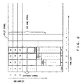
- Fig. 2 shows how each modulation signal symbol is arrayed in a matrix when a sub-carrier and time (time slots) are taken as the vertical and horizontal axes, respectively.
- Each modulation signal is packed into a frame.
- the frame is composed of at least data and a pilot signal.
- the number of sub-carriers is 1,024.
- a Walsh code is composed of 32 chips.
- data is composed of time slots 1 through 4
- one symbol is stored in sub-carriers 1 through 32
- one symbol is stored in sub-carriers 33 through 64 of the time slot 1 of data.
- a subsequent time slot 2 accommodates symbols in the same way, the respective multiplication methods of a Walsh code and a gold series code are different from those of time slot 1.
- 1, 024 chips of a code are generated by combining Walsh codes and gold series codes.
- symbols are multiplied after shifting by eight chips.
- symbols are multiplied after shifting by eight more chips.
- symbols are multiplied after shifting by another eight more chips. In this way, the multiplication timing of a spread code is shifted in each time slot.
- pilot signal has a different structure from that of data. For example, if a time slot n accommodates one pilot signal symbol, this pilot signal symbol is commonly accommodated for 1,024 sub-carriers.
- pilot symbols as described later, are included, for example, in one frame, but each symbol is the same.
- the Walsh code multiplication method of the pilot signal is different from that of data, which is described later.
- Fig. 3 shows the basic configuration of a receiver in an OFDM-CDMA system.
- An A/D converter 15 first converts received data from analog to digital. Then, a guard interval elimination unit (-GI unit) 16 eliminates a guard interval from the data and inputs the resulting data to an FFT (Fast Fourier Transformation) unit 17. Then, the FFT unit 17 decomposes a signal wave in time domain into frequency components by means of Fourier transformation.
- a transmitter regards user data's modulation signal symbols as frequency components and converts the user data's modulation signal symbols into signal waves in time domain by means of inverse Fourier transformation.
- the FFT unit 17 extracts frequency components from a signal wave in time domain by means of Fourier transformation, which is the reverse of inverse Fourier transformation, that is, extracts the user data' s modulation signal symbols.
- a channel prediction unit 18 uses the modulation pilot signal symbol of each of the frequency components f1 through fn obtained by the FFT unit 17, to calculate a channel prediction value.
- a channel compensation unit 19 applies channel correction to each of the frequency components f1 through fn.
- a multiplier 20 multiplies each frequency by the complex conjugate code of the gold series code used in the transmitter.
- a multiplier 21 multiplies each frequency by a Walsh code.
- the user data's modulation signal symbol is demodulated and an adder 22 adds all signals including a specific symbol.
- a symbol judger 23 judges the value of the symbol.
- a parallel/serial converter 24 converts the judged symbol value from parallel to serial and inputs the symbol values to a demodulation demapping unit 25.
- the demodulation demapping unit 25 demodulates the user data modulated in the transmitter and extracts the user data. Then, the demodulation demapping unit 25 transmits the user data to a receiving unit.
- one symbol of transmitting data is carried and transmitted on a plurality of sub-carriers. Therefore, even when a sub-carrier with a specific frequency is greatly affected by frequency-dependent fading, sometimes another sub-carrier with another frequency is seldom affected by the fading. Therefore, when the transmitted signal is decoded, the influence of frequency-dependent fading can be suppressed to a low level.
- Fig. 4 shows a guard interval
- the top section of the data of a prescribed length transmitted from a transmitter is copied and attached to the end section of the data as a guard interval (GI).
- the length of the guard interval is determined in such a way that the delay of a wave that has been delayed due to multi-path and the like and reaches a receiver can be accommodated in this guard interval.
- data and a guard interval are carried and transmitted on a plurality of sub-carriers.
- data to which Fourier transformation has been applied once is accommodated in one cycle of a sub-carrier with fundamental frequency or in one cycle of a sub-carrier with a frequency obtained by multiplying the fundamental frequency by an integer.
- the fact that in one cycle of the fundamental frequency, sub-carriers are orthogonal to one another is utilized. Therefore, in order to correctly extract each frequency component, the data of a received signal to which Fourier transformation is applied must be carried in a cycle of a sub-carrier with a frequency obtained by multiplying the fundamental frequency by an integer. Otherwise, orthogonality between sub-carriers will be destroyed. In this case, even when Fourier transformation is applied, a correct value cannot be obtained.
- ISI inter-symbol interference
- a guard interval if a guard interval is attached, a sub-carrier for carrying the guard interval is continuously connected to the end section of data and the sub-carrier is expanded by the guard interval, since the guard interval is the copy of the top section of the data of a prescribed length.
- the delay wave reaches the receiver within a delay time covered by the length of a guard interval, the Fourier transformation of both the direct and delay waves is conducted in one cycle of the fundamental frequency, even when Fourier transformation is applied to the shaded part shown in Fig. 4. Therefore, a correct value can be obtained. Since no piece of another data follows immediately after the data, there is no inter-symbol interference.
- the result of Fourier transformation of data including the delayed wave includes amplitude change and phase rotation, the amplitude change and phase rotation can be predicted and compensated for by channel prediction and channel compensation, respectively.
- Fig. 5 shows the relations among a base station, a cell and a radio wave with directivity transmitted from the base station.
- a base station 30 has its own territory, and when a mobile terminal enters the territory, the base station 30 transmits/receives radio waves to/from the mobile terminal.
- This territory is usually called a "cell" 32.
- the base station 30 can transmit across the entire cell.
- the base station 30 can divide the cell 32 into several sub-territories 31-1 through 31-5 and manage the sub-territories utilizing the directivity of each radio wave to be transmitted.
- the base station 30 allocates a different channel to each radio wave to be transmitted to each of the sub-territories 31-1 through 31-5 and distinguishes each radio wave assigning one of different Walsh codes 1 through 5 to each radio wave. Therefore, each mobile terminal receiving a radio wave from the base station 30 can specify a receiving channel and know its own sub-territory and relevant radio wave by detecting the used Walsh code.
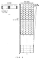
- Fig. 6 shows a pilot signal used to calculate a channel prediction value.
- Fig. 6A it is assumed that one frame accommodates four pilot signal symbols.
- An arbitrary pilot signal symbol can be arrayed in an arbitrary place.
- the four pilot signal symbols are arrayed as shown in Fig. 6A, the number of transmits is not essential to the subject matter of the preferred embodiment.
- one symbol of a pilot signal is carried on all sub-carriers for one time slot, different from the case of data. Since a time slot for which one symbol of a pilot signal is carried is determined and is different from the data symbols, a channel prediction unit extracts only a time slot including the symbol of a pilot signal and stores the time slot in a memory.
- Fig. 6B shows data stored in the memory of a channel prediction unit.
- Fig. 6B As shown in Fig. 6B, four pilot signal symbols, each of which is carried on 1, 024 sub-carriers are stored in the memory.
- the array of Walsh codes (spread code for specifying a channel (channeling)) to be multiplied to a pilot signal is also different from that of data.
- a Walsh code of 32-chip length one chip is arrayed in order for four symbols in a symbol (time slot) direction and one chip is arrayed in order for eight sub-carriers in a sub-carrier direction.
- the multiplication of such a Walsh code should be controlled in a transmitter.
- a pilot signal is repeatedly multiplied by the same block of a Walsh code composed of four symbols-by-eight sub-carriers, that is, for 1,024 sub-carriers without overlapping.
- Fig. 6B it is described as if only one Walsh code were multiplied. However, in reality, a plurality of Walsh codes are superposed and received, and are stored in the memory of a channel prediction unit since there is a possibility that a plurality of radio waves out of the radio waves with directivity covering the sub-territories 31-1 through 31-5 shown in Fig. 5 may be received.
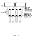
- Fig. 7 shows the basic operation in the preferred embodiment of the present invention.
- the channel prediction value of one sub-carrier is calculated by averaging those of adjacent eight sub-carriers.
- the number of sub-carriers is not limited to eight, each of the adjacent sub-carriers must have a frequency close to that of the sub-carrier, whose channel prediction value is calculated, sufficiently to calculate a channel prediction value.
- a Walsh code of 32-chip length is used as a mutually orthogonal code and is accommodated in the four symbols -by-eight channels.
- the first channel prediction value can be obtained as follows. First, the values of four symbols for each of the first to eighth sub-carriers of a pilot signal stored in the memory of a channel prediction unit are obtained by multiplying each of the four symbols by the Walsh code shown in Fig. 6B and the obtained values are added for the four symbol-by-eight sub-carriers.
- the channel prediction value of a subsequent sub-channel can be obtained by shifting the block by one row, multiplying each of the four symbols by a Walsh code and adding the obtained values for the four symbol-by-eight channels in the same way.
- the channel prediction value of a sub-channel is calculated after sequentially shifting a target block, whose channel prediction values are calculated.
- a pilot signal stored in the memory of a channel prediction unit is multiplied by a plurality of Walsh codes for a plurality of channels and the plurality of multiplied pilot signals is superposed.
- a specific Walsh code only a specific channel can be extracted.
- Fig. 6B if a block is shifted by one row, the rows are simply replaced and the first through fourth chips of a Walsh code are located at the bottom. If a reading position is changed, the pastern of the Walsh code included in a block is the same. Therefore, even when a target block is shifted by one row, the target channel can be extracted. When shifting a subsequent target block by one row in order, the same fact applies.
- the channel prediction value of each sub-channel is calculated by shifting a block covering signals, whose channel prediction values are calculated and averaged, sequentially, utilizing the fact.
- eight carriers of sub-carriers centered on the sub-carrier to which channel prediction is applied, can be added and averaged, and accordingly, a high-accuracy channel prediction value can be obtained.
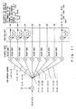
- Fig. 8 shows the flow of a pilot signal and the calculation process of a channel prediction value in the preferred embodiment.
- two Walsh codes 1 and 2 are prepared in a transmitter in order to distinguish channels from each other, as shown as (1) in Fig. 8. If it is assumed that a pilot signal's symbol pattern is, for example, (1+i) (i: imaginary unit), the symbol pattern is multiplied by each of Walsh codes 1 and 2 and the products are prepared as shown as (2) in Fig. 8. Then, at the transmitting stage, the products of the two pilot signal's symbol patterns of each of Walsh codes 1 and 2 are added (see (3) of Fig. 8) and transmitted.
- the transmitted signal undergoes a channel fluctuation while propagating in the air and individual signal values undergo a fluctuation.
- a receiver receives the signal that has undergone such a channel fluctuation.
- this signal is multiplied by a Walsh code for each block as shown in Fig. 6B and the signal values of all the sub-carriers are obtained for four symbols of a pilot signal (see (5) of Fig. 8).
- a pilot signal symbol is multiplied by a Walsh code after shifting a block by one row and the products are added for eight sub-carriers.
- a Walsh code can also be multiplied for each block after signal values for all symbols by all sub-carriers of a pilot signal to be used to calculate a channel prediction value are stored in a memory and the like.
- channel prediction value ⁇ 1 is obtained by selecting a block of four symbols -by-eight sub-carriers from the product obtained by multiplying the block by a Walsh code and adding all the signal values included in this block.
- channel prediction value ⁇ 2 is obtained by multiplying a subsequent block by a Walsh code after shifting the block by one sub-carrier and adding all the signal values in the block according to the preferred embodiment of the channel prediction value calculation method of the present invention shown in Fig. 7.
- Channel estimation value ⁇ 3 and the like are obtained in the same way.
- Each channel estimation value calculated in this way is used as the channel prediction value of each sub-carrier.
- the fourth sub-carrier of eight sub-carriers, whose channel prediction values are averaged is made to fall on the sub-carrier, whose channel prediction value is calculated.
- channel prediction value ⁇ 1 is used for the first three sub-carriers 1 through 3. Since sub-carrier 4 falls on the fourth sub-carrier when channel prediction value ⁇ 1 is calculated, the channel prediction value ⁇ 1 is used for the fourth sub-carrier.
- Channel prediction value ⁇ 2 obtained after shifting a target block by one row is used for sub-carrier 5.
- channel estimation value ⁇ 3 is used for sub-carrier 6. In sub-carriers located close to the end, the same phenomenon as that of each of sub-carriers 1 through 3 occurs. In this case too, a channel prediction value obtained last is used for the last several sub-carriers.
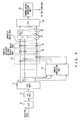
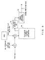
- Fig. 9 shows the configuration of a channel prediction unit used in the preferred embodiment of the present invention.
- the channel prediction unit multiplies the data by a long code (LC) (corresponding to complex conjugate of a gold series code in Fig. 3) in order to separate cells and extracts the pilot signal data of the target cell. Then, the pilot signal data of the separated cell is multiplied by a short code for pilot (corresponding to a Walsh code; the multiplication method is as has been already described in Figs. 6 through 8) read from a table. The product is stored in a pilot buffer 40.
- LC long code
- a short code for pilot corresponding to a Walsh code
- a pilot shift averaging unit 41 reads the signal values stored in the pilot buffer 40 for a unit block, whose channel prediction values are calculated. Then, the read signal values for a block are added and stored in a channel prediction buffer 42. Then, the signal values are output from the channel prediction unit as the channel prediction values.
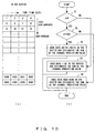
- Fig. 10 is a flowchart showing the operation of the pilot shift averaging unit 41 shown in Fig. 9 and also shows data in the pilot buffer shown in Fig. 9.
- data for four time slots (corresponding to four symbols of a pilot signal) and data for 1,024 sub-carriers are vertically and horizontally, respectively, stored in the pilot buffer.
- the data has been already multiplied by a Walsh code.
- step S1 the pilot shift averaging unit 41 judges whether n > 4. If the judgment in step S1 is no, in step S3, data 1 through 32 in the pilot buffer are added and this sum is designated as the channel prediction value. Then, the process terminates.
- step S1 If the judgment in step S1 is yes, in step S2, it is further judged whether n ⁇ 1,022. If the judgment in step S2 is no, in step S4, data 4,065 through 4,096 in the pilot buffer are added and this sum is designated as the channel prediction value. Then, the process terminates.
- step S2 If the judgment in step S2 is yes, data 4n-15 through 4n+16 are added and this sum is designated as the channel prediction value. Then, the process terminates.
- the channel prediction value of the n-th sub-carrier is calculated in this way, the channel prediction values of all the sub-carriers can be obtained by repeating the same calculation from when n starts with 1 until n reaches 1,024.
- Fig. 11 shows another preferred embodiment of a channel estimation value calculation method.
- each set is multiplied by a Walsh code.
- a Walsh code is multiplied without delay.
- a gold series code and a Walsh code are used for a spread code for separating cells and a spread code for channeling, respectively, the spread code for separating cells and that for channeling are not limited to the gold series code and Walsh code, respectively.
- one frame accommodates four symbols
- the number of symbols accommodated in one frame is not limited to four.
- the number of sub-carriers is 1,024, it is not limited to this number. For example, it can be it's half, that is, 512.
- a Walsh code is 32 chip long, it is not limited to this length and a person having ordinary skill in the art should appropriately select it.
- a high-accuracy channel prediction value that is averaged in time and sub-carrier directions can be efficiently obtained for each sub-carrier.
Landscapes
- Engineering & Computer Science (AREA)
- Signal Processing (AREA)
- Computer Networks & Wireless Communication (AREA)
- Power Engineering (AREA)
- Mobile Radio Communication Systems (AREA)
Abstract
Description
Claims (18)
- A channel prediction device using a plurality of sub-carriers in a CDMA system, comprising:extraction/despreading means for extracting a pilot signal from a received signal, eliminating spreading by a spread code for separating cells by means of despreading and outputting the signal;block despreading means for applying despreading to a block composed of a plurality of output symbols and a plurality of adjacent sub-carriers obtained by the extraction/despreading means in order to eliminate spreading by a spread code for channeling; andchannel prediction means for obtaining a channel prediction value by adding output signal values obtained by the block despreading means across the block.
- The channel prediction device according to claim 1, wherein the channel prediction value can be obtained for each sub-carrier.
- The channel prediction device according to claim 2, wherein an output position of a block obtained by the extraction/despreading means is set in such a way that a sub-carrier, whose channel prediction value is calculated, may be located in almost the center of a sub-carrier direction of an array of the block.
- The channel prediction device according to claim 2, wherein a channel prediction value is obtained by storing output of the extraction/despreading means needed to calculate a channel prediction value, as a signal value in advance, eliminating spreading by the spread code for channeling by means of despreading and adding signal values in a block located in such a way that a sub-carrier, whose channel prediction value is calculated, may be located in almost the center of a sub-carrier direction of an array of the block.
- The channel prediction device according to claim 1, wherein the spread code for channeling is a Walsh code.
- The channel prediction device according to claim 5, wherein the Walsh code is 32 chips long.
- The channel prediction device according to claim 1, wherein the spread code for separating cells is a gold series code.
- The channel prediction device according to claim 1, wherein the pilot signal accommodates four symbols in its data frame.
- The channel prediction device according to claim 1, wherein the size of the block is four symbols-by-eight sub-carriers.
- A channel prediction method using a plurality of sub-carriers in a CDMA system, comprising the steps of:extracting a pilot signal from a received signal, eliminating spreading by a spread code for separating cells by means of despreading and outputting the signal;applying despreading to a block composed of a plurality of output symbols and a plurality of adjacent sub-carriers obtained by the extraction/despreading step in order to eliminate spreading by a spread code for channeling; andobtaining a channel prediction value by adding output signal values obtained by the block despreading step across the block.
- The channel prediction method according to claim 10, wherein the channel prediction value can be obtained for each sub-carrier.
- The channel prediction method according to claim 11, wherein an output position of a block obtained by the extraction/despreading step is set in such a way that a sub-carrier, whose channel prediction value is calculated, may be located in almost the center of a sub-carrier direction of an array of the block.
- The channel prediction method according to claim 11, wherein the channel prediction value is obtained by storing output of the extraction/despreading step as a signal value in advance in order to calculate a channel prediction value, eliminating spreading by the spread code for channeling by means of despreading and adding signal values in a block located in such a way that a sub-carrier, whose channel prediction value is calculated, may be located in almost the center of a sub-carrier direction of an array of the block.
- The channel prediction method according to claim 10, wherein the spread code for channeling is a Walsh code.
- The channel prediction method according to claim 14, wherein the Walsh code is 32 chips long.
- The channel prediction method according to claim 10, wherein the spread code for separating cells is a gold series code.
- The channel prediction method according to claim 10, wherein the pilot signal accommodates four symbols in its data frame.
- The channel prediction method according to claim 10, wherein the size of the block is four symbols-by -eight sub-carriers.
Applications Claiming Priority (1)
| Application Number | Priority Date | Filing Date | Title |
|---|---|---|---|
| PCT/JP2001/008541 WO2003032546A1 (en) | 2001-09-28 | 2001-09-28 | Channel inferring device and method |
Publications (3)
| Publication Number | Publication Date |
|---|---|
| EP1432163A1 true EP1432163A1 (en) | 2004-06-23 |
| EP1432163A4 EP1432163A4 (en) | 2006-05-17 |
| EP1432163B1 EP1432163B1 (en) | 2012-11-28 |
Family
ID=11737778
Family Applications (1)
| Application Number | Title | Priority Date | Filing Date |
|---|---|---|---|
| EP20010972583 Expired - Lifetime EP1432163B1 (en) | 2001-09-28 | 2001-09-28 | Channel estimation device and method |
Country Status (5)
| Country | Link |
|---|---|
| US (1) | US8432998B2 (en) |
| EP (1) | EP1432163B1 (en) |
| JP (1) | JP4323313B2 (en) |
| CN (1) | CN100566222C (en) |
| WO (1) | WO2003032546A1 (en) |
Families Citing this family (7)
| Publication number | Priority date | Publication date | Assignee | Title |
|---|---|---|---|---|
| US7830782B2 (en) * | 2004-05-10 | 2010-11-09 | Qualcomm Incorporated | Method of using guard tones in OFDM systems for increasing robustness |
| KR100739511B1 (en) * | 2004-06-25 | 2007-07-13 | 삼성전자주식회사 | Apparatus and method for transmitting/receiving pilot signal in a communication system using orthogonal frequency division multiplexing scheme |
| US7522555B2 (en) * | 2005-01-21 | 2009-04-21 | Intel Corporation | Techniques to manage channel prediction |
| JP4264550B2 (en) * | 2005-11-15 | 2009-05-20 | ソニー株式会社 | Reception device and channel estimation device |
| US8472309B2 (en) * | 2008-08-20 | 2013-06-25 | Qualcomm Incorporated | Using CDMA to send uplink signals in WLANs |
| US9130786B2 (en) | 2013-03-15 | 2015-09-08 | Qualcomm Incorporated | Device and method for computing a channel estimate |
| JP7387076B2 (en) * | 2021-11-26 | 2023-11-27 | 三菱電機株式会社 | Communication devices, communication systems, communication methods, control circuits, and storage media |
Family Cites Families (18)
| Publication number | Priority date | Publication date | Assignee | Title |
|---|---|---|---|---|
| JP3457357B2 (en) * | 1993-07-23 | 2003-10-14 | 株式会社日立製作所 | Spread spectrum communication system, transmission power control method, mobile terminal device, and base station |
| FI102577B1 (en) * | 1996-09-05 | 1998-12-31 | Nokia Telecommunications Oy | Transmission and reception procedure and radio system |
| US6810030B1 (en) * | 1997-10-17 | 2004-10-26 | Lucent Technology | Dynamic and smart spreading for wideband CDMA |
| US6366607B1 (en) * | 1998-05-14 | 2002-04-02 | Interdigital Technology Corporation | Processing for improved performance and reduced pilot |
| US6690652B1 (en) * | 1998-10-26 | 2004-02-10 | International Business Machines Corporation | Adaptive power control in wideband CDMA cellular systems (WCDMA) and methods of operation |
| US6452917B1 (en) * | 1999-04-08 | 2002-09-17 | Qualcomm Incorporated | Channel estimation in a CDMA wireless communication system |
| US6925067B2 (en) * | 1999-04-23 | 2005-08-02 | Qualcomm, Incorporated | Configuration of overhead channels in a mixed bandwidth system |
| US6621808B1 (en) * | 1999-08-13 | 2003-09-16 | International Business Machines Corporation | Adaptive power control based on a rake receiver configuration in wideband CDMA cellular systems (WCDMA) and methods of operation |
| US6785350B1 (en) * | 1999-10-14 | 2004-08-31 | Nokia Corporation | Apparatus, and associated method, for detecting a symbol sequence |
| EP1158708A4 (en) * | 1999-12-28 | 2007-01-03 | Ntt Docomo Inc | PATH SEARCH METHOD, CHANNEL ESTIMATING METHOD, AND COMMUNICATION DEVICE |
| EP1128592A3 (en) * | 2000-02-23 | 2003-09-17 | NTT DoCoMo, Inc. | Multi-carrier CDMA and channel estimation |
| KR100370746B1 (en) * | 2000-05-30 | 2003-02-05 | 한국전자통신연구원 | Multi-Dimensional Orthogonal Resource Hopping Multiplexing Communications Method and Apparatus thereof |
| KR100526499B1 (en) * | 2000-08-22 | 2005-11-08 | 삼성전자주식회사 | Apparatus for transmit diversity for more than two antennas and method thereof |
| US7233625B2 (en) * | 2000-09-01 | 2007-06-19 | Nortel Networks Limited | Preamble design for multiple input—multiple output (MIMO), orthogonal frequency division multiplexing (OFDM) system |
| US6940827B2 (en) * | 2001-03-09 | 2005-09-06 | Adaptix, Inc. | Communication system using OFDM for one direction and DSSS for another direction |
| US7035201B2 (en) * | 2001-04-20 | 2006-04-25 | Mediatek Inc. | Programmable transceiver structure of multi-rate OFDM-CDMA for wireless multimedia communications |
| US20050013350A1 (en) * | 2001-06-06 | 2005-01-20 | Coralli Alessandro Vanelli | Method and apparatus for canceling pilot interference in a wireless communication system |
| US6927728B2 (en) * | 2003-03-13 | 2005-08-09 | Motorola, Inc. | Method and apparatus for multi-antenna transmission |
-
2001
- 2001-09-28 EP EP20010972583 patent/EP1432163B1/en not_active Expired - Lifetime
- 2001-09-28 JP JP2003535384A patent/JP4323313B2/en not_active Expired - Fee Related
- 2001-09-28 WO PCT/JP2001/008541 patent/WO2003032546A1/en not_active Ceased
- 2001-09-28 CN CNB018235344A patent/CN100566222C/en not_active Expired - Fee Related
-
2003
- 2003-12-19 US US10/739,144 patent/US8432998B2/en not_active Expired - Fee Related
Also Published As
| Publication number | Publication date |
|---|---|
| JPWO2003032546A1 (en) | 2005-01-27 |
| EP1432163A4 (en) | 2006-05-17 |
| JP4323313B2 (en) | 2009-09-02 |
| US20040131022A1 (en) | 2004-07-08 |
| CN100566222C (en) | 2009-12-02 |
| WO2003032546A1 (en) | 2003-04-17 |
| EP1432163B1 (en) | 2012-11-28 |
| CN1543721A (en) | 2004-11-03 |
| US8432998B2 (en) | 2013-04-30 |
Similar Documents
| Publication | Publication Date | Title |
|---|---|---|
| TWI389470B (en) | Reverse link pilot transmission for a wireless communication system | |
| TW393841B (en) | Method and system for processing a plurality of multiple access transmissions | |
| JP3553038B2 (en) | Signal transmission method, signal reception method, transmission device, reception device, and recording medium | |
| RU2462817C1 (en) | Method to send pilot signal, basic station, mobile station and cellular communication system, where such method is applied | |
| EP1128592A2 (en) | Multi-carrier CDMA and channel estimation | |
| KR101425326B1 (en) | Base station apparatus and wireless communication method | |
| US7023903B2 (en) | Method of receiving spread spectrum signal, and receiver | |
| US20050088960A1 (en) | Apparatus and method for transmitting/receiving pilot pattern set to distinguish base station in orthogonal frequency division multiplexing (OFDM) communication system | |
| CN100477569C (en) | Method, transmitter and receiver using long code and short code multicarrier CDMA scheme | |
| KR20080028932A (en) | Transmitter, Receiver, Mobile Communication System and Synchronous Channel Transmission Method | |
| WO2003049344A1 (en) | Multi-carrier transmission/reception apparatus | |
| WO2001050655A1 (en) | Signal format in multi-carrier cdma transmission system | |
| KR20070020292A (en) | Radio transmitter, radio receiver and symbol placement method | |
| JP2004357326A (en) | Method for displaying set of codes belonging to base station in time division duplex (tdd) communication system | |
| CN101036311B (en) | CDMA radio system using pilot signal and adaptive filter | |
| US8432998B2 (en) | Device for channel estimation in a multiple subcarrier CDMA system using a block of multiple subcarriers by multiple symbols and method thereof | |
| JP4614977B2 (en) | Transmission method and transmission apparatus in OFDM-CDMA communication system | |
| JP5024548B2 (en) | Control signal demodulating device, control signal demodulating method, radio communication device, and program | |
| KR100871265B1 (en) | Transmission/rece apparatus and method for supporting both high rate packet data transmission and orthogonal frequency division multiplexing transmission in a mobile communication system | |
| KR20050075553A (en) | Uplink pilot construction method for multicarrier code division multiple access system | |
| JP2003152681A (en) | Mobile communication system and method using multi-carrier CDMA system using scramble code | |
| JP2002232327A (en) | Path selection method and circuit used for receiver | |
| JP2003101511A (en) | Multi-carrier spread spectrum communication apparatus and communication system thereof | |
| JP4571152B2 (en) | Wireless communication apparatus and data multiplexing method | |
| US6788669B1 (en) | CDMA demodulating apparatus and method and CDMA mobile communication system |
Legal Events
| Date | Code | Title | Description |
|---|---|---|---|
| PUAI | Public reference made under article 153(3) epc to a published international application that has entered the european phase |
Free format text: ORIGINAL CODE: 0009012 |
|
| 17P | Request for examination filed |
Effective date: 20040112 |
|
| AK | Designated contracting states |
Kind code of ref document: A1 Designated state(s): DE FR GB IT |
|
| A4 | Supplementary search report drawn up and despatched |
Effective date: 20060404 |
|
| RIC1 | Information provided on ipc code assigned before grant |
Ipc: H04L 25/02 20060101ALI20060329BHEP Ipc: H04L 5/02 20060101AFI20060329BHEP |
|
| 17Q | First examination report despatched |
Effective date: 20061204 |
|
| RTI1 | Title (correction) |
Free format text: CHANNEL ESTIMATION DEVICE AND METHOD |
|
| GRAP | Despatch of communication of intention to grant a patent |
Free format text: ORIGINAL CODE: EPIDOSNIGR1 |
|
| GRAS | Grant fee paid |
Free format text: ORIGINAL CODE: EPIDOSNIGR3 |
|
| GRAA | (expected) grant |
Free format text: ORIGINAL CODE: 0009210 |
|
| AK | Designated contracting states |
Kind code of ref document: B1 Designated state(s): DE FR GB IT |
|
| REG | Reference to a national code |
Ref country code: GB Ref legal event code: FG4D |
|
| REG | Reference to a national code |
Ref country code: DE Ref legal event code: R096 Ref document number: 60147442 Country of ref document: DE Effective date: 20130124 |
|
| PLBE | No opposition filed within time limit |
Free format text: ORIGINAL CODE: 0009261 |
|
| STAA | Information on the status of an ep patent application or granted ep patent |
Free format text: STATUS: NO OPPOSITION FILED WITHIN TIME LIMIT |
|
| PGFP | Annual fee paid to national office [announced via postgrant information from national office to epo] |
Ref country code: DE Payment date: 20130626 Year of fee payment: 13 |
|
| 26N | No opposition filed |
Effective date: 20130829 |
|
| PGFP | Annual fee paid to national office [announced via postgrant information from national office to epo] |
Ref country code: GB Payment date: 20130702 Year of fee payment: 13 Ref country code: FR Payment date: 20130821 Year of fee payment: 13 |
|
| REG | Reference to a national code |
Ref country code: DE Ref legal event code: R097 Ref document number: 60147442 Country of ref document: DE Effective date: 20130829 |
|
| PG25 | Lapsed in a contracting state [announced via postgrant information from national office to epo] |
Ref country code: IT Free format text: LAPSE BECAUSE OF NON-PAYMENT OF DUE FEES Effective date: 20130928 |
|
| REG | Reference to a national code |
Ref country code: DE Ref legal event code: R119 Ref document number: 60147442 Country of ref document: DE |
|
| GBPC | Gb: european patent ceased through non-payment of renewal fee |
Effective date: 20140928 |
|
| REG | Reference to a national code |
Ref country code: DE Ref legal event code: R119 Ref document number: 60147442 Country of ref document: DE Effective date: 20150401 |
|
| REG | Reference to a national code |
Ref country code: FR Ref legal event code: ST Effective date: 20150529 |
|
| PG25 | Lapsed in a contracting state [announced via postgrant information from national office to epo] |
Ref country code: DE Free format text: LAPSE BECAUSE OF NON-PAYMENT OF DUE FEES Effective date: 20150401 Ref country code: GB Free format text: LAPSE BECAUSE OF NON-PAYMENT OF DUE FEES Effective date: 20140928 |
|
| PG25 | Lapsed in a contracting state [announced via postgrant information from national office to epo] |
Ref country code: FR Free format text: LAPSE BECAUSE OF NON-PAYMENT OF DUE FEES Effective date: 20140930 |