EP1432135A1 - Système et procédé de détection de présence et de synchronisation d'un signal pour un système à sauts de fréquence fonctionnant en environnement perturbé - Google Patents
Système et procédé de détection de présence et de synchronisation d'un signal pour un système à sauts de fréquence fonctionnant en environnement perturbé Download PDFInfo
- Publication number
- EP1432135A1 EP1432135A1 EP03104214A EP03104214A EP1432135A1 EP 1432135 A1 EP1432135 A1 EP 1432135A1 EP 03104214 A EP03104214 A EP 03104214A EP 03104214 A EP03104214 A EP 03104214A EP 1432135 A1 EP1432135 A1 EP 1432135A1
- Authority
- EP
- European Patent Office
- Prior art keywords
- signal
- value
- frequency
- largest
- une
- Prior art date
- Legal status (The legal status is an assumption and is not a legal conclusion. Google has not performed a legal analysis and makes no representation as to the accuracy of the status listed.)
- Granted
Links
Images





Classifications
-
- H—ELECTRICITY
- H04—ELECTRIC COMMUNICATION TECHNIQUE
- H04B—TRANSMISSION
- H04B1/00—Details of transmission systems, not covered by a single one of groups H04B3/00 - H04B13/00; Details of transmission systems not characterised by the medium used for transmission
- H04B1/69—Spread spectrum techniques
- H04B1/713—Spread spectrum techniques using frequency hopping
- H04B1/7156—Arrangements for sequence synchronisation
-
- H—ELECTRICITY
- H04—ELECTRIC COMMUNICATION TECHNIQUE
- H04B—TRANSMISSION
- H04B1/00—Details of transmission systems, not covered by a single one of groups H04B3/00 - H04B13/00; Details of transmission systems not characterised by the medium used for transmission
- H04B1/69—Spread spectrum techniques
- H04B1/713—Spread spectrum techniques using frequency hopping
- H04B1/7156—Arrangements for sequence synchronisation
- H04B2001/71563—Acquisition
Definitions
- the invention applies in particular to jump systems of frequencies that operate at very low signal-to-noise ratios (typically those who use artificial satellites as a relay) and, for these systems, to the acquisition function which consists, for a participant entering the network - therefore not synchronized - to detect the presence of known signals emitted at known times and frequencies.
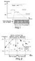
- Figure 1 shows the principle of a jump system of frequency where the occupied band is limited by two extreme frequencies F1 and F2 in front operating at very low signal-to-noise ratios (typically those who use artificial satellites as a relay) and for these systems, to the acquisition function which consists, for a participant entering the network - therefore not synchronized - to detect the presence of known signals emitted at known times and frequencies.
- Each level has N elements carrying information or not called symbols, preceded (or followed, whatever) by a guard time intended both to minimize interference between users approximately synchronized and allow the receiver time to "stabilize” at each new frequency (gain control, positioning of the frequency synthesizer, filter tracking, ).
- time was divided into basic patterns of constant duration, each pattern not having than a reference bearing arranged at a position known in advance.
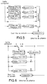
- FIG. 3 represents the action of the receptor during the phase of research, that is to say when he does not yet know the "time to reference "of the system he wants to access.
- the receiver uses a detection system presence as described in figure 4.
- a pseudo-random generator delivers, depending on the time local receiver the number of the standby frequency to be used as well as a binary train from which the known part of the expected signal is reconstructed on the reference level that we hope to detect, the unknown part being reset.
- the output of the correlator at time to is then given by: either again: that is to say G times the sum of the squares of the modules of the reference symbols plus a random noise.
- Corr (to) is the maximum of the correlator output.
- a fixed or adjustable threshold is set on the correlator output. If this threshold is exceeded, the receiver declares that it has "acquired” the reference and notes the time of the overshoot from which it will deduce the time adjustment to be made.
- Figure 5 shows schematically an exemplary embodiment according to the art prior.
- Receiver attempts to recombine correlator outputs collected during all (or almost) the duration of the watch on the frequencies F (1), F (2), ..., F (M). Note that these are the raw outputs of the correlator, and that the detection threshold mentioned above is not used.
- This embodiment is very expensive in terms of memory, especially if the product of the sampling rate (proportional to the modulation speed, standby time (proportional to uncertainty time) and the number of frequencies to watch (all the more important as reception conditions are more severe) is important (several tens or hundreds of thousands).
- this embodiment does not avoid the need possible to cover several Doppler boxes therefore, to realize the system at several copies, each one assigned to a Doppler cell.
- the system and method according to the invention are based on a new approach to signal processing.
- Figure 7 shows an example of a system architecture allowing initial signal synchronization for a low S / N ratio and / or in the presence of jammers, with a large frequency offset unknown.
- the system includes for example a device 100, or soft limiter adapted to control the level of the signal S received by a receiver of the system, a device 200 for estimating the signal energy, a differential demodulator 300 receiving the signal and generating a signal differential to a 400 Doppler correlator which also receives a signal of reference R, a device 500 for normalizing the signal Sc from the correlator according to the estimated energy, several devices memorization 6i0, where i is the index of the frequency concerned, a summator 700 and a comparator 800 receiving on the one hand the value of a threshold at respect and on the other hand the signal from the adder.
- a device 100 or soft limiter adapted to control the level of the signal S received by a receiver of the system
- a device 200 for estimating the signal energy
- a differential demodulator 300 receiving the signal and generating a signal differential to a 400 Doppler correlator which also receives a signal of reference R
- a device 500 for normalizing the signal Sc
- the input signal S which can have a strong dynamic passes through first the "soft" limiter 100 whose effect is equivalent to a control automatic high gain (AGC) which preserves the linearity of the reception.
- AGC automatic high gain
- the output of the soft limiter is subject for example to an estimate permanent and slippery signal energy that will be contained in the correlator thanks to device 200.
- a differential demodulator 300 uses the samples of the output signal of the soft limiter to generate the differential signal, represented by its two ReDem (real part) and ImDem (imaginary part) components.
- the output of the differential demodulator represents the input of the correlator "with Doppler boxes" 400, correlator designed to work with a real reference signal (generally, series of +1 and -1).
- the correlator output is renormalized by the 500 system in function of the signal energy present in the correlator and calculated in permanently by the device 200 already mentioned.
- the process keeps in memory only the K largest output values, values where the correlation peak is most likely to occur, as well as their l positions corrected by the theoretical position of the reference bearing T (1) .. T (M) in memory devices numbered 610, 620, ..., 6M0.
- the 700 system is responsible for sum the stored amplitudes whose (corrected) positions l are identical and memorizes the value of the largest sum and the position corresponding.
- comparator 800 compares to a more fixed threshold large sum and decides on the presence of the signal if it has exceeded the threshold.
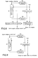
- FIG. 8 represents a detailed example of embodiment of the device 100 called "soft limiter". The idea is to conserve energy mean in a given range of values [Emin, Emax].
- the output of the accumulator is then supplied to a logic of offset calculation 105 which applies an offset to the shifter 106 such that the accumulator output as close as possible to a set value given. This value depends on the hardware implementation envisaged.
- the shifter 106 outputs a limited complex signal of in a gentle way or, if you prefer, whose level is regulated by an "almost instant" AGC.
- the (constant) output level can vary by a factor of 2 depending on the values taken by entry level.
- the central sample constituting the output of the "soft limiter" will be to be multiplied by the gain g, whether or not g has been modified.
- Emin and Emax are adjusted according to the characteristics of the material, i.e. the values not to be exceeded in the following treatments.
- n In the case of a "fixed point" implementation (using whole numbers), the value of n will preferably be equal to 2, knowing that a multiplication or a division by 2 results in a simple shift left or right.
- Figure 9 shows an example of an estimation device slippery signal energy.
- This delay line is dimensioned so that it contains at all times all of the samples participating in the correlations (Doppler boxes).
- a simple variant (not shown here for reasons of simplification) consists in storing in the delay line the squares of modules themselves and add the module square to the accumulator entering the delay line and subtracting the square from the outgoing module. This saves element 203 for example.
- Figure 10 shows schematically an example of differential demodulator.
- a delay line 301 achieves a delay equal to the time difference between two successive references.
- a 302 "conjugator" and a multiplier complex 303 are responsible for delivering the real part separately (ReDem) and the imaginary part (ImDem) of the differentially demodulated signal which will be recombined before correlation with a reference signal R.
- Figure 11 is a first detailed example of a correlator to Doppler boxes with 3 Doppler boxes.
- Figure 12 shows a second detailed example of a "Doppler case" correlator
- the correlation being a linear operation
- FIG. 13 describes an example of a device making it possible to normalize the output of the correlators.
- Elements 501 and 502 are used to find the offset that allows transform the sliding estimate of the energy of the signal participating in the correlation to a valid address in the inverse table 503.
- the non-normalized output of the i-th correlator is multiplied in a suitable device 504 by the output of the table, and undergoes a shift by the shifter 505 which allows to restore the (approximate) value that we would have obtained by a true division, namely the output of the i-th correlator normalized.
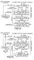
- Figure 14 shows an example of a device for memorize the K largest values on F (m). We memorize the couples (amplitudes and positions -T (m)).
- the memory 6m1 contains the amplitude + time position pairs of the K largest correlations appeared until then.
- the 6m2 memory contains the amplitude of the correlation the lowest contained in the 6m1 memory, as well as its address in this memory.
- the whole is under the control of a 6m4 control logic which is also responsible for initializing the system at the start of the search.
- FIG. 15 represents a variant of FIG. 14.
- a 6m1b memory contains the pairs (amplitude, position) systematically arranged in order of increasing amplitudes.
- the value a (0) represents the amplitude stored at address 0, which is the smallest of all.
- the 6m3b system is responsible for modify the contents of the 6m1b memory so that the new amplitude is put in the right place, it being understood that the amplitude a0 (and the corresponding position) will have been eliminated.
- Figure 16 describes an example of a final summation system of the different "greatest values retained”.
- the final summation system below shows in form flowchart the process which allows, from the content of the memories of the device 600, to decide on the absence or presence of the bearings reference on the M frequencies.
- the amplitudes are added corresponding to the same position at this frequency (step 705) and within following.
- the final output value is the "MAX correlation” value, accompanied by "pos MAX”. It is this which is compared to the fixed threshold in comparator 800 to decide whether or not the signal (the references) was present and, if so, at what time position.
Landscapes
- Engineering & Computer Science (AREA)
- Computer Networks & Wireless Communication (AREA)
- Signal Processing (AREA)
- Radar Systems Or Details Thereof (AREA)
- Mobile Radio Communication Systems (AREA)
- Synchronisation In Digital Transmission Systems (AREA)
- Stabilization Of Oscillater, Synchronisation, Frequency Synthesizers (AREA)
- Burglar Alarm Systems (AREA)
- Digital Transmission Methods That Use Modulated Carrier Waves (AREA)
- Noise Elimination (AREA)
Abstract
- Pour chaque fréquence F(1)...F(M), sélectionner les K échantillons correspondant aux plus grandes valeurs du signal, (repérés par une amplitude et une position corrigée d'une quantité connue (T(1)...T(M)),
- Combiner pour une position donnée et sur les différentes fréquences la valeur sélectionnée parmi K correspondant à la dite position et conserver la plus grande valeur combinée et la position correspondante,
- Comparer la plus grande valeur combinée à une valeur seuil, si elle est supérieure à cette valeur seuil, alors décréter la détection du signal.
Description
- L'étalement de spectre par élargissement de la bande généralement obtenu en sur-modulant le signal d'origine par une séquence pseudo aléatoire synchrone avec les données et ayant un débit voisin de la largeur totale de bande occupée,
- L'étalement de spectre par sauts de fréquence (FH - frequency hopping ou EVF Evasion de Fréquence) qui consiste à émettre le signal par « paliers » de durée fixe, et en changeant de fréquence de manière pseudo aléatoire dans toute la bande occupée.
- le signal reçu comporte bien les bons symboles de référence aux positions attendues,
- le signal reçu est parfaitement "calé" dans le corrélateur, i.e. chaque symbole de référence reçu est "en face" du symbole de référence attendu.



- il effectue une sommation point à point des sorties des M mémoires, chacune retardée de la quantité adéquate (les lignes à retard ne sont pas "physiquement" indispensables: elles peuvent être remplacées par des décalages appropriés dans les adresses de lecture en mémoire),
- il réalise une comparaison de toutes les sommes obtenues à un seuil fixe ou variable pour détecter la présence du signal, ainsi que son décalage temporel.
- sur la première fréquence de veille, on se contente de stocker directement le signal issu du corrélateur;
- sur les fréquences suivantes, on additionne la sortie du corrélateur retardée de la quantité adéquate aux corrélations déjà mémorisées;
- sur la dernière fréquence, la sortie de l'accumulateur est comparée à un seuil pour la détection de présence.
- pour chaque fréquence F(1)...F(M), sélectionner les K échantillons correspondant aux plus grandes valeurs du signal, repérés chacun par une amplitude et une position corrigée d'un retard connu (T(1)...T(M)),
- combiner pour une position donnée les M plus grandes valeurs sélectionnées parmi K sur chaque fréquence ayant la dite position, et conserver la plus grande valeur combinée et la position correspondante,
- comparer la plus grande valeur combinée à une valeur seuil, si elle est supérieure à cette valeur seuil, alors décréter la détection du signal.
- corréler le signal reçu avec un signal de référence R,
- pour chaque fréquence F(1)...F(M), mémoriser les K plus grandes valeurs du signal et leur position corrigée d'un retard connu T(1)...T(M),
- sommer pour une position temporelle donnée les K plus grandes valeurs sélectionnées ayant cette position et conserver la somme la plus grande,
- comparer cette plus grande somme à une valeur seuil, si elle est supérieure à cette valeur seuil, alors décréter la détection du signal.
- plusieurs dispositifs de mémorisation 6i0, où i est l'indice de la fréquence concernée, les dispositifs étant adaptés à mémoriser les K plus grandes valeurs pour une fréquence donnée ainsi que leur position,
- un dispositif de combinaison permettant de combiner, position par position, les K plus grandes valeurs pour toutes les valeurs de fréquence et de conserver la plus grande valeur,
- un comparateur recevant d'une part la valeur d'un seuil à respecter et d'autre part la plus grande valeur.
- une structure de système d'acquisition nécessitant le moins de puissance de calcul et le moins de mémoire possible, au prix d'une dégradation des performances aussi faible que possible par rapport au dispositif théorique optimal,
- selon une variante de réalisation, le système de régulation d'entrée est incorporé au dispositif, sachant que, dans les applications visées (de plus en plus dans l'avenir), la partie amont du récepteur est (au moins partiellement) réalisée sous forme numérique et que le signal d'entrée n'est que grossièrement régulé, par exemple juste pour éviter des saturations dans les étages intermédiaires,
- un système de régulation le plus simple et le plus efficace possible.
- Les figures 1 à 4 des schémas des principes d'émission et de synchronisation selon l'art antérieur,
- Les figures 5 et 6 deux exemples d'architecture de système selon l'art antérieur,
- La figure 7 un exemple d'architecture d'un système selon l'invention,
- Les figures 8 à 16 des exemples détaillés des différents éléments constituant le système de la figure 7.
- Soit Et la valeur d'énergie du signal pour un instant t donné,
- Soit G un gain à appliquer à Et,
- Soit g un gain à appliquer sur l'échantillon à traiter,
Alors diviser le gain G par n2, et le gain g par n,
Sinon
Si le produit G Et est inférieur ou égal à Emin,
Alors multiplier le gain G par n2, et le gain g par n
Sinon
la valeur Et est comprise entre Emin et Emax, et il n'y a pas lieu de modifier les gains G et g.
- l'angle teta correspond à la rotation de phase entre deux symboles de référence pour la case Doppler considérée,
- comp(x) désigne une fonction dépendant du système, et donnant un nombre réel pouvant être selon le cas la partie réelle, la partie imaginaire, ou une autre fonction de la quantité x. Cette fonction est choisie pour que la corrélation puisse être obtenue par une suite de multiplications par +/-1.
- si le nombre de case Doppler vaut 1, un seul corrélateur est nécessaire.
- s'il vaut 2, deux corrélateurs sont nécessaires.
- s'il est supérieur ou égal à 3, la variante ci-dessous (figure 12) montre comment on peut n'utiliser que deux corrélateurs dans tous les cas.
- si elle est inférieure à la valeur minimale, rien ne se passe,
- si elle est supérieure à la valeur minimale, la nouvelle corrélation remplace l'ancienne plus petite (i.e. on la stocke ainsi que sa position corrigée à son adresse) et un système 6m5 se charge de repérer parmi les K couples contenus dans la mémoire 6m1 celui dont l'amplitude est la plus faible, et d'en transférer l'adresse et l'amplitude dans la mémoire 6m2.
- Pour faire une division par n, très coûteuse en puissance de calcul, on multipliera par exemple l'entier le plus proche de 2^k/n (pré-calculé et mis dans une table), et on divisera ensuite par 2^k, ce qui se fait simplement par un décalage à droite de k positions,
- Les calculs sont effectués par exemple sur des nombres en « virgule fixe » (nombres entiers ou fractionnaires) et, moyennant certaines précautions, donnent toujours un résultat exact,
- Dans la mesure du possible, on privilégiera les multiplications ou les divisions par des puissances de 2 (décalages à gauche ou à droite) au détriment d'autres valeurs, ce qui évite de calculer les dites autres valeurs,
- La majorité des échantillons de sortie du ou des corrélateurs consiste en échantillons de « bruit » sans intérêt et ne participent en rien à la détection de présence. On cherchera donc à garder uniquement les échantillons de corrélation « dignes d'intérêt » afin d'économiser la mémoire.
Claims (10)
- Procédé de détection et de synchronisation d'un signal dans un système à sauts de fréquence caractérisé en ce qu'il comporte au moins les étapes suivantes :pour chaque fréquence F(1)...F(M), sélectionner les K échantillons correspondant aux plus grandes valeurs du signal, et leurs positions,combiner pour une position donnée, les M plus grandes valeurs sélectionnées sur chaque fréquence ayant la dite position, et conserver la plus grande valeur combinée et la position correspondante,comparer la plus grande valeur combinée à une valeur seuil, et si elle est supérieure à cette valeur seuil, décréter la détection du signal.
- Procédé selon la revendication 1 caractérisé en ce qu'il comporte au moins les étapes suivantes :limiter le niveau d'amplitude du signal reçu S,corréler le signal reçu avec un signal de référence R,pour chaque fréquence F(1)...F(M) mémoriser les K plus grandes valeurs du signal et leur position corrigée d'un retard connu T(1)...T(M),sommer pour une position temporelle donnée les K plus grandes valeurs sélectionnées ayant cette position et conserver la plus grande somme,comparer cette plus grande somme à une valeur seuil, et si elle est supérieure à cette valeur seuil, décréter la détection du signal.
- Procédé selon la revendication 2 caractérisé en ce que l'étape de limitation du niveau de signal comporte au moins les étapes suivantes :utiliser une fenêtre glissante pour sélectionner une tranche (zone) de signal,estimer l'énergie du signal sur cette tranche,faire varier le gain appliqué au signal de telle sorte qu'in fine, son énergie à court terme reste pendant la majorité du temps dans un intervalle fixe donné.
- Procédé selon la revendication 3 caractérisé en ce que l'on utilise une ligne à retard ou une mémoire circulaire comme fenêtre glissante.
- Procédé selon l'une des revendications précédentes caractérisé en ce que, pour une fréquence de veille de rang m, connaissant les paires amplitudes et position des K plus grandes valeurs apparues,si la nouvelle valeur corrélée est supérieure à la valeur minimale retenue jusqu'alors,on remplace l'ancienne valeur minimale par la nouvelle valeur corrélée,on recherche parmi les K couples celui dont l'amplitude est la plus faible eton mémorise ses paramètres (amplitude, position corrigée).
- Procédé selon l'une des revendications 1 à 5 caractérisé en ce que l'on compare la nouvelle valeur corrélée aux différentes amplitudes mémorisées dans un ordre d'amplitude croissante, et dès que cette nouvelle valeur est supérieure à une des amplitudes, on range la nouvelle valeur corrélée ainsi que sa position corrigée .
- Procédé selon l'une des revendications 1 à 6 caractérisé en ce que l'étape de combinaison comporte les étapes suivantes :initialiser à 0 une valeur « corrélation MAX »,pour chaque fréquence F(m) et pour toutes les positions mémorisées pour cette fréquence, additionner les amplitudes correspondant à la même position à cette fréquence et dans les suivantes,si la somme obtenue est supérieure à la valeur « corrélation MAX », identifier la valeur « corrélation MAX » à la somme et la position du maximum « pos MAX » à la position examinée,sélectionner la valeur finale comme étant la valeur de « corrélation MAX » accompagnée de « pos MAX », afin de déterminer la détection du signal.
- Dispositif de détection et de synchronisation d'un signal dans un système à sauts de fréquence caractérisé en ce qu'il comporte au moins les éléments suivants :plusieurs dispositifs de mémorisation 6i0, où i est l'indice de la fréquence concernée, les dispositifs étant adaptés à mémoriser les K plus grandes valeurs pour une fréquence donnée ainsi que leur position,un dispositif de combinaison 700 permettant de combiner, position par position, les K plus grandes valeurs pour toutes les valeurs de fréquence et de conserver la plus grande valeur,un comparateur 800 recevant d'une part la valeur d'un seuil à respecter et d'autre part la plus grande valeur.
- Dispositif selon la revendication 8 caractérisé en ce que le dispositif de combinaison est un sommateur.
- Dispositif selon l'une des revendications 8 et 9 caractérisé en ce qu'il comporte un limiteur doux (100) adapté à contrôler le niveau du signal et un corrélateur ( 400) qui reçoit aussi un signal de référence R.
Applications Claiming Priority (2)
| Application Number | Priority Date | Filing Date | Title |
|---|---|---|---|
| FR0214344A FR2847400B1 (fr) | 2002-11-15 | 2002-11-15 | Systeme et procede de detection de presence et de synchronisation d'un signal pour un systeme a sauts de frequence fonctionnant en environnement perturbe |
| FR0214344 | 2002-11-15 |
Publications (2)
| Publication Number | Publication Date |
|---|---|
| EP1432135A1 true EP1432135A1 (fr) | 2004-06-23 |
| EP1432135B1 EP1432135B1 (fr) | 2005-10-19 |
Family
ID=32187649
Family Applications (1)
| Application Number | Title | Priority Date | Filing Date |
|---|---|---|---|
| EP03104214A Expired - Lifetime EP1432135B1 (fr) | 2002-11-15 | 2003-11-14 | Système et procédé de détection de présence et de synchronisation d'un signal pour un système à sauts de fréquence fonctionnant en environnement perturbé |
Country Status (6)
| Country | Link |
|---|---|
| US (1) | US7366224B2 (fr) |
| EP (1) | EP1432135B1 (fr) |
| AT (1) | ATE307428T1 (fr) |
| CA (1) | CA2448847A1 (fr) |
| DE (1) | DE60301940T2 (fr) |
| FR (1) | FR2847400B1 (fr) |
Cited By (1)
| Publication number | Priority date | Publication date | Assignee | Title |
|---|---|---|---|---|
| CN111510183A (zh) * | 2020-03-25 | 2020-08-07 | 北京理工大学 | 一种相干快跳频多路并行本振相位计算方法及本振 |
Families Citing this family (3)
| Publication number | Priority date | Publication date | Assignee | Title |
|---|---|---|---|---|
| US7899107B1 (en) * | 2006-04-17 | 2011-03-01 | Marvell International Ltd. | Preamble detection using low-complexity cross-correlation |
| US7991077B1 (en) | 2006-05-31 | 2011-08-02 | Marvell International Ltd. | Preamble detection with multiple receive antennas |
| US8135058B2 (en) * | 2008-10-10 | 2012-03-13 | Csr Technology Inc. | Adaptive known signal canceller |
Citations (2)
| Publication number | Priority date | Publication date | Assignee | Title |
|---|---|---|---|---|
| JPS58103248A (ja) * | 1981-12-15 | 1983-06-20 | Nec Corp | 受信装置 |
| US5625641A (en) * | 1995-01-09 | 1997-04-29 | Matsushita Electric Industrial Co., Ltd. | Correlator, synchronizer provided with the correlator, and fast frequency hopping spread spectrum receiver provided with the synchronizer |
Family Cites Families (6)
| Publication number | Priority date | Publication date | Assignee | Title |
|---|---|---|---|---|
| US5539783A (en) * | 1995-05-18 | 1996-07-23 | Hazeltine Corporation | Non-coherent synchronization signal detector |
| US5629639A (en) * | 1995-06-07 | 1997-05-13 | Omnipoint Corporation | Correlation peak detector |
| FR2756686B1 (fr) | 1996-11-29 | 1999-02-19 | Thomson Csf | Procede et dispositif de radiodiffusion mixte analogique et numerique d'emission radiophonique diffusee par un meme emetteur |
| US6052406A (en) * | 1997-05-02 | 2000-04-18 | Itt Manufacturing Enterprises, Inc. | Frequency hopping synchronization and tracking in a digital communication system |
| FR2790343B1 (fr) | 1999-02-26 | 2001-06-01 | Thomson Csf | Systeme pour l'estimation du gain complexe d'un canal de transmission |
| JP2003258768A (ja) * | 2002-02-27 | 2003-09-12 | Fujitsu Ltd | 拡散信号多重化回路 |
-
2002
- 2002-11-15 FR FR0214344A patent/FR2847400B1/fr not_active Expired - Fee Related
-
2003
- 2003-11-14 US US10/712,303 patent/US7366224B2/en not_active Expired - Fee Related
- 2003-11-14 EP EP03104214A patent/EP1432135B1/fr not_active Expired - Lifetime
- 2003-11-14 DE DE60301940T patent/DE60301940T2/de not_active Expired - Lifetime
- 2003-11-14 CA CA002448847A patent/CA2448847A1/fr not_active Abandoned
- 2003-11-14 AT AT03104214T patent/ATE307428T1/de not_active IP Right Cessation
Patent Citations (2)
| Publication number | Priority date | Publication date | Assignee | Title |
|---|---|---|---|---|
| JPS58103248A (ja) * | 1981-12-15 | 1983-06-20 | Nec Corp | 受信装置 |
| US5625641A (en) * | 1995-01-09 | 1997-04-29 | Matsushita Electric Industrial Co., Ltd. | Correlator, synchronizer provided with the correlator, and fast frequency hopping spread spectrum receiver provided with the synchronizer |
Non-Patent Citations (1)
| Title |
|---|
| MILLER L E ET AL: "ANALYSIS OF AN ANTIJAM FH ACQUISITION SCHEME", IEEE TRANSACTIONS ON COMMUNICATIONS, IEEE INC. NEW YORK, US, vol. 40, no. 1, 1992, pages 160 - 170, XP000274961, ISSN: 0090-6778 * |
Cited By (2)
| Publication number | Priority date | Publication date | Assignee | Title |
|---|---|---|---|---|
| CN111510183A (zh) * | 2020-03-25 | 2020-08-07 | 北京理工大学 | 一种相干快跳频多路并行本振相位计算方法及本振 |
| CN111510183B (zh) * | 2020-03-25 | 2021-05-11 | 北京理工大学 | 一种相干快跳频多路并行本振相位计算方法及本振结构 |
Also Published As
| Publication number | Publication date |
|---|---|
| ATE307428T1 (de) | 2005-11-15 |
| CA2448847A1 (fr) | 2004-05-15 |
| DE60301940T2 (de) | 2006-07-27 |
| EP1432135B1 (fr) | 2005-10-19 |
| US7366224B2 (en) | 2008-04-29 |
| US20040136442A1 (en) | 2004-07-15 |
| DE60301940D1 (de) | 2005-11-24 |
| FR2847400B1 (fr) | 2005-01-21 |
| FR2847400A1 (fr) | 2004-05-21 |
Similar Documents
| Publication | Publication Date | Title |
|---|---|---|
| EP0738049B1 (fr) | Récepteur de signal à spectre étalé utilisant un seuil de détection autoadaptatif | |
| EP0665665B1 (fr) | Procédé et dispositif permettant à un modem de se synchroniser sur un transmetteur de données numériques par voie hertzienne en présence de brouilleurs | |
| EP2279428B1 (fr) | Systeme et procede de multi-correlation avec filtre adapte a la modulation pour l'acquisition rapide et la poursuite d'un signal de radionavigation en presence de brouillage | |
| EP1997035A2 (fr) | Procede et dispositif de calcul de correlation rapide | |
| EP0451232B1 (fr) | Procede et circuit d'acquisition de code pour recepteur de signal a spectre etale | |
| EP1260071B1 (fr) | Procede et dispositif d'estimation d'un canal de propagation | |
| EP1041729B1 (fr) | Procédé de synchronisation de rythme d'un signal numérique | |
| EP0643504A1 (fr) | Détecteur à seuil pour système à AMRC | |
| EP0917299B1 (fr) | Transmission numérique à étalement de spectre par séquence directe avec génération d'un signal d'interférences | |
| EP1432135B1 (fr) | Système et procédé de détection de présence et de synchronisation d'un signal pour un système à sauts de fréquence fonctionnant en environnement perturbé | |
| EP2908155A1 (fr) | Procédé de traitement antibrouillage d'un signal radioélectrique, module et programme d'ordinateur associés | |
| EP0849889B1 (fr) | Procédé de réception des signaux sur trajets multiples | |
| EP0924531B1 (fr) | Procédé de traitement de signaux d'un système de positionnement par satellite | |
| EP0917298A1 (fr) | Récepteur différentiel à étalement de spectre par séquence directe avec moyens mixtes de formation d'un signal d'interférences | |
| EP1085341A1 (fr) | Procédé de traitement de signaux de navigation à trajets multiples dans un récepteur présentant une pluralité d'antennes | |
| EP0911991B1 (fr) | Procédé de traitement d'un signal de transmission d'information par étalement de spectre et récepteur correspondant | |
| EP0723354A1 (fr) | Génération de porteuses pour démodulation en quadrature | |
| EP1252722B1 (fr) | Procede de radiocommunications amrc avec codes d'acces et recepteur correspondant | |
| EP1478096B1 (fr) | Dispositif et procédé de réjection d'interférences auto-adaptatif | |
| EP2201735B1 (fr) | Synchronisation trame dans un systeme de communication ofdm | |
| EP1693969B1 (fr) | Procédé de réception de signaux AMRC à suppression parallèle d'interférences, étage et récepteur correspondants | |
| FR2815211A1 (fr) | Dispositif de filtrage a reponse impulsionnelle finie a coefficients periodiques |
Legal Events
| Date | Code | Title | Description |
|---|---|---|---|
| PUAI | Public reference made under article 153(3) epc to a published international application that has entered the european phase |
Free format text: ORIGINAL CODE: 0009012 |
|
| AK | Designated contracting states |
Kind code of ref document: A1 Designated state(s): AT BE BG CH CY CZ DE DK EE ES FI FR GB GR HU IE IT LI LU MC NL PT RO SE SI SK TR |
|
| AX | Request for extension of the european patent |
Extension state: AL LT LV MK |
|
| AKX | Designation fees paid | ||
| 17P | Request for examination filed |
Effective date: 20041220 |
|
| RBV | Designated contracting states (corrected) |
Designated state(s): AT BE BG CH CY CZ DE DK EE ES FI FR GB GR HU IE IT LI LU MC NL PT RO SE SI SK TR |
|
| GRAP | Despatch of communication of intention to grant a patent |
Free format text: ORIGINAL CODE: EPIDOSNIGR1 |
|
| REG | Reference to a national code |
Ref country code: DE Ref legal event code: 8566 |
|
| GRAS | Grant fee paid |
Free format text: ORIGINAL CODE: EPIDOSNIGR3 |
|
| GRAA | (expected) grant |
Free format text: ORIGINAL CODE: 0009210 |
|
| AK | Designated contracting states |
Kind code of ref document: B1 Designated state(s): AT BE BG CH CY CZ DE DK EE ES FI FR GB GR HU IE IT LI LU MC NL PT RO SE SI SK TR |
|
| PG25 | Lapsed in a contracting state [announced via postgrant information from national office to epo] |
Ref country code: CZ Free format text: LAPSE BECAUSE OF FAILURE TO SUBMIT A TRANSLATION OF THE DESCRIPTION OR TO PAY THE FEE WITHIN THE PRESCRIBED TIME-LIMIT Effective date: 20051019 Ref country code: TR Free format text: LAPSE BECAUSE OF FAILURE TO SUBMIT A TRANSLATION OF THE DESCRIPTION OR TO PAY THE FEE WITHIN THE PRESCRIBED TIME-LIMIT Effective date: 20051019 Ref country code: SI Free format text: LAPSE BECAUSE OF FAILURE TO SUBMIT A TRANSLATION OF THE DESCRIPTION OR TO PAY THE FEE WITHIN THE PRESCRIBED TIME-LIMIT Effective date: 20051019 Ref country code: AT Free format text: LAPSE BECAUSE OF FAILURE TO SUBMIT A TRANSLATION OF THE DESCRIPTION OR TO PAY THE FEE WITHIN THE PRESCRIBED TIME-LIMIT Effective date: 20051019 Ref country code: SK Free format text: LAPSE BECAUSE OF FAILURE TO SUBMIT A TRANSLATION OF THE DESCRIPTION OR TO PAY THE FEE WITHIN THE PRESCRIBED TIME-LIMIT Effective date: 20051019 Ref country code: EE Free format text: LAPSE BECAUSE OF FAILURE TO SUBMIT A TRANSLATION OF THE DESCRIPTION OR TO PAY THE FEE WITHIN THE PRESCRIBED TIME-LIMIT Effective date: 20051019 Ref country code: RO Free format text: LAPSE BECAUSE OF FAILURE TO SUBMIT A TRANSLATION OF THE DESCRIPTION OR TO PAY THE FEE WITHIN THE PRESCRIBED TIME-LIMIT Effective date: 20051019 Ref country code: FI Free format text: LAPSE BECAUSE OF FAILURE TO SUBMIT A TRANSLATION OF THE DESCRIPTION OR TO PAY THE FEE WITHIN THE PRESCRIBED TIME-LIMIT Effective date: 20051019 Ref country code: IE Free format text: LAPSE BECAUSE OF FAILURE TO SUBMIT A TRANSLATION OF THE DESCRIPTION OR TO PAY THE FEE WITHIN THE PRESCRIBED TIME-LIMIT Effective date: 20051019 Ref country code: NL Free format text: LAPSE BECAUSE OF FAILURE TO SUBMIT A TRANSLATION OF THE DESCRIPTION OR TO PAY THE FEE WITHIN THE PRESCRIBED TIME-LIMIT Effective date: 20051019 |
|
| REG | Reference to a national code |
Ref country code: GB Ref legal event code: FG4D Free format text: NOT ENGLISH |
|
| REG | Reference to a national code |
Ref country code: CH Ref legal event code: EP |
|
| PG25 | Lapsed in a contracting state [announced via postgrant information from national office to epo] |
Ref country code: CY Free format text: LAPSE BECAUSE OF FAILURE TO SUBMIT A TRANSLATION OF THE DESCRIPTION OR TO PAY THE FEE WITHIN THE PRESCRIBED TIME-LIMIT Effective date: 20051114 |
|
| REG | Reference to a national code |
Ref country code: IE Ref legal event code: FG4D Free format text: LANGUAGE OF EP DOCUMENT: FRENCH |
|
| REF | Corresponds to: |
Ref document number: 60301940 Country of ref document: DE Date of ref document: 20051124 Kind code of ref document: P |
|
| PG25 | Lapsed in a contracting state [announced via postgrant information from national office to epo] |
Ref country code: MC Free format text: LAPSE BECAUSE OF NON-PAYMENT OF DUE FEES Effective date: 20051130 Ref country code: BE Free format text: LAPSE BECAUSE OF NON-PAYMENT OF DUE FEES Effective date: 20051130 |
|
| PG25 | Lapsed in a contracting state [announced via postgrant information from national office to epo] |
Ref country code: LU Free format text: LAPSE BECAUSE OF NON-PAYMENT OF DUE FEES Effective date: 20051219 |
|
| PG25 | Lapsed in a contracting state [announced via postgrant information from national office to epo] |
Ref country code: SE Free format text: LAPSE BECAUSE OF FAILURE TO SUBMIT A TRANSLATION OF THE DESCRIPTION OR TO PAY THE FEE WITHIN THE PRESCRIBED TIME-LIMIT Effective date: 20060119 Ref country code: BG Free format text: LAPSE BECAUSE OF FAILURE TO SUBMIT A TRANSLATION OF THE DESCRIPTION OR TO PAY THE FEE WITHIN THE PRESCRIBED TIME-LIMIT Effective date: 20060119 Ref country code: GR Free format text: LAPSE BECAUSE OF FAILURE TO SUBMIT A TRANSLATION OF THE DESCRIPTION OR TO PAY THE FEE WITHIN THE PRESCRIBED TIME-LIMIT Effective date: 20060119 Ref country code: DK Free format text: LAPSE BECAUSE OF FAILURE TO SUBMIT A TRANSLATION OF THE DESCRIPTION OR TO PAY THE FEE WITHIN THE PRESCRIBED TIME-LIMIT Effective date: 20060119 |
|
| PG25 | Lapsed in a contracting state [announced via postgrant information from national office to epo] |
Ref country code: ES Free format text: LAPSE BECAUSE OF FAILURE TO SUBMIT A TRANSLATION OF THE DESCRIPTION OR TO PAY THE FEE WITHIN THE PRESCRIBED TIME-LIMIT Effective date: 20060130 |
|
| GBT | Gb: translation of ep patent filed (gb section 77(6)(a)/1977) |
Effective date: 20060131 |
|
| PG25 | Lapsed in a contracting state [announced via postgrant information from national office to epo] |
Ref country code: PT Free format text: LAPSE BECAUSE OF FAILURE TO SUBMIT A TRANSLATION OF THE DESCRIPTION OR TO PAY THE FEE WITHIN THE PRESCRIBED TIME-LIMIT Effective date: 20060320 |
|
| NLV1 | Nl: lapsed or annulled due to failure to fulfill the requirements of art. 29p and 29m of the patents act | ||
| PG25 | Lapsed in a contracting state [announced via postgrant information from national office to epo] |
Ref country code: HU Free format text: LAPSE BECAUSE OF FAILURE TO SUBMIT A TRANSLATION OF THE DESCRIPTION OR TO PAY THE FEE WITHIN THE PRESCRIBED TIME-LIMIT Effective date: 20060420 |
|
| REG | Reference to a national code |
Ref country code: IE Ref legal event code: FD4D |
|
| PLBE | No opposition filed within time limit |
Free format text: ORIGINAL CODE: 0009261 |
|
| STAA | Information on the status of an ep patent application or granted ep patent |
Free format text: STATUS: NO OPPOSITION FILED WITHIN TIME LIMIT |
|
| 26N | No opposition filed |
Effective date: 20060720 |
|
| BERE | Be: lapsed |
Owner name: THALES Effective date: 20051130 |
|
| PG25 | Lapsed in a contracting state [announced via postgrant information from national office to epo] |
Ref country code: LI Free format text: LAPSE BECAUSE OF NON-PAYMENT OF DUE FEES Effective date: 20071130 Ref country code: CH Free format text: LAPSE BECAUSE OF NON-PAYMENT OF DUE FEES Effective date: 20071130 |
|
| REG | Reference to a national code |
Ref country code: CH Ref legal event code: PL |
|
| PGFP | Annual fee paid to national office [announced via postgrant information from national office to epo] |
Ref country code: FR Payment date: 20101123 Year of fee payment: 8 |
|
| PGFP | Annual fee paid to national office [announced via postgrant information from national office to epo] |
Ref country code: DE Payment date: 20101110 Year of fee payment: 8 |
|
| PGFP | Annual fee paid to national office [announced via postgrant information from national office to epo] |
Ref country code: IT Payment date: 20101115 Year of fee payment: 8 Ref country code: GB Payment date: 20101110 Year of fee payment: 8 |
|
| GBPC | Gb: european patent ceased through non-payment of renewal fee |
Effective date: 20111114 |
|
| REG | Reference to a national code |
Ref country code: FR Ref legal event code: ST Effective date: 20120731 |
|
| PG25 | Lapsed in a contracting state [announced via postgrant information from national office to epo] |
Ref country code: IT Free format text: LAPSE BECAUSE OF NON-PAYMENT OF DUE FEES Effective date: 20111114 |
|
| REG | Reference to a national code |
Ref country code: DE Ref legal event code: R119 Ref document number: 60301940 Country of ref document: DE Effective date: 20120601 |
|
| PG25 | Lapsed in a contracting state [announced via postgrant information from national office to epo] |
Ref country code: GB Free format text: LAPSE BECAUSE OF NON-PAYMENT OF DUE FEES Effective date: 20111114 |
|
| PG25 | Lapsed in a contracting state [announced via postgrant information from national office to epo] |
Ref country code: FR Free format text: LAPSE BECAUSE OF NON-PAYMENT OF DUE FEES Effective date: 20111130 |
|
| PG25 | Lapsed in a contracting state [announced via postgrant information from national office to epo] |
Ref country code: DE Free format text: LAPSE BECAUSE OF NON-PAYMENT OF DUE FEES Effective date: 20120601 |