EP1432084A1 - Multi-plane adjustable connector - Google Patents
Multi-plane adjustable connector Download PDFInfo
- Publication number
- EP1432084A1 EP1432084A1 EP03257924A EP03257924A EP1432084A1 EP 1432084 A1 EP1432084 A1 EP 1432084A1 EP 03257924 A EP03257924 A EP 03257924A EP 03257924 A EP03257924 A EP 03257924A EP 1432084 A1 EP1432084 A1 EP 1432084A1
- Authority
- EP
- European Patent Office
- Prior art keywords
- connector
- hinge mechanism
- interim
- angled
- section
- Prior art date
- Legal status (The legal status is an assumption and is not a legal conclusion. Google has not performed a legal analysis and makes no representation as to the accuracy of the status listed.)
- Granted
Links
- 230000007246 mechanism Effects 0.000 claims description 75
- 238000000034 method Methods 0.000 claims description 9
- RYGMFSIKBFXOCR-UHFFFAOYSA-N Copper Chemical compound [Cu] RYGMFSIKBFXOCR-UHFFFAOYSA-N 0.000 description 6
- 229910052802 copper Inorganic materials 0.000 description 6
- 239000010949 copper Substances 0.000 description 6
- 239000000463 material Substances 0.000 description 6
- 238000010276 construction Methods 0.000 description 4
- 238000009434 installation Methods 0.000 description 2
- 239000007787 solid Substances 0.000 description 2
- XAGFODPZIPBFFR-UHFFFAOYSA-N aluminium Chemical compound [Al] XAGFODPZIPBFFR-UHFFFAOYSA-N 0.000 description 1
- 229910052782 aluminium Inorganic materials 0.000 description 1
- 239000004020 conductor Substances 0.000 description 1
- 238000009413 insulation Methods 0.000 description 1
- 238000003754 machining Methods 0.000 description 1
- 238000004519 manufacturing process Methods 0.000 description 1
- 230000004048 modification Effects 0.000 description 1
- 238000012986 modification Methods 0.000 description 1
Images
Classifications
-
- H—ELECTRICITY
- H02—GENERATION; CONVERSION OR DISTRIBUTION OF ELECTRIC POWER
- H02K—DYNAMO-ELECTRIC MACHINES
- H02K3/00—Details of windings
- H02K3/04—Windings characterised by the conductor shape, form or construction, e.g. with bar conductors
- H02K3/12—Windings characterised by the conductor shape, form or construction, e.g. with bar conductors arranged in slots
-
- H—ELECTRICITY
- H01—ELECTRIC ELEMENTS
- H01R—ELECTRICALLY-CONDUCTIVE CONNECTIONS; STRUCTURAL ASSOCIATIONS OF A PLURALITY OF MUTUALLY-INSULATED ELECTRICAL CONNECTING ELEMENTS; COUPLING DEVICES; CURRENT COLLECTORS
- H01R35/00—Flexible or turnable line connectors, i.e. the rotation angle being limited
- H01R35/02—Flexible line connectors without frictional contact members
Definitions
- the present invention relates to a multi-plane electromechanical connector and, more particularly, a multi-plane adjustable connector suited for effecting solid electromechanical connection between two aligned or misaligned radially adjacent armature bar ends contained within air cooled dynamo generators.
- a multi-plane adjustable connector includes a first connector end section including a first half of a first connector hinge mechanism; a first interim section including a second half of the first connector hinge mechanism on one side thereof and a first half of an angled hinge mechanism on an opposite side thereof, the angled hinge mechanism being angled relative to the first connector hinge mechanism; a second interim section including a second half of the angled hinge mechanism on one side thereof and a first half of an angled continuation hinge mechanism on an opposite side thereof; a third interim section including a second half of the angled continuation hinge mechanism on one side thereof and a first half of a second connector hinge mechanism on an opposite side thereof; and a second connector end section including a second half of the second connector hinge mechanism.
- a multi-plane adjustable connector in another exemplary embodiment of the invention, includes opposing end sections positionable in multiple orientations; and a plurality of interim sections coupled between the opposing end sections.
- the opposing end sections and interim sections are connected in a series via a plurality of hinges, respectively, where at least one of the plurality of hinges is angled relative to others.
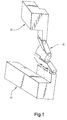
- FIG. 1 shows the bar ends 10 not in alignment such that the ends of the bars either need to be moved into alignment or the connectors need to be adjusted to match the misalignment.
- the multi-plane adjustable connector of the present invention facilitates the electrical connection between the radially adjacent bar ends 10.
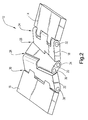
- FIG. 2 shows the multi-plane adjustable connector 12 of the present invention.
- the connector includes opposing end sections 14, 16, which are ultimately secured to the armature bar ends.
- a plurality of interim sections 18, 20, 22 are coupled between the opposing end sections 14, 16.
- the opposing end sections 14, 16 and interim sections 18, 20, 22 are connected in a series as shown in FIG. 2 via a plurality of hinges 24, 26, 28, 30 including a corresponding plurality of hinge pins 32, 34, 36, 38, respectively.
- a preferred configuration of the connector 12 of the invention includes a first connector end section 14 including a first half of a first connector hinge mechanism 24.
- a first interim section 18 includes a second half of the first connector hinge mechanism 24 on one side thereof and a first half of an angled hinge mechanism 26 on an opposite side thereof.
- the angled hinge mechanism 26 is angled relative to the first connector hinge mechanism 24, for example.
- the angled hinge mechanism 26 is preferably configured at an angle of about 15-40° relative to for example an angle of the first connector hinge mechanism 24. The angle depends particularly on a size of the armature bars.
- a second interim section 20 includes a second half of the angled hinge mechanism 26 on one side thereof and a first half of an angled continuation hinge mechanism 28 on an opposite side thereof.
- a third interim section 22 includes a second half of the angled continuation hinge mechanism 28 on one side thereof and a first half of a second connector hinge mechanism 30 on an opposite side thereof.
- the angled continuation hinge mechanism 28 is disposed at an opposing (equal and opposite) angle relative to the angled hinge mechanism 26.
- the second connector end section 16 includes a second half of the second connector hinge mechanism 30.
- first connector end section 14 is coupled with the first interim section 18 via the first connector hinge mechanism 24.
- first interim section 18 is coupled with the second interim section 20 via the angled hinge mechanism 26
- second interim section 20 is coupled with the third interim section 22 via the continuation hinge mechanism 28.
- third interim section 22 is coupled with the second connector end section 16 via the second connector hinge mechanism 30.
- Each hinge mechanism 24, 26, 28, 30 includes respective hinge pins 32, 34, 36, 38, wherein each hinge mechanism is pivotable about the respective hinge pin.
- the hinge pins 32, 34, 36, 38 are close fit pins.
- the connector components are typically constructed such that a flat connector side is opposed to a rounded connector side as shown.
- the first half of the first connector hinge mechanism 24 of the first connector end section 14 is shown with squared or flat ends, while the second half of the first connector hinge 24 on the first interim section 18 is provided with rounded ends.
- each of the respective hinge mechanisms 24, 26, 28, 30 can typically pivot through about 180°.
- the hinge pins 32, 34, 36, 38, the first and second connector end sections 14, 16, and the first, second and third interim sections 18, 20, 22 are formed of copper, although other conducting materials may be suitable provided they can be appropriately brazed or welded. Aluminum is an example of a suitable alternative material. Additionally, the components of the connector 12 including the hinge pins may be pretreated with braze material for the final braze process that would solidify the assembly and attach the assembly to the armature bar ends 10.
- the connector components are typically machined into desired shapes using conventional machining methodologies.
- the components may alternatively be stamped or otherwise constructed, although it is desirable to at least machine the openings for the hinge pins to ensure a close fit.
- the connector 12 of the present invention is shown in FIG. 2 with three interim sections 18, 20, 22 and two angled hinge mechanisms 26, 28.
- the invention is not necessarily meant to be limited to the illustrated construction. Rather, fewer or additional interim sections may be incorporated, and only one or more than two angled hinge mechanisms may also be incorporated.
- the hinges may also have varying constructions including different numbers of fingers, etc.
- the hinge mechanisms are shown with rounded ends facing flat ends, the specific constructions may be varied to suit manufacturing preferences, or alternatively all of the ends may be formed in a rounded construction.
Landscapes
- Engineering & Computer Science (AREA)
- Power Engineering (AREA)
- Manufacture Of Motors, Generators (AREA)
- Windings For Motors And Generators (AREA)
- Insulation, Fastening Of Motor, Generator Windings (AREA)
Abstract
Description
- The present invention relates to a multi-plane electromechanical connector and, more particularly, a multi-plane adjustable connector suited for effecting solid electromechanical connection between two aligned or misaligned radially adjacent armature bar ends contained within air cooled dynamo generators.
- After the installation of armature bars into the stator frame of a generator, two radially adjacent bar ends need to be electrically connected. If the bar ends are not in alignment, either the ends of the bars need to be moved into alignment, or the connectors need to be adjusted to match the misalignment. In some instances, both are required. The process of moving the bar ends, however, puts the bar integrity at risk. Additionally, the modification of connectors is costly and time consuming. Reduction in risk, cost and time in enabling a generator to be back in service are of course of high priority.
- Presently, armature bars are jacked into alignment, which however put the bar insulation in a high fatigue, high potential failure risk situation. Still further, such jacking does not necessarily guarantee alignment. An alternative solution has been to measure the misalignment of each bar connection, then cut and bend solid copper connector plates to accommodate the misalignment. This process, however, could result in more than 100 custom made different connectors, and such a labor intensive process significantly increases costs and cycle time.
- In an exemplary embodiment of the invention, a multi-plane adjustable connector includes a first connector end section including a first half of a first connector hinge mechanism; a first interim section including a second half of the first connector hinge mechanism on one side thereof and a first half of an angled hinge mechanism on an opposite side thereof, the angled hinge mechanism being angled relative to the first connector hinge mechanism; a second interim section including a second half of the angled hinge mechanism on one side thereof and a first half of an angled continuation hinge mechanism on an opposite side thereof; a third interim section including a second half of the angled continuation hinge mechanism on one side thereof and a first half of a second connector hinge mechanism on an opposite side thereof; and a second connector end section including a second half of the second connector hinge mechanism.
- In another exemplary embodiment of the invention, a multi-plane adjustable connector includes opposing end sections positionable in multiple orientations; and a plurality of interim sections coupled between the opposing end sections. The opposing end sections and interim sections are connected in a series via a plurality of hinges, respectively, where at least one of the plurality of hinges is angled relative to others.
- An embodiment of the invention will now be described, by way of example, with reference to the accompanying drawings, in which:
- FIGURE 1 shows two radially adjacent armature bar ends; and
- FIGURE 2 is a perspective view of the multi-plane adjustable connector of the present invention.
-
- As mentioned above, with reference to FIG. 1, after installation of armature bars into the stator frame of a generator, the two radially
adjacent bar ends 10 need to be electrically connected. FIG. 1 shows the bar ends 10 not in alignment such that the ends of the bars either need to be moved into alignment or the connectors need to be adjusted to match the misalignment. The multi-plane adjustable connector of the present invention facilitates the electrical connection between the radiallyadjacent bar ends 10. - FIG. 2 shows the multi-plane
adjustable connector 12 of the present invention. Generally, the connector includesopposing end sections interim sections opposing end sections opposing end sections interim sections hinges hinge pins - A preferred configuration of the
connector 12 of the invention includes a firstconnector end section 14 including a first half of a firstconnector hinge mechanism 24. A firstinterim section 18 includes a second half of the firstconnector hinge mechanism 24 on one side thereof and a first half of anangled hinge mechanism 26 on an opposite side thereof. As shown in FIG. 2, theangled hinge mechanism 26 is angled relative to the firstconnector hinge mechanism 24, for example. Theangled hinge mechanism 26 is preferably configured at an angle of about 15-40° relative to for example an angle of the firstconnector hinge mechanism 24. The angle depends particularly on a size of the armature bars. - A second
interim section 20 includes a second half of theangled hinge mechanism 26 on one side thereof and a first half of an angledcontinuation hinge mechanism 28 on an opposite side thereof. A thirdinterim section 22 includes a second half of the angledcontinuation hinge mechanism 28 on one side thereof and a first half of a secondconnector hinge mechanism 30 on an opposite side thereof. Preferably, the angledcontinuation hinge mechanism 28 is disposed at an opposing (equal and opposite) angle relative to theangled hinge mechanism 26. The secondconnector end section 16 includes a second half of the secondconnector hinge mechanism 30. - As shown, the first
connector end section 14 is coupled with the firstinterim section 18 via the firstconnector hinge mechanism 24. Similarly, the firstinterim section 18 is coupled with the secondinterim section 20 via theangled hinge mechanism 26, and the secondinterim section 20 is coupled with the thirdinterim section 22 via thecontinuation hinge mechanism 28. Finally, the thirdinterim section 22 is coupled with the secondconnector end section 16 via the secondconnector hinge mechanism 30. Eachhinge mechanism respective hinge pins hinge pins - In order to maximize a range of adjustability, the connector components are typically constructed such that a flat connector side is opposed to a rounded connector side as shown. For example, the first half of the first
connector hinge mechanism 24 of the firstconnector end section 14 is shown with squared or flat ends, while the second half of the first connector hinge 24 on the firstinterim section 18 is provided with rounded ends. As a consequence, each of therespective hinge mechanisms - Preferably, the
hinge pins connector end sections interim sections connector 12 including the hinge pins may be pretreated with braze material for the final braze process that would solidify the assembly and attach the assembly to thearmature bar ends 10. - The connector components are typically machined into desired shapes using conventional machining methodologies. The components may alternatively be stamped or otherwise constructed, although it is desirable to at least machine the openings for the hinge pins to ensure a close fit.
- The
connector 12 of the present invention is shown in FIG. 2 with threeinterim sections angled hinge mechanisms - With the connector of the present invention, electrical and mechanical connections of adjacent armature bar ends are facilitated without the need to machine, mold or modify the connectors or the position of the armature bar ends.
- For completeness, various aspects of the invention are now set out in the following numbered clauses:
- 1. A multi-plane adjustable connector comprising:
- a first connector end section (14) including a first half of a first connector hinge mechanism (24);
- a first interim section (18) including a second half of the first connector hinge mechanism on one side thereof and a first half of an angled hinge mechanism (26) on an opposite side thereof, the angled hinge mechanism being angled relative to the first connector hinge mechanism;
- a second interim section (20) including a second half of the angled hinge mechanism on one side thereof and a first half of an angled continuation hinge mechanism (28) on an opposite side thereof;
- a third interim section (22) including a second half of the angled continuation hinge mechanism on one side thereof and a first half of a second connector hinge mechanism 30) on an opposite side thereof; and
- a second connector end section (16) including a second half of the second connector hinge mechanism.
- 2. A multi-plane adjustable connector according to clause 1, wherein the first connector end section (14) is coupled with the first interim section (18) via the first connector hinge mechanism (24); the first interim section is coupled with the second interim section (20) via the angled hinge mechanism (26); the second interim section is coupled with the third interim section (22) via the angled continuation hinge mechanism (28); and the third interim section is coupled with the second connector end section (16) via the second connector hinge mechanism (30).
- 3. A multi-plane adjustable connector according to clause 2, wherein each hinge mechanism (24, 26, 28, 30) comprises a hinge pin (32, 34, 36, 38), wherein each hinge mechanism is pivotable about the respective hinge pin.
- 4. A multi-plane adjustable connector according to clause 3, wherein each hinge mechanism (24, 26, 28, 30) is pivotable through about 180°.
- 5. A multi-plane adjustable connector according to clause 3, wherein the hinge pins (32, 34, 36, 38), the first and second connector end sections (14, 16), and the first, second and third interim sections (18, 20, 22) are formed of copper.
- 6. A multi-plane adjustable connector according to clause 3, wherein the hinge pins (32, 34, 36, 38), the first and second connector end sections (14, 16), and the first, second and third interim sections (18, 20, 22) are pretreated with braze material.
- 7. A multi-plane adjustable connector according to clause 1, wherein the first and second connector end sections (14, 16) and the first, second and third interim sections (18, 20, 22) are formed of copper.
- 8. A multi-plane adjustable connector according to clause 1, wherein the first and second connector end sections (14, 16) and the first, second and third interim sections (18, 20, 22) are pretreated with braze material.
- 9. A multi-plane adjustable connector according to clause 1, wherein the angled hinge mechanism (26) is disposed at an angle of about 15-40° relative to the first connector hinge mechanism (24).
- 10. A multi-plane adjustable connector according to clause 9, wherein the angled continuation hinge mechanism (28) is disposed at an opposing angle relative to the angled hinge mechanism (24).
- 11. A multi-plane adjustable connector comprising:
- a plurality of interim sections (18, 20, 22) coupled between the opposing end sections, wherein the opposing end sections and interim sections are connected in a series via a plurality of hinges (24, 26, 28, 30), respectively, at least one of the plurality of hinges being angled relative to others.
- 12. A multi-plane adjustable connector according to clause 11, wherein the plurality of hinges (24, 26, 28, 30) are secured via a corresponding plurality of hinge pins (32, 34, 36, 38).
- 13. A multi-plane adjustable connector according to
clause 12, wherein each hinge (24, 26, 28, 30) is pivotable through about 180°. - 14. A multi-plane adjustable connector according to
clause 12, wherein the hinge pins (32, 34, 36, 38), the opposing end sections (14, 16) and the plurality of interim sections (18, 20, 22) are formed of copper. - 15. A multi-plane adjustable connector according to
clause 12, wherein the hinge pins (32, 34, 36, 38), the opposing end sections (14, 16) and the plurality of interim sections (18, 20, 22) are pretreated with braze material. - 16. A multi-plane adjustable connector according to clause 11, wherein the opposing end sections (14, 16) and the plurality of interim sections (18, 20, 22) are formed of copper.
- 17. A multi-plane adjustable connector according to clause 11, wherein the opposing end sections (14, 16) and the plurality of interim sections (18, 20, 22) are pretreated with braze material.
- 18. A multi-plane adjustable connector according to clause 11, wherein the angled hinge (26) is disposed at an angle of about 15-40° relative to the other hinges.
- 19. A multi-plane adjustable connector according to clause 11, comprising two angled hinges (26, 28) disposed at opposing angles of about 15-40° relative to the other hinges.
- 20. A method of connecting first and second armature bar ends in a
generator using the multi-plane adjustable connector of
clause 10, the method comprising: - securing one of the opposing end sections (14, 16) to the first armature bar end (10);
- positioning the other of the opposing end sections (14, 16) adjacent the second armature bar end via the plurality of interim sections (18, 20, 22); and securing the other of the opposing end sections to the second armature bar end (10).
-
Claims (10)
- A multi-plane adjustable connector comprising:a first connector end section (14) including a first half of a first connector hinge mechanism (24);a first interim section (18) including a second half of the first connector hinge mechanism on one side thereof and a first half of an angled hinge mechanism (26) on an opposite side thereof, the angled hinge mechanism being angled relative to the first connector hinge mechanism;a second interim section (20) including a second half of the angled hinge mechanism on one side thereof and a first half of an angled continuation hinge mechanism (28) on an opposite side thereof;a third interim section (22) including a second half of the angled continuation hinge mechanism on one side thereof and a first half of a second connector hinge mechanism 30) on an opposite side thereof; anda second connector end section (16) including a second half of the second connector hinge mechanism.
- A multi-plane adjustable connector according to claim 1, wherein the first connector end section (14) is coupled with the first interim section (18) via the first connector hinge mechanism (24); the first interim section is coupled with the second interim section (20) via the angled hinge mechanism (26); the second interim section is coupled with the third interim section (22) via the angled continuation hinge mechanism (28); and the third interim section is coupled with the second connector end section (16) via the second connector hinge mechanism (30).
- A multi-plane adjustable connector according to claim 2, wherein each hinge mechanism (24, 26, 28, 30) comprises a hinge pin (32, 34, 36, 38), wherein each hinge mechanism is pivotable about the respective hinge pin.
- A multi-plane adjustable connector according to claim 3, wherein each hinge mechanism (24, 26, 28, 30) is pivotable through about 180°.
- A multi-plane adjustable connector according to claim 1, wherein the angled hinge mechanism (26) is disposed at an angle of about 15-40° relative to the first connector hinge mechanism (24).
- A multi-plane adjustable connector comprising:a plurality of interim sections (18, 20, 22) coupled between the opposing end sections, wherein the opposing end sections and interim sections are connected in a series via a plurality of hinges (24, 26, 28, 30), respectively, at least one of the plurality of hinges being angled relative to others.
- A multi-plane adjustable connector according to claim 6, wherein the plurality of hinges (24, 26, 28, 30) are secured via a corresponding plurality of hinge pins (32, 34, 36, 38).
- A multi-plane adjustable connector according to claim 7, wherein each hinge (24, 26, 28, 30) is pivotable through about 180°.
- A multi-plane adjustable connector according to claim 6, wherein the angled hinge (26) is disposed at an angle of about 15-40° relative to the other hinges.
- A method of connecting first and second armature bar ends in a generator using the multi-plane adjustable connector of claim 10, the method comprising:securing one of the opposing end sections (14, 16) to the first armature bar end (10);positioning the other of the opposing end sections (14, 16) adjacent the second armature bar end via the plurality of interim sections (18, 20, 22); and securing the other of the opposing end sections to the second armature bar end (10).
Applications Claiming Priority (2)
| Application Number | Priority Date | Filing Date | Title |
|---|---|---|---|
| US10/322,442 US6722892B1 (en) | 2002-12-19 | 2002-12-19 | Multi-plane adjustable connector |
| US322442 | 2002-12-19 |
Publications (2)
| Publication Number | Publication Date |
|---|---|
| EP1432084A1 true EP1432084A1 (en) | 2004-06-23 |
| EP1432084B1 EP1432084B1 (en) | 2006-12-13 |
Family
ID=32069494
Family Applications (1)
| Application Number | Title | Priority Date | Filing Date |
|---|---|---|---|
| EP03257924A Expired - Lifetime EP1432084B1 (en) | 2002-12-19 | 2003-12-16 | Multi-plane adjustable connector |
Country Status (4)
| Country | Link |
|---|---|
| US (1) | US6722892B1 (en) |
| EP (1) | EP1432084B1 (en) |
| JP (1) | JP3972990B2 (en) |
| DE (1) | DE60310356T2 (en) |
Cited By (1)
| Publication number | Priority date | Publication date | Assignee | Title |
|---|---|---|---|---|
| CN107112702A (en) * | 2014-12-31 | 2017-08-29 | 深圳市大富精工有限公司 | A conductive loose-leaf |
Families Citing this family (8)
| Publication number | Priority date | Publication date | Assignee | Title |
|---|---|---|---|---|
| US6991467B1 (en) * | 2004-09-28 | 2006-01-31 | Union Power Information Ind. Co., Ltd. | Adjustable electric adaptor |
| US7128615B1 (en) * | 2006-04-26 | 2006-10-31 | Sheng-Hsin Liao | Connector assembly |
| US7766660B1 (en) * | 2009-09-04 | 2010-08-03 | Linshiung Enterprise Co., Ltd. | Electrical connector housing |
| US8737064B2 (en) * | 2010-01-12 | 2014-05-27 | Microsoft Corporation | Electronic device stand |
| US8753128B2 (en) * | 2011-03-31 | 2014-06-17 | Motorola Mobility Llc | Method and apparatus for coupling portable communication devices |
| CN105337130A (en) * | 2014-06-05 | 2016-02-17 | 富士康(昆山)电脑接插件有限公司 | Multifunctional cable connector assembly |
| DE102015116490A1 (en) * | 2014-11-19 | 2016-05-19 | Rosenberger Hochfrequenztechnik Gmbh & Co. Kg | Magnetic connection device |
| EP3460957A1 (en) * | 2017-09-25 | 2019-03-27 | Siemens Aktiengesellschaft | Bar winding for a stator of an electrically rotating machine |
Citations (2)
| Publication number | Priority date | Publication date | Assignee | Title |
|---|---|---|---|---|
| US3614493A (en) * | 1970-01-29 | 1971-10-19 | Gen Electric | Universal liquid-cooled connection assembly |
| FR2549654A1 (en) * | 1983-07-21 | 1985-01-25 | Alsthom Atlantique | Electrical junction device between stator bars of a water-cooled turbo-alternator, and method of mounting this device. |
Family Cites Families (10)
| Publication number | Priority date | Publication date | Assignee | Title |
|---|---|---|---|---|
| US3219750A (en) * | 1961-11-29 | 1965-11-23 | Adamson Alliance Company Ltd | Electrical power supply connection assemblies for moving machinery |
| US4237336A (en) * | 1978-01-16 | 1980-12-02 | Kostjukov Nikolai S | Device for passing electrical and power installation conductors through protective shell separating clean zone from contaminated one and method of assembling same |
| JPS585222U (en) * | 1981-07-02 | 1983-01-13 | 三菱電機株式会社 | Current relay device for superconducting equipment |
| US5267866A (en) * | 1991-12-17 | 1993-12-07 | Xerox Corporation | Flexible electrical interconnect |
| US6326547B1 (en) * | 1999-11-02 | 2001-12-04 | Compaq Computer Corporation | Cable management system |
| US6331745B2 (en) | 1999-11-22 | 2001-12-18 | General Electric Company | Adjustable generator stator slot wedge system |
| US6218759B1 (en) | 1999-12-02 | 2001-04-17 | General Electric Co. | Generator core end support ring for applying a radial outward force to armature windings outboard of stator core slot dovetails |
| US6293803B1 (en) * | 2000-02-09 | 2001-09-25 | Trw Inc. | Zee electrical interconnect |
| US6347968B1 (en) | 2000-12-21 | 2002-02-19 | General Electric Company | Apparatus and methods for providing an electrical connection between a bore copper and field windings of a dynamoelectric machine |
| US6453540B1 (en) | 2000-12-22 | 2002-09-24 | General Electric Company | Tool for the installation of a terminal stud adapter in a generator rotor and methods therefor |
-
2002
- 2002-12-19 US US10/322,442 patent/US6722892B1/en not_active Expired - Fee Related
-
2003
- 2003-12-16 EP EP03257924A patent/EP1432084B1/en not_active Expired - Lifetime
- 2003-12-16 DE DE60310356T patent/DE60310356T2/en not_active Expired - Lifetime
- 2003-12-18 JP JP2003420292A patent/JP3972990B2/en not_active Expired - Fee Related
Patent Citations (2)
| Publication number | Priority date | Publication date | Assignee | Title |
|---|---|---|---|---|
| US3614493A (en) * | 1970-01-29 | 1971-10-19 | Gen Electric | Universal liquid-cooled connection assembly |
| FR2549654A1 (en) * | 1983-07-21 | 1985-01-25 | Alsthom Atlantique | Electrical junction device between stator bars of a water-cooled turbo-alternator, and method of mounting this device. |
Cited By (1)
| Publication number | Priority date | Publication date | Assignee | Title |
|---|---|---|---|---|
| CN107112702A (en) * | 2014-12-31 | 2017-08-29 | 深圳市大富精工有限公司 | A conductive loose-leaf |
Also Published As
| Publication number | Publication date |
|---|---|
| DE60310356T2 (en) | 2007-10-11 |
| JP2004201496A (en) | 2004-07-15 |
| JP3972990B2 (en) | 2007-09-05 |
| DE60310356D1 (en) | 2007-01-25 |
| EP1432084B1 (en) | 2006-12-13 |
| US6722892B1 (en) | 2004-04-20 |
Similar Documents
| Publication | Publication Date | Title |
|---|---|---|
| CA2191165C (en) | Endhead joint for stator bars | |
| US6722892B1 (en) | Multi-plane adjustable connector | |
| US4642885A (en) | Method of assembling a stator | |
| US7591660B1 (en) | Bi-directional lug connection and method | |
| JPH02184233A (en) | Generator and generator stator coil connection method | |
| JP2003037920A (en) | Electrical connection box | |
| CN1012834B (en) | A device for securing a turbine casing | |
| CA2285103A1 (en) | Electrical wiring frame | |
| WO2020072229A1 (en) | Splice plate for connecting cable bus enclosures | |
| US20130035005A1 (en) | High current contact and corresponding method for producing a high current contact assembly | |
| JP2003033000A5 (en) | ||
| DE69109569T2 (en) | Brush holder for electrical collector machine. | |
| EP0837542A1 (en) | Connector assembly for the windings of a stator of an electric motor | |
| US6710497B2 (en) | Apparatus and method for a field winding assembly mountable on a rotor in a synchronous machine | |
| WO2024108557A1 (en) | Apparatuses and methods for connecting-together pole tabs of electrochemical cells in a stack of such cells | |
| JP3026729B2 (en) | Parts fixing structure of electrical junction box | |
| AU2004240143A1 (en) | Open coil resistance heater with right and left hand installation capability and method of use | |
| JP3330606B2 (en) | Compressor equipment | |
| EP1151511B1 (en) | An electrical cabinet and a frame therefor | |
| EP0867953B1 (en) | Method for forming a battery terminal connector | |
| US20050133679A1 (en) | Supporting device for busbars in cabinets for electrical switchboards | |
| JP2004328841A (en) | Positioning structure between busbars and electrical junction box | |
| WO1998044617A1 (en) | Device for supporting the stator of an electric machine, especially a turbo generator | |
| JPH08126182A (en) | Structure of bus bar phase converting section | |
| EP3891869A1 (en) | Bolting connection for conductors of a generator |
Legal Events
| Date | Code | Title | Description |
|---|---|---|---|
| PUAI | Public reference made under article 153(3) epc to a published international application that has entered the european phase |
Free format text: ORIGINAL CODE: 0009012 |
|
| AK | Designated contracting states |
Kind code of ref document: A1 Designated state(s): AT BE BG CH CY CZ DE DK EE ES FI FR GB GR HU IE IT LI LU MC NL PT RO SE SI SK TR |
|
| AX | Request for extension of the european patent |
Extension state: AL LT LV MK |
|
| 17P | Request for examination filed |
Effective date: 20041223 |
|
| AKX | Designation fees paid |
Designated state(s): CH DE GB LI |
|
| 17Q | First examination report despatched |
Effective date: 20050408 |
|
| GRAP | Despatch of communication of intention to grant a patent |
Free format text: ORIGINAL CODE: EPIDOSNIGR1 |
|
| GRAS | Grant fee paid |
Free format text: ORIGINAL CODE: EPIDOSNIGR3 |
|
| GRAA | (expected) grant |
Free format text: ORIGINAL CODE: 0009210 |
|
| AK | Designated contracting states |
Kind code of ref document: B1 Designated state(s): CH DE GB LI |
|
| REG | Reference to a national code |
Ref country code: GB Ref legal event code: FG4D |
|
| REG | Reference to a national code |
Ref country code: CH Ref legal event code: EP Ref country code: CH Ref legal event code: NV Representative=s name: SERVOPATENT GMBH |
|
| REF | Corresponds to: |
Ref document number: 60310356 Country of ref document: DE Date of ref document: 20070125 Kind code of ref document: P |
|
| PLBE | No opposition filed within time limit |
Free format text: ORIGINAL CODE: 0009261 |
|
| STAA | Information on the status of an ep patent application or granted ep patent |
Free format text: STATUS: NO OPPOSITION FILED WITHIN TIME LIMIT |
|
| 26N | No opposition filed |
Effective date: 20070914 |
|
| REG | Reference to a national code |
Ref country code: CH Ref legal event code: PFA Owner name: GENERAL ELECTRIC COMPANY Free format text: GENERAL ELECTRIC COMPANY#1 RIVER ROAD#SCHENECTADY, NY 12345 (US) -TRANSFER TO- GENERAL ELECTRIC COMPANY#1 RIVER ROAD#SCHENECTADY, NY 12345 (US) |
|
| PGFP | Annual fee paid to national office [announced via postgrant information from national office to epo] |
Ref country code: CH Payment date: 20131230 Year of fee payment: 11 Ref country code: DE Payment date: 20131230 Year of fee payment: 11 Ref country code: GB Payment date: 20131227 Year of fee payment: 11 |
|
| REG | Reference to a national code |
Ref country code: DE Ref legal event code: R119 Ref document number: 60310356 Country of ref document: DE |
|
| REG | Reference to a national code |
Ref country code: CH Ref legal event code: PL |
|
| GBPC | Gb: european patent ceased through non-payment of renewal fee |
Effective date: 20141216 |
|
| PG25 | Lapsed in a contracting state [announced via postgrant information from national office to epo] |
Ref country code: GB Free format text: LAPSE BECAUSE OF NON-PAYMENT OF DUE FEES Effective date: 20141216 Ref country code: DE Free format text: LAPSE BECAUSE OF NON-PAYMENT OF DUE FEES Effective date: 20150701 Ref country code: CH Free format text: LAPSE BECAUSE OF NON-PAYMENT OF DUE FEES Effective date: 20141231 Ref country code: LI Free format text: LAPSE BECAUSE OF NON-PAYMENT OF DUE FEES Effective date: 20141231 |