EP1432053A1 - Battery pack and thermostat used for it - Google Patents
Battery pack and thermostat used for it Download PDFInfo
- Publication number
- EP1432053A1 EP1432053A1 EP02760686A EP02760686A EP1432053A1 EP 1432053 A1 EP1432053 A1 EP 1432053A1 EP 02760686 A EP02760686 A EP 02760686A EP 02760686 A EP02760686 A EP 02760686A EP 1432053 A1 EP1432053 A1 EP 1432053A1
- Authority
- EP
- European Patent Office
- Prior art keywords
- electrode
- thermostat
- circuit board
- casing
- battery pack
- Prior art date
- Legal status (The legal status is an assumption and is not a legal conclusion. Google has not performed a legal analysis and makes no representation as to the accuracy of the status listed.)
- Granted
Links
Images


Classifications
-
- H—ELECTRICITY
- H01—ELECTRIC ELEMENTS
- H01M—PROCESSES OR MEANS, e.g. BATTERIES, FOR THE DIRECT CONVERSION OF CHEMICAL ENERGY INTO ELECTRICAL ENERGY
- H01M10/00—Secondary cells; Manufacture thereof
- H01M10/42—Methods or arrangements for servicing or maintenance of secondary cells or secondary half-cells
- H01M10/48—Accumulators combined with arrangements for measuring, testing or indicating the condition of cells, e.g. the level or density of the electrolyte
- H01M10/486—Accumulators combined with arrangements for measuring, testing or indicating the condition of cells, e.g. the level or density of the electrolyte for measuring temperature
-
- H—ELECTRICITY
- H01—ELECTRIC ELEMENTS
- H01M—PROCESSES OR MEANS, e.g. BATTERIES, FOR THE DIRECT CONVERSION OF CHEMICAL ENERGY INTO ELECTRICAL ENERGY
- H01M50/00—Constructional details or processes of manufacture of the non-active parts of electrochemical cells other than fuel cells, e.g. hybrid cells
- H01M50/20—Mountings; Secondary casings or frames; Racks, modules or packs; Suspension devices; Shock absorbers; Transport or carrying devices; Holders
-
- H—ELECTRICITY
- H01—ELECTRIC ELEMENTS
- H01H—ELECTRIC SWITCHES; RELAYS; SELECTORS; EMERGENCY PROTECTIVE DEVICES
- H01H37/00—Thermally-actuated switches
- H01H37/02—Details
- H01H37/04—Bases; Housings; Mountings
- H01H37/043—Mountings on controlled apparatus
-
- H—ELECTRICITY
- H01—ELECTRIC ELEMENTS
- H01M—PROCESSES OR MEANS, e.g. BATTERIES, FOR THE DIRECT CONVERSION OF CHEMICAL ENERGY INTO ELECTRICAL ENERGY
- H01M10/00—Secondary cells; Manufacture thereof
- H01M10/42—Methods or arrangements for servicing or maintenance of secondary cells or secondary half-cells
- H01M10/425—Structural combination with electronic components, e.g. electronic circuits integrated to the outside of the casing
- H01M10/4257—Smart batteries, e.g. electronic circuits inside the housing of the cells or batteries
-
- H—ELECTRICITY
- H01—ELECTRIC ELEMENTS
- H01M—PROCESSES OR MEANS, e.g. BATTERIES, FOR THE DIRECT CONVERSION OF CHEMICAL ENERGY INTO ELECTRICAL ENERGY
- H01M10/00—Secondary cells; Manufacture thereof
- H01M10/60—Heating or cooling; Temperature control
- H01M10/61—Types of temperature control
- H01M10/613—Cooling or keeping cold
-
- H—ELECTRICITY
- H01—ELECTRIC ELEMENTS
- H01M—PROCESSES OR MEANS, e.g. BATTERIES, FOR THE DIRECT CONVERSION OF CHEMICAL ENERGY INTO ELECTRICAL ENERGY
- H01M10/00—Secondary cells; Manufacture thereof
- H01M10/60—Heating or cooling; Temperature control
- H01M10/62—Heating or cooling; Temperature control specially adapted for specific applications
- H01M10/623—Portable devices, e.g. mobile telephones, cameras or pacemakers
-
- H—ELECTRICITY
- H01—ELECTRIC ELEMENTS
- H01M—PROCESSES OR MEANS, e.g. BATTERIES, FOR THE DIRECT CONVERSION OF CHEMICAL ENERGY INTO ELECTRICAL ENERGY
- H01M10/00—Secondary cells; Manufacture thereof
- H01M10/60—Heating or cooling; Temperature control
- H01M10/63—Control systems
- H01M10/637—Control systems characterised by the use of reversible temperature-sensitive devices, e.g. NTC, PTC or bimetal devices; characterised by control of the internal current flowing through the cells, e.g. by switching
-
- H—ELECTRICITY
- H01—ELECTRIC ELEMENTS
- H01M—PROCESSES OR MEANS, e.g. BATTERIES, FOR THE DIRECT CONVERSION OF CHEMICAL ENERGY INTO ELECTRICAL ENERGY
- H01M50/00—Constructional details or processes of manufacture of the non-active parts of electrochemical cells other than fuel cells, e.g. hybrid cells
- H01M50/20—Mountings; Secondary casings or frames; Racks, modules or packs; Suspension devices; Shock absorbers; Transport or carrying devices; Holders
- H01M50/204—Racks, modules or packs for multiple batteries or multiple cells
- H01M50/207—Racks, modules or packs for multiple batteries or multiple cells characterised by their shape
- H01M50/209—Racks, modules or packs for multiple batteries or multiple cells characterised by their shape adapted for prismatic or rectangular cells
-
- H—ELECTRICITY
- H01—ELECTRIC ELEMENTS
- H01M—PROCESSES OR MEANS, e.g. BATTERIES, FOR THE DIRECT CONVERSION OF CHEMICAL ENERGY INTO ELECTRICAL ENERGY
- H01M50/00—Constructional details or processes of manufacture of the non-active parts of electrochemical cells other than fuel cells, e.g. hybrid cells
- H01M50/20—Mountings; Secondary casings or frames; Racks, modules or packs; Suspension devices; Shock absorbers; Transport or carrying devices; Holders
- H01M50/218—Mountings; Secondary casings or frames; Racks, modules or packs; Suspension devices; Shock absorbers; Transport or carrying devices; Holders characterised by the material
- H01M50/22—Mountings; Secondary casings or frames; Racks, modules or packs; Suspension devices; Shock absorbers; Transport or carrying devices; Holders characterised by the material of the casings or racks
- H01M50/222—Inorganic material
- H01M50/224—Metals
-
- H—ELECTRICITY
- H01—ELECTRIC ELEMENTS
- H01M—PROCESSES OR MEANS, e.g. BATTERIES, FOR THE DIRECT CONVERSION OF CHEMICAL ENERGY INTO ELECTRICAL ENERGY
- H01M50/00—Constructional details or processes of manufacture of the non-active parts of electrochemical cells other than fuel cells, e.g. hybrid cells
- H01M50/20—Mountings; Secondary casings or frames; Racks, modules or packs; Suspension devices; Shock absorbers; Transport or carrying devices; Holders
- H01M50/271—Lids or covers for the racks or secondary casings
- H01M50/273—Lids or covers for the racks or secondary casings characterised by the material
- H01M50/278—Organic material
-
- H—ELECTRICITY
- H05—ELECTRIC TECHNIQUES NOT OTHERWISE PROVIDED FOR
- H05K—PRINTED CIRCUITS; CASINGS OR CONSTRUCTIONAL DETAILS OF ELECTRIC APPARATUS; MANUFACTURE OF ASSEMBLAGES OF ELECTRICAL COMPONENTS
- H05K1/00—Printed circuits
- H05K1/02—Details
- H05K1/0201—Thermal arrangements, e.g. for cooling, heating or preventing overheating
-
- H—ELECTRICITY
- H05—ELECTRIC TECHNIQUES NOT OTHERWISE PROVIDED FOR
- H05K—PRINTED CIRCUITS; CASINGS OR CONSTRUCTIONAL DETAILS OF ELECTRIC APPARATUS; MANUFACTURE OF ASSEMBLAGES OF ELECTRICAL COMPONENTS
- H05K1/00—Printed circuits
- H05K1/18—Printed circuits structurally associated with non-printed electric components
- H05K1/181—Printed circuits structurally associated with non-printed electric components associated with surface mounted components
-
- H—ELECTRICITY
- H01—ELECTRIC ELEMENTS
- H01H—ELECTRIC SWITCHES; RELAYS; SELECTORS; EMERGENCY PROTECTIVE DEVICES
- H01H1/00—Contacts
- H01H1/58—Electric connections to or between contacts; Terminals
- H01H2001/5877—Electric connections to or between contacts; Terminals with provisions for direct mounting on a battery pole
-
- H—ELECTRICITY
- H01—ELECTRIC ELEMENTS
- H01H—ELECTRIC SWITCHES; RELAYS; SELECTORS; EMERGENCY PROTECTIVE DEVICES
- H01H1/00—Contacts
- H01H1/58—Electric connections to or between contacts; Terminals
- H01H2001/5888—Terminals of surface mounted devices [SMD]
-
- H—ELECTRICITY
- H01—ELECTRIC ELEMENTS
- H01M—PROCESSES OR MEANS, e.g. BATTERIES, FOR THE DIRECT CONVERSION OF CHEMICAL ENERGY INTO ELECTRICAL ENERGY
- H01M2200/00—Safety devices for primary or secondary batteries
- H01M2200/10—Temperature sensitive devices
-
- Y—GENERAL TAGGING OF NEW TECHNOLOGICAL DEVELOPMENTS; GENERAL TAGGING OF CROSS-SECTIONAL TECHNOLOGIES SPANNING OVER SEVERAL SECTIONS OF THE IPC; TECHNICAL SUBJECTS COVERED BY FORMER USPC CROSS-REFERENCE ART COLLECTIONS [XRACs] AND DIGESTS
- Y02—TECHNOLOGIES OR APPLICATIONS FOR MITIGATION OR ADAPTATION AGAINST CLIMATE CHANGE
- Y02E—REDUCTION OF GREENHOUSE GAS [GHG] EMISSIONS, RELATED TO ENERGY GENERATION, TRANSMISSION OR DISTRIBUTION
- Y02E60/00—Enabling technologies; Technologies with a potential or indirect contribution to GHG emissions mitigation
- Y02E60/10—Energy storage using batteries
-
- Y—GENERAL TAGGING OF NEW TECHNOLOGICAL DEVELOPMENTS; GENERAL TAGGING OF CROSS-SECTIONAL TECHNOLOGIES SPANNING OVER SEVERAL SECTIONS OF THE IPC; TECHNICAL SUBJECTS COVERED BY FORMER USPC CROSS-REFERENCE ART COLLECTIONS [XRACs] AND DIGESTS
- Y02—TECHNOLOGIES OR APPLICATIONS FOR MITIGATION OR ADAPTATION AGAINST CLIMATE CHANGE
- Y02P—CLIMATE CHANGE MITIGATION TECHNOLOGIES IN THE PRODUCTION OR PROCESSING OF GOODS
- Y02P70/00—Climate change mitigation technologies in the production process for final industrial or consumer products
- Y02P70/50—Manufacturing or production processes characterised by the final manufactured product
Definitions
- the present invention relates to a battery pack and a thermostat used therefor, and particularly to a technical field of a battery pack in which a battery cell and a circuit board for protecting the battery cell are housed in a casing, and a thermostat used therefor.
- a battery pack for example a battery pack in which a lithium ion secondary battery cell is housed in a casing.
- a battery pack is used as a power supply for a communication apparatus such as a portable telephone, for example.
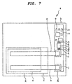
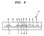
- FIG. 7 and FIG. 8 schematically show an example of a conventional battery pack.
- a battery pack “a” is formed by housing a battery cell “c” such as a lithium ion secondary battery cell or the like and a circuit board “d” for protecting the battery cell “c” within a casing "b".
- the battery cell “c” is formed by sealing a battery main body portion “e” with a covering (aluminum laminate material) "f” made of a polymer material.
- a first electrode lead "g” connected to a positive electrode of the battery cell “c” and a second electrode lead “h” connected to a negative electrode of the battery cell “c” are projected from the battery cell “c” in the same direction in a state of being separated from each other at a distance in a direction of width of the battery cell "c".
- the circuit board "d” is provided with a first electrode connecting portion "i", a second electrode connecting portion "j", and thermostat connecting portions "k” and "k". An end portion of the first electrode lead “g” projected from the battery cell “c” is connected to the first electrode connecting portion "i”. An end portion of the second electrode lead "h” projected from the battery cell “c” is connected to the second electrode connecting portion "j".
- the circuit board “d” has a thermostat “1” mounted thereon to prevent excessive increase in temperature within the casing "b".
- the thermostat “1” has a casing portion “m” formed of a nonconductive material, and a pair of electrode portions “n” and “n” projected from the casing portion “m” in directions opposite to each other.
- the electrode portions “n” and “n” are joined to the thermostat connecting portions “k” and “k”, respectively, of the circuit board “d” by soldering, for example.
- the thermostat “l” is situated immediately beside the first electrode connecting portion "i”.
- the circuit board “d” has required chip parts “o”, “o”, ... such as ICs (Integrated Circuits), FETs (Field Effect Transistors), and the like mounted thereon.
- the thermostat "l” needs to be mounted at a position different from positions of the first electrode connecting portion “i” and the second electrode connecting portion “j” of the circuit board “d". Accordingly a space exclusively for mounting the thermostat “l” on the circuit board “d” is required, so that with an increase in size of the circuit board "d", the battery pack "a" becomes larger.
- a battery pack including a thermostat having a casing portion formed of a nonconductive material, a first electrode portion disposed at one surface of the casing portion, and a second electrode portion disposed at another surface opposite to the one surface of the casing portion, wherein one electrode lead is connected to one electrode connecting portion of a circuit board; another electrode lead is connected to the first electrode portion of the thermostat; and the second electrode portion of the thermostat is connected to another electrode connecting portion of the circuit board.
- a thermostat for use in a battery pack.
- the thermostat includes a casing portion formed of a nonconductive material, a first electrode portion disposed at one surface of the casing portion and connected with another electrode lead, and a second electrode portion disposed at another surface opposite to the one surface of the casing portion and connected with another electrode connecting portion of the circuit board.
- one electrode portion of the thermostat functions as an electrode connecting portion to which one electrode lead is connected.
- a battery pack 1 is formed by housing a battery cell 3 such as a lithium ion secondary battery cell or the like and a circuit board 4 for protecting the battery cell 3 within a casing 2 of a flat and substantially rectangular shape (see FIG. 1).
- the battery cell 3 is formed by sealing a battery main body portion 3a with a covering 3b made of a polymer material.
- the first electrode lead 5 is formed of an aluminum material
- the second electrode lead 6 is formed of a nickel material.
- the circuit board 4 is formed in a rectangular shape that is long in the direction of width of the battery cell 3.
- the circuit board 4 has a first electrode connecting portion 7 and a second electrode connecting portion 8 provided at both respective end portions in a direction of length of the circuit board 4.
- An end portion of the first electrode lead 5 projected from the battery cell 3 is connected to the first electrode connecting portion 7 by welding, for example (see FIG. 1 and FIG. 2).
- the circuit board 4 has a thermostat 9 mounted thereon to prevent excessive increase in temperature within the casing 2 (see FIG. 1 and FIG. 2).
- the thermostat 9 is formed in substantially a shape of a rectangular parallelepiped.
- the thermostat 9 has a casing portion 10 formed of a nonconductive material, a first conductive portion 11 formed by a plate-shaped metallic material, and a second conductive portion 12 similarly formed by a plate-shaped metallic material (see FIGS. 3 to 5).
- the casing portion 10 has a disposing recess portion 10b that opens on a side of one surface 10a (see FIG. 4).
- the first conductive portion 11 has a first electrode portion 13, a movable piece portion 14, and auxiliary electrode portions 15 and 15 (see FIGS. 3 to 5).
- the first electrode portion 13 is disposed on the side of one surface 10a so as to cover the disposing recess portion 10b of the casing portion 10.
- a portion (a portion enclosed by alternate long and short dashed lines in FIG. 3) excluding a peripheral portion of the first electrode portion 13 is formed as a welding portion area 13a.
- the movable piece portion 14 is formed by bending over from one edge 13b of the first electrode portion 13.
- the movable piece portion 14 is capable of elastic displacement with respect to the first electrode portion 13.
- the movable piece portion 14 has a contact portion 14a provided at an end portion thereof, and the contact portion 14a is projected in a direction opposite to a side where the first electrode portion 13 is situated.
- the auxiliary electrode portions 15 and 15 are respectively projected from both side edges orthogonal to the one edge 13b of the first electrode portion 13 in a direction orthogonal to the first electrode portion 13.
- the auxiliary electrode portions 15 and 15 have end portions formed as connecting portions 15a and 15a.
- the connecting portions 15a and 15a are bent perpendicularly to be parallel with the first electrode portion 13, and is situated so as to be opposed to a part of another surface 10c of the casing portion 10.
- the surface 10c is opposite to the one surface 10a of the casing portion 10 (see FIG. 4 and FIG. 5).
- the second conductive portion 12 includes a base portion 16, connecting portions 17 and 17, and second electrode portions 18 and 18 (see FIG. 4 and FIG. 5).
- the base portion 16 is buried on an opposite side from the first electrode portion 13 in parallel with the first electrode portion 13 with the movable piece portion 14 interposed between the first electrode portion 13 and the base portion 16 within the casing portion 10.
- a contact portion 16a projecting to a side of the contact portion 14a is provided at a position opposed to the contact portion 14a of the movable piece portion 14.
- the connecting portions 17 and 17 are formed by being bent perpendicularly from both edges of the base portion 16 in a direction opposite to a side where the first conductive portion 11 is situated.
- the second electrode portions 18 and 18 are formed by being bent perpendicularly from both edges of the connecting portions 17 and 17, and are situated so as to be opposed to a part of the other surface 10c of the casing portion 10 (see FIG. 4 and FIG. 5).
- the second electrode portions 18 and 18 are situated so as to be separated from each other at a distance in a direction orthogonal to a direction to connect the connecting portions 15a and 15a of the auxiliary electrode portions 15 and 15 with each other (see FIG. 5).
- the second electrode portions 18 and 18 and the auxiliary electrode portions 15 and 15 of the thermostat 9 are disposed inside an outline of the other surface 10c of the casing portion 10 (see FIG. 5).
- a bimetallic disk 19 is disposed between the movable piece portion 14 of the first conductive portion 11 and the base portion 16 of the second conductive portion 12 within the casing portion 10 (see FIG. 4).
- the bimetallic disk 19 has one end portion buried in the casing portion 10, and another end portion situated so as to correspond to a position near an end of the movable piece portion 14.
- the bimetallic disk 19 When due to generation of heat from an outside or the like of the battery cell 3 and the battery pack 1, the temperature within the casing 2 increases and reaches a predetermined temperature, the bimetallic disk 19 is bent in a direction to approach the movable piece portion 14, and presses the movable piece portion 14 in a direction to approach the first electrode portion 13, so that the contact portion 14a of the movable piece portion 14 and the contact portion 16a of the base portion 16 in contact with each other are separated from each other.
- the first conductive portion 11 and the second conductive portion 12 are electrically disconnected from each other to prevent excessive increase in temperature within the casing 2.
- the circuit board 4 has required chip parts 20, 20, ... such as ICs, FETs, and the like mounted thereon at a position between the first electrode connecting portion 7 and the second electrode connecting portion 8 (see FIG. 1 and FIG. 2).
- the second electrode portions 18 and 18 of the thermostat 9 are connected to the second electrode connecting portion 8 of the circuit board 4 (see FIG. 1 and FIG. 2).
- the second electrode portions 18 and 18 are connected to the second electrode connecting portion 8 by so-called reflow soldering performed by melting soldering paste by a hot air, infrared rays, or the like at the same time as the other chip parts 20, 20, ..., for example.
- the auxiliary electrode portions 15 and 15 of the thermostat 9 are intended to enable use of the thermostat 9 even in a conventional battery pack by connecting the connecting portions 15a and 15a of the auxiliary electrode portions 15 and 15 separate from the second electrode portions 18 and 18 to a thermostat connecting portion of a circuit board used in the conventional battery pack.
- the battery pack 1 uses the thermostat 9 having the first electrode portion 13 disposed in the one surface 10a of the casing portion 10 and the second electrode portions 18 and 18 disposed at the other surface 10c of the casing portion 10.
- the second electrode lead 6 projected from the battery main body portion 3a is connected to the first electrode portion 13, and the second electrode portions 18 and 18 are connected to the second electrode connecting portion 8 of the circuit board 4.
- the battery pack 1 eliminates the need for providing a portion exclusively for connecting the thermostat 9 on the circuit board 4 in addition to a portion for connecting each of the first electrode lead 5 and the second electrode lead 6. It is therefore possible to reduce components of the circuit board 4 and simplify a configuration of the circuit board 4.
- the battery pack 1 can be miniaturized.
- the second electrode portions 18 and 18 of the thermostat 9 are disposed inside the outline of the other surface 10c of the casing portion 10 as described above, a disposing space for disposing the thermostat 9 on the circuit board 4 can be further reduced, thus further miniaturizing the battery pack 1.
- first electrode lead 5 is connected to the first electrode connecting portion 7 of the circuit board 4 and the second electrode lead 6 is connected to the first electrode portion 13 of the thermostat 9; conversely, however, the second electrode lead 6 may be connected to the first electrode connecting portion 7 of the circuit board 4 and the first electrode lead 5 may be connected to the first electrode portion 13 of the thermostat 9.
- the present invention is applicable to a battery pack 1A housing a battery cell 3A formed by disposing required parts within a battery can 21 formed of an aluminum material, as shown in FIG. 6.
- one end portion of a first connecting lead 22 provided as a first electrode lead is connected to a positive electrode (battery can 21) of the battery cell 3A, and one end portion of a second connecting lead 23 provided as a second electrode lead is connected to a negative electrode of the battery cell 3A.
- Another end portion of the first connecting lead 22 is connected to a first electrode connecting portion 7 of a circuit board 4, and another end portion of the second connecting lead 23 is connected by welding to a first electrode portion 13 of a thermostat 9 connected to a second electrode connecting portion 8 of the circuit board 4.
- the battery pack 1A also eliminates the need for providing a portion exclusively for connecting the thermostat 9 on the circuit board 4 in addition to a portion for connecting each of the first connecting lead 22 and the second connecting lead 23. It is therefore possible to reduce components of the circuit board 4 and simplify a configuration of the circuit board 4.
- the battery pack 1A can be miniaturized.
- a battery pack according to the present invention in which a battery cell and a circuit board having a pair of electrode connecting portions are housed in a casing and a pair of electrode leads each connected to a positive electrode or a negative electrode of the battery cell is projected from the battery cell includes a thermostat having a casing portion formed of a nonconductive material, a first electrode portion disposed at one surface of the casing portion, and a second electrode portion disposed at another surface opposite to the one surface of the casing portion, wherein one electrode lead is connected to one electrode connecting portion of the circuit board; the other electrode lead is connected to the first electrode portion of the thermostat; and the second electrode portion of the thermostat is connected to the other electrode connecting portion of the circuit board.
- the battery pack can be miniaturized.
- the second electrode portion of the thermostat is disposed inside the outline of the other surface of the casing portion. Therefore a disposing space for disposing the thermostat on the circuit board can be further reduced, thus further miniaturizing the battery pack.
- a thermostat according to the present invention for use in a battery pack in which a battery cell and a circuit board having a pair of electrode connecting portions are housed in a casing and one of a pair of electrode leads each connected to a positive electrode or a negative electrode of the battery cell is connected to one electrode connecting portion of the circuit board includes a casing portion formed of a nonconductive material, a first electrode portion disposed at one surface of the casing portion and connected with the other electrode lead, and a second electrode portion disposed at another surface opposite to the one surface of the casing portion and connected with the other electrode connecting portion of the circuit board.
- the battery pack using the thermostat can be miniaturized.
- the second electrode portion is disposed inside the outline of the other surface of the casing portion. Therefore a disposing space for disposing the thermostat on the circuit board can be further reduced, thus further miniaturizing the battery pack using the thermostat.
Landscapes
- Engineering & Computer Science (AREA)
- Chemical & Material Sciences (AREA)
- Chemical Kinetics & Catalysis (AREA)
- Electrochemistry (AREA)
- General Chemical & Material Sciences (AREA)
- Manufacturing & Machinery (AREA)
- Microelectronics & Electronic Packaging (AREA)
- Automation & Control Theory (AREA)
- Inorganic Chemistry (AREA)
- Life Sciences & Earth Sciences (AREA)
- Biophysics (AREA)
- Battery Mounting, Suspending (AREA)
- Connection Of Batteries Or Terminals (AREA)
- Thermally Actuated Switches (AREA)
- Secondary Cells (AREA)
Abstract
Description
Claims (4)
- A battery pack in which a battery cell and a circuit board having a pair of electrode connecting portions are housed in a casing and a pair of electrode leads each connected to a positive electrode or a negative electrode of the battery cell is projected from the battery cell, said battery pack comprising:a thermostat having a casing portion formed of a nonconductive material, a first electrode portion disposed at one surface of the casing portion, and a second electrode portion disposed at another surface opposite to the one surface of the casing portion;wherein one electrode lead is connected to one electrode connecting portion of the circuit board;the other electrode lead is connected to the first electrode portion of the thermostat; andthe second electrode portion of the thermostat is connected to the other electrode connecting portion of the circuit board.
- The battery pack as claimed in claim 1, wherein:the second electrode portion of said thermostat is disposed inside an outline of the other surface of the casing portion.
- A thermostat for use in a battery pack, in which a battery cell and a circuit board having a pair of electrode connecting portions are housed in a casing and one of a pair of electrode leads each connected to a positive electrode or a negative electrode of the battery cell is connected to one electrode connecting portion of the circuit board, said thermostat comprising:a casing portion formed of a nonconductive material;a first electrode portion disposed at one surface of the casing portion and connected with the other electrode lead; anda second electrode portion disposed at another surface opposite to the one surface of the casing portion and connected with the other electrode connecting portion of said circuit board.
- The thermostat as claimed in claim 3, wherein:said second electrode portion is disposed inside an outline of the other surface of the casing portion.
Applications Claiming Priority (3)
| Application Number | Priority Date | Filing Date | Title |
|---|---|---|---|
| JP2001297425A JP3716773B2 (en) | 2001-09-27 | 2001-09-27 | Battery pack and thermostat used therefor |
| JP2001297425 | 2001-09-27 | ||
| PCT/JP2002/008429 WO2003030280A1 (en) | 2001-09-27 | 2002-08-21 | Battery pack and thermostat used for it |
Publications (3)
| Publication Number | Publication Date |
|---|---|
| EP1432053A1 true EP1432053A1 (en) | 2004-06-23 |
| EP1432053A4 EP1432053A4 (en) | 2007-01-10 |
| EP1432053B1 EP1432053B1 (en) | 2010-11-03 |
Family
ID=19118510
Family Applications (1)
| Application Number | Title | Priority Date | Filing Date |
|---|---|---|---|
| EP20020760686 Expired - Lifetime EP1432053B1 (en) | 2001-09-27 | 2002-08-21 | Battery pack and thermostat used for it |
Country Status (8)
| Country | Link |
|---|---|
| US (1) | US7556884B2 (en) |
| EP (1) | EP1432053B1 (en) |
| JP (1) | JP3716773B2 (en) |
| KR (1) | KR100966030B1 (en) |
| CN (1) | CN1270394C (en) |
| DE (1) | DE60238207D1 (en) |
| TW (1) | TW561639B (en) |
| WO (1) | WO2003030280A1 (en) |
Cited By (2)
| Publication number | Priority date | Publication date | Assignee | Title |
|---|---|---|---|---|
| EP1708553A3 (en) * | 2005-03-28 | 2008-07-23 | Mitsumi Electric Co., Ltd. | Secondary battery protecting module and lead mounting method |
| EP2495794A3 (en) * | 2011-03-02 | 2014-04-09 | Samsung SDI Co., Ltd. | Battery pack |
Families Citing this family (4)
| Publication number | Priority date | Publication date | Assignee | Title |
|---|---|---|---|---|
| US20060011600A1 (en) * | 2004-07-15 | 2006-01-19 | Mitsuhiko Miyazaki | Soldering device with cartridge type battery pack |
| JP4592117B1 (en) * | 2009-12-25 | 2010-12-01 | 株式会社イー・ピー・アイ | Bimetal circuit breaker |
| JP6267528B2 (en) * | 2014-01-30 | 2018-01-24 | ボーンズ株式会社 | Current interrupt device |
| JP6967932B2 (en) * | 2017-10-04 | 2021-11-17 | ボーンズ株式会社 | A breaker and a safety circuit equipped with it. |
Family Cites Families (14)
| Publication number | Priority date | Publication date | Assignee | Title |
|---|---|---|---|---|
| JPH01126032A (en) | 1987-11-11 | 1989-05-18 | Nec Corp | Apd bias circuit |
| JPH01126032U (en) * | 1988-02-22 | 1989-08-29 | ||
| JPH04101373A (en) | 1990-08-17 | 1992-04-02 | Mitsubishi Electric Corp | Connector insertion error preventing circuit |
| JP2545123Y2 (en) * | 1991-02-20 | 1997-08-25 | 三洋電機株式会社 | Battery pack |
| JPH07262977A (en) | 1994-03-22 | 1995-10-13 | Sanyo Electric Co Ltd | Packed battery |
| JPH09106804A (en) * | 1995-10-09 | 1997-04-22 | Wako Denshi Kk | Battery safety device |
| US6083639A (en) * | 1997-08-22 | 2000-07-04 | Duracell Inc. | Current interrupter for electrochemical cells |
| JP3634128B2 (en) | 1997-10-30 | 2005-03-30 | 松下電器産業株式会社 | Battery pack |
| US5844464A (en) | 1997-11-24 | 1998-12-01 | Therm-O-Disc, Incorporated | Thermal switch |
| US6608470B1 (en) * | 1998-01-31 | 2003-08-19 | Motorola, Inc. | Overcharge protection device and methods for lithium based rechargeable batteries |
| JP3630970B2 (en) * | 1998-02-10 | 2005-03-23 | 三洋電機株式会社 | Pack battery |
| JP3579621B2 (en) | 1998-09-11 | 2004-10-20 | 松下電器産業株式会社 | Battery pack |
| US6451474B1 (en) * | 1998-09-11 | 2002-09-17 | Matsushita Electric Industrial Co., Ltd. | Resiliently deformable battery pack |
| JP2000285776A (en) * | 1999-03-31 | 2000-10-13 | Sanyo Electric Co Ltd | Thermostat and battery pack incorporating this thermostat |
-
2001
- 2001-09-27 JP JP2001297425A patent/JP3716773B2/en not_active Expired - Fee Related
-
2002
- 2002-08-21 WO PCT/JP2002/008429 patent/WO2003030280A1/en not_active Ceased
- 2002-08-21 KR KR1020047004444A patent/KR100966030B1/en not_active Expired - Fee Related
- 2002-08-21 CN CNB028187717A patent/CN1270394C/en not_active Expired - Fee Related
- 2002-08-21 US US10/490,374 patent/US7556884B2/en not_active Expired - Fee Related
- 2002-08-21 EP EP20020760686 patent/EP1432053B1/en not_active Expired - Lifetime
- 2002-08-21 DE DE60238207T patent/DE60238207D1/en not_active Expired - Lifetime
- 2002-09-13 TW TW91120990A patent/TW561639B/en active
Cited By (4)
| Publication number | Priority date | Publication date | Assignee | Title |
|---|---|---|---|---|
| EP1708553A3 (en) * | 2005-03-28 | 2008-07-23 | Mitsumi Electric Co., Ltd. | Secondary battery protecting module and lead mounting method |
| US8305768B2 (en) | 2005-03-28 | 2012-11-06 | Mitsumi Electric Co., Ltd. | Secondary battery protecting module and lead mounting method |
| EP2495794A3 (en) * | 2011-03-02 | 2014-04-09 | Samsung SDI Co., Ltd. | Battery pack |
| US9269946B2 (en) | 2011-03-02 | 2016-02-23 | Samsung Sdi Co., Ltd. | Battery pack having protection circuit module |
Also Published As
| Publication number | Publication date |
|---|---|
| TW561639B (en) | 2003-11-11 |
| JP2003109560A (en) | 2003-04-11 |
| KR100966030B1 (en) | 2010-06-25 |
| US7556884B2 (en) | 2009-07-07 |
| US20040247950A1 (en) | 2004-12-09 |
| EP1432053B1 (en) | 2010-11-03 |
| JP3716773B2 (en) | 2005-11-16 |
| CN1559091A (en) | 2004-12-29 |
| DE60238207D1 (en) | 2010-12-16 |
| EP1432053A4 (en) | 2007-01-10 |
| KR20040040477A (en) | 2004-05-12 |
| CN1270394C (en) | 2006-08-16 |
| WO2003030280A1 (en) | 2003-04-10 |
Similar Documents
| Publication | Publication Date | Title |
|---|---|---|
| US11239037B2 (en) | Breaker and safety circuit equipped with the same | |
| US9088032B2 (en) | Secondary battery | |
| US9660302B2 (en) | Secondary battery pack having non-protruded connector | |
| US8486559B2 (en) | Secondary battery with support member for terminal | |
| US11373826B2 (en) | Breaker and safety circuit equipped with the same | |
| JP2002026173A (en) | IC device, substrate, and IC-assembled substrate | |
| US20200234898A1 (en) | Breaker and safety circuit equipped with the same | |
| EP1914860A2 (en) | Circuit Module | |
| US7556884B2 (en) | Battery pack and thermostat used therefor | |
| US12597673B2 (en) | Battery pack and electronic device | |
| JP4622502B2 (en) | battery | |
| JP2003017016A (en) | battery | |
| JP4734868B2 (en) | Secondary battery with battery protection circuit | |
| JP2001250520A (en) | Battery packs and electronic devices | |
| JP4027141B2 (en) | battery | |
| CN116565462A (en) | secondary battery | |
| JP2007049098A (en) | Circuit module, battery pack, and method of manufacturing circuit module | |
| JP2006107922A (en) | Battery pack | |
| EP3618143A1 (en) | Battery pack including release paper cover | |
| JP5036107B2 (en) | battery | |
| JP4721335B2 (en) | Terminal board and secondary battery protection circuit unit having the same | |
| JPH11317207A (en) | Battery pack | |
| JP2003217680A (en) | Charge / discharge control device | |
| JP2000287366A (en) | Battery protection circuit mounting structure | |
| JP2003017025A (en) | Battery and manufacturing method thereof |
Legal Events
| Date | Code | Title | Description |
|---|---|---|---|
| PUAI | Public reference made under article 153(3) epc to a published international application that has entered the european phase |
Free format text: ORIGINAL CODE: 0009012 |
|
| 17P | Request for examination filed |
Effective date: 20040310 |
|
| AK | Designated contracting states |
Kind code of ref document: A1 Designated state(s): AT BE BG CH CY CZ DE DK EE ES FI FR GB GR IE IT LI LU MC NL PT SE SK TR |
|
| A4 | Supplementary search report drawn up and despatched |
Effective date: 20061208 |
|
| RIC1 | Information provided on ipc code assigned before grant |
Ipc: H01M 10/48 20060101ALI20061204BHEP Ipc: H01H 37/04 20060101AFI20061204BHEP Ipc: H01M 2/10 20060101ALI20061204BHEP |
|
| 17Q | First examination report despatched |
Effective date: 20091104 |
|
| GRAP | Despatch of communication of intention to grant a patent |
Free format text: ORIGINAL CODE: EPIDOSNIGR1 |
|
| GRAS | Grant fee paid |
Free format text: ORIGINAL CODE: EPIDOSNIGR3 |
|
| GRAA | (expected) grant |
Free format text: ORIGINAL CODE: 0009210 |
|
| RIN1 | Information on inventor provided before grant (corrected) |
Inventor name: OKAYASU, YOSHISADA,SONY CORPORATION Inventor name: AKIHO, HITOSHI,SONY CORPORATION |
|
| RAP1 | Party data changed (applicant data changed or rights of an application transferred) |
Owner name: SONY CORPORATION |
|
| AK | Designated contracting states |
Kind code of ref document: B1 Designated state(s): DE FR GB |
|
| REG | Reference to a national code |
Ref country code: GB Ref legal event code: FG4D |
|
| REF | Corresponds to: |
Ref document number: 60238207 Country of ref document: DE Date of ref document: 20101216 Kind code of ref document: P |
|
| PLBE | No opposition filed within time limit |
Free format text: ORIGINAL CODE: 0009261 |
|
| STAA | Information on the status of an ep patent application or granted ep patent |
Free format text: STATUS: NO OPPOSITION FILED WITHIN TIME LIMIT |
|
| 26N | No opposition filed |
Effective date: 20110804 |
|
| REG | Reference to a national code |
Ref country code: DE Ref legal event code: R097 Ref document number: 60238207 Country of ref document: DE Effective date: 20110804 |
|
| REG | Reference to a national code |
Ref country code: GB Ref legal event code: 746 Effective date: 20120703 |
|
| REG | Reference to a national code |
Ref country code: DE Ref legal event code: R084 Ref document number: 60238207 Country of ref document: DE Effective date: 20120614 |
|
| PGFP | Annual fee paid to national office [announced via postgrant information from national office to epo] |
Ref country code: FR Payment date: 20140821 Year of fee payment: 13 Ref country code: GB Payment date: 20140820 Year of fee payment: 13 |
|
| GBPC | Gb: european patent ceased through non-payment of renewal fee |
Effective date: 20150821 |
|
| REG | Reference to a national code |
Ref country code: FR Ref legal event code: ST Effective date: 20160429 |
|
| PG25 | Lapsed in a contracting state [announced via postgrant information from national office to epo] |
Ref country code: GB Free format text: LAPSE BECAUSE OF NON-PAYMENT OF DUE FEES Effective date: 20150821 |
|
| PG25 | Lapsed in a contracting state [announced via postgrant information from national office to epo] |
Ref country code: FR Free format text: LAPSE BECAUSE OF NON-PAYMENT OF DUE FEES Effective date: 20150831 |
|
| REG | Reference to a national code |
Ref country code: DE Ref legal event code: R082 Ref document number: 60238207 Country of ref document: DE Ref country code: DE Ref legal event code: R081 Ref document number: 60238207 Country of ref document: DE Owner name: MURATA MANUFACTURING CO., LTD., NAGAOKAKYO-SHI, JP Free format text: FORMER OWNER: SONY CORPORATION, TOKIO/TOKYO, JP Ref country code: DE Ref legal event code: R081 Ref document number: 60238207 Country of ref document: DE Owner name: MURATA MANUFACTURING CO., LTD., NAGAOKAKYO-SHI, JP Free format text: FORMER OWNER: TOHOKU MURATA MANUFACTURING CO., LTD, KORIYAMA-SHI, JP |
|
| PGFP | Annual fee paid to national office [announced via postgrant information from national office to epo] |
Ref country code: DE Payment date: 20200819 Year of fee payment: 19 |
|
| REG | Reference to a national code |
Ref country code: DE Ref legal event code: R079 Ref document number: 60238207 Country of ref document: DE Free format text: PREVIOUS MAIN CLASS: H01M0002100000 Ipc: H01M0050200000 |
|
| REG | Reference to a national code |
Ref country code: DE Ref legal event code: R119 Ref document number: 60238207 Country of ref document: DE |
|
| PG25 | Lapsed in a contracting state [announced via postgrant information from national office to epo] |
Ref country code: DE Free format text: LAPSE BECAUSE OF NON-PAYMENT OF DUE FEES Effective date: 20220301 |