EP1431998A2 - Safety switch device - Google Patents
Safety switch device Download PDFInfo
- Publication number
- EP1431998A2 EP1431998A2 EP03257590A EP03257590A EP1431998A2 EP 1431998 A2 EP1431998 A2 EP 1431998A2 EP 03257590 A EP03257590 A EP 03257590A EP 03257590 A EP03257590 A EP 03257590A EP 1431998 A2 EP1431998 A2 EP 1431998A2
- Authority
- EP
- European Patent Office
- Prior art keywords
- slidable rod
- housing
- safety
- handle
- button
- Prior art date
- Legal status (The legal status is an assumption and is not a legal conclusion. Google has not performed a legal analysis and makes no representation as to the accuracy of the status listed.)
- Withdrawn
Links
Images



Classifications
-
- H—ELECTRICITY
- H01—ELECTRIC ELEMENTS
- H01H—ELECTRIC SWITCHES; RELAYS; SELECTORS; EMERGENCY PROTECTIVE DEVICES
- H01H21/00—Switches operated by an operating part in the form of a pivotable member acted upon directly by a solid body, e.g. by a hand
- H01H21/02—Details
- H01H21/18—Movable parts; Contacts mounted thereon
- H01H21/22—Operating parts, e.g. handle
- H01H21/24—Operating parts, e.g. handle biased to return to normal position upon removal of operating force
- H01H21/26—Operating parts, e.g. handle biased to return to normal position upon removal of operating force adapted for operation by a part of the human body other than the hand, e.g. by foot
-
- H—ELECTRICITY
- H01—ELECTRIC ELEMENTS
- H01H—ELECTRIC SWITCHES; RELAYS; SELECTORS; EMERGENCY PROTECTIVE DEVICES
- H01H3/00—Mechanisms for operating contacts
- H01H3/02—Operating parts, i.e. for operating driving mechanism by a mechanical force external to the switch
- H01H3/20—Operating parts, i.e. for operating driving mechanism by a mechanical force external to the switch wherein an auxiliary movement thereof, or of an attachment thereto, is necessary before the main movement is possible or effective, e.g. for unlatching, for coupling
Definitions
- the present invention relates to a safety switch device.
- a conventional safety switch device comprises a housing, a handle pivotally connected to the housing via an internal pivot, an electric switch accommodated within the housing, a pressing member in the housing for activating the switch and a safety press-button slidably provided on the housing.
- the pressing member is fixed on a slideable rod which is inserted in a guiding groove on the interior of the housing. An inner portion of the handle inside the housing presses against the slidable rod. When the safety press-button is not depressed, it presses against the lateral side portion of the inner portion of the handle such that the handle cannot be rotated by the operator (the safety position).
- the safety press-button When the safety press-button is depressed, it moves apart from the lateral side portion of the inner portion of the handle so that the handle can be rotated about the pivot to cause the inner portion of the handle to press down the slidable rod and cause the pressing member to activate the electric switch (the non-safety position).
- the handle and the electric switch By wholly constraining the handle in the safety position, there is a risk that the handle and the electric switch may be damaged wholly or partly if the operator forcibly wrenches the handle.
- the present invention seeks to ensure that the handle and other components of a safety switch device cannot be damaged when the safety press-button is in a safety position by giving the arrangement for activating the electric switch an additional degree of freedom.
- the arrangement for activating the electric switch when the safety press button is in the safety position is free to move non-linearly and when the safety press button is in the non-safety position is free to move linearly only.
- safety switch device comprising:
- the present invention relates to a safety switch device comprising a housing and a handle pivotally connected to the housing via a pivot.
- An electric switch is accommodated within the housing.
- a safety press-button is slidably provided on the housing.
- a pressing member is fixedly mounted on a slideable rod in the housing.
- An internal portion of the handle presses against the slidable rod.
- the slidable rod is inserted in a guiding groove on the interior of the housing. A clearance between the slidable rod in the guiding groove and the edge of the guiding groove is sufficient to advantageously permit the slidable rod to swing in the guiding groove when the safety press-button is in the non-depressed state.
- the safety press-button has at least two working positions.
- the present invention provides a safety switch device comprising a housing, a handle pivotally connected to the housing via a pivot, an electric switch accommodated within the housing, a pressure member provided in the housing, a safety press-button slidably provided on the housing, the pressure member fixedly mounted on a slidable rod which is inserted in a guiding groove disposed on the interior of the housing, an inner handle partly composed of a portion of the handle inserted into the housing and pressing against the slidable rod, characterized in that:
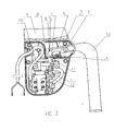
- FIGs 1-3 illustrate an embodiment of the safety switch device of the present invention in various operating positions and with the cover 40 (see Figure 4) removed for convenience.
- the safety switch device comprises a housing 9 upon which is mounted (on an internal pivot 2) an externally extending handle 13 and in which is accommodated a pressure activatable electric switch 10.
- a pressing member 8 is fixed on a slidable rod 12 which is inserted in a guiding groove in the interior of the housing 9. There are clearances 1 and 11 between the slideable rod 12 and the walls of the guiding groove.
- An engagement surface 5 on an internal portion 6 of the handle 13 presses against a curved surface 4 on an end portion of the slidable rod 12 so as to permit the slidable rod 12 to swing or move linearly (depending on the position of a safety press-button 3 - see below).
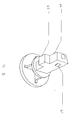
- the safety press-button 3 is slidably provided on the housing 9 and is shown in isolation in Figures 4 and 5.
- the safety press-button 3 comprises a main body 42 from which depends an arm 43.
- the safety press-button 3 has two working positions which advantageously leave the movement of the handle 13 unfettered. In the first working position, the safety press-button 3 is depressed and the arm 43 engages the lateral edge of the slideable rod 12. In the second working position, the safety press-button 3 is not depressed and the arm 43 is spaced apart from the lateral edge of the slideable rod 12.
- a retaining hook 41 retains the safety press button 3 in the housing 9. With the assistance of the guiding member 14, the safety press-button switches between the first and second press button.
- the safety switch device itself has essentially three operating positions.
- a spring 7 retains the slideable rod 12 in the guiding groove and generally biases the safety switch device to the third operating position illustrated in Figure 3.
Landscapes
- Mechanisms For Operating Contacts (AREA)
- Breakers (AREA)
- Switch Cases, Indication, And Locking (AREA)
Abstract
Description
Claims (8)
- A safety switch device comprising:a housing [9];a slidable rod [12] slidably positioned in a guiding groove in the interior of the housing [9], wherein a clearance [1,11] in the guiding groove is sufficient to permit the slidable rod [12] to move non-linearly;an externally extending handle [13] pivotally mounted on an internal pivot [2] in the housing [9], wherein an internal part [6] of the handle [13] presses against an end portion of the slidable rod [12] such that rotation of the handle [13] on the internal pivot [2] causes the slidable rod [12] to move;an electric switch [10] accommodated within the housing [9];a pressing member [8] mounted on the slidable rod [12] for activating the electric switch [10]; anda safety press-button [3] slidably provided on the housing [9], wherein in a first working position the safety press-button [3] presses against a lateral edge of the slidable rod [12] such that the slidable rod [12] is partially constrained to move linearly and in a second working position the safety press-button [3] is spaced apart from the lateral edge of the slidable rod [12] such that the slidable rod [12] is free to move non-linearly.
- A safety switch device as claimed in claim 1 wherein in a second working position the safety press-button [3] is spaced apart from the lateral edge of the slidable rod [12] such that the slidable rod [12] is free to swing.
- A safety switch device as claimed in claim 1 or 2, wherein when the handle [13] rotates a first engagement surface [5] on the end of the internal part of the handle [6] presses against a second engagement surface [4] of the end portion of the slideable rod [12].
- A safety switch device as claimed in any preceding claim wherein the pressing member is adapted to activate the electric switch [10] when the slidable rod [12] is partially constrained to move linearly.
- A safety switch device as claimed in any preceding claim wherein the pressing member is adapted not to activate the electric switch [10] when the slidable rod [12] is free to move non-linearly.
- A safety switch device comprising:wherein in a first working position at least one side of the safety press-button [3] orientedly presses against a lateral edge of the slidable rod [12] such that the slidable rod [12] is partially constrained to move linearly and in a second working position a sufficient room [1,11] around said slidable rod [12] is provided such that the slidable rod [12] is free to move non-linearly.a housing [9];a slidable rod [12] slidably lies in a guiding groove in the interior of the housing [9];an externally extending handle [13] pivotally mounted on an internal pivot [2] in the housing [9], wherein an internal part [6] of the handle [13] presses against an end portion of the slidable rod [12] such that rotation of the handle [13] on the internal pivot [2] causes the slidable rod [12] to move;an electric switch [10] accommodated within the housing [9];a pressing member [8] mounted on the slidable rod [12] for activating the electric switch [10]; anda safety press-button [3] slidably provided on the housing [9];
- A safety switch device as claimed in claim 6, wherein when the handle [13] rotates a first engagement surface [5] on the end of the internal part of the handle [6] slidably presses against a second engagement surface [4] of the end portion of the slidable rod [12].
- A safety switch device as claimed in claim 6 or 7, wherein said first engagement surface [5] on the end of the internal part of the handle [6] is a curved surface.
Applications Claiming Priority (2)
| Application Number | Priority Date | Filing Date | Title |
|---|---|---|---|
| CN02287611 | 2002-12-16 | ||
| CN02287611U CN2593341Y (en) | 2002-12-16 | 2002-12-16 | Safety switch |
Publications (2)
| Publication Number | Publication Date |
|---|---|
| EP1431998A2 true EP1431998A2 (en) | 2004-06-23 |
| EP1431998A3 EP1431998A3 (en) | 2006-02-01 |
Family
ID=29746757
Family Applications (1)
| Application Number | Title | Priority Date | Filing Date |
|---|---|---|---|
| EP03257590A Withdrawn EP1431998A3 (en) | 2002-12-16 | 2003-12-02 | Safety switch device |
Country Status (2)
| Country | Link |
|---|---|
| EP (1) | EP1431998A3 (en) |
| CN (1) | CN2593341Y (en) |
Cited By (5)
| Publication number | Priority date | Publication date | Assignee | Title |
|---|---|---|---|---|
| US11638397B2 (en) | 2020-02-10 | 2023-05-02 | Techtronic Cordless Gp | Control assembly coupled to handle of an implement |
| US12108702B2 (en) | 2012-10-15 | 2024-10-08 | Chervon (Hk) Limited | Gardening tool, particularly a mower |
| US12279552B2 (en) | 2021-12-08 | 2025-04-22 | Honda Motor Co., Ltd. | Blade control assembly, lawnmower, and method for operating a blade control assembly |
| US12364192B2 (en) | 2012-10-15 | 2025-07-22 | Chervon (Hk) Limited | Lawncare apparatus |
| US12520754B2 (en) | 2012-10-15 | 2026-01-13 | Chervon (Hk) Limited | Handle and control assembly for a mower |
Families Citing this family (1)
| Publication number | Priority date | Publication date | Assignee | Title |
|---|---|---|---|---|
| CN111029200B (en) * | 2020-01-07 | 2020-11-06 | 国网上海市电力公司 | A current overload protection knife for easy replacement of fuses |
Family Cites Families (6)
| Publication number | Priority date | Publication date | Assignee | Title |
|---|---|---|---|---|
| DE3006405A1 (en) * | 1980-02-21 | 1981-08-27 | Gardena Kress + Kastner Gmbh, 7900 Ulm | Hand held power tool with two operating pushbuttons - which cooperate and move shared rod that actuates shared switch, when both buttons are depressed |
| DE8414594U1 (en) * | 1984-05-12 | 1985-10-10 | Schulte-Elektrotechnik GmbH & Co KG, 5880 Lüdenscheid | Switch arrangement with switch-on lock |
| DE8511477U1 (en) * | 1985-04-18 | 1986-03-06 | TRIPUS-Kunststoffteile GmbH, 8870 Günzburg | Device for switching electrical devices on and off |
| DE3926098C2 (en) * | 1989-08-08 | 1995-08-10 | Brill Produktions Gmbh | Switch-on device for electrically operated devices |
| JP3329654B2 (en) * | 1996-03-22 | 2002-09-30 | 株式会社マキタ | Operation switch of electric lawn mower |
| GB2316458A (en) * | 1996-08-23 | 1998-02-25 | Electrolux Outdoor Prod Ltd | A switch actuating mechanism having lost motion means |
-
2002
- 2002-12-16 CN CN02287611U patent/CN2593341Y/en not_active Expired - Fee Related
-
2003
- 2003-12-02 EP EP03257590A patent/EP1431998A3/en not_active Withdrawn
Cited By (7)
| Publication number | Priority date | Publication date | Assignee | Title |
|---|---|---|---|---|
| US12108702B2 (en) | 2012-10-15 | 2024-10-08 | Chervon (Hk) Limited | Gardening tool, particularly a mower |
| US12364192B2 (en) | 2012-10-15 | 2025-07-22 | Chervon (Hk) Limited | Lawncare apparatus |
| US12520754B2 (en) | 2012-10-15 | 2026-01-13 | Chervon (Hk) Limited | Handle and control assembly for a mower |
| US12520755B2 (en) | 2012-10-15 | 2026-01-13 | Chervon (Hk) Limited | Mower with a controller device |
| US12532807B2 (en) | 2012-10-15 | 2026-01-27 | Chervon (Hk) Limited | Handle and safety control device for a mower |
| US11638397B2 (en) | 2020-02-10 | 2023-05-02 | Techtronic Cordless Gp | Control assembly coupled to handle of an implement |
| US12279552B2 (en) | 2021-12-08 | 2025-04-22 | Honda Motor Co., Ltd. | Blade control assembly, lawnmower, and method for operating a blade control assembly |
Also Published As
| Publication number | Publication date |
|---|---|
| CN2593341Y (en) | 2003-12-17 |
| EP1431998A3 (en) | 2006-02-01 |
Similar Documents
| Publication | Publication Date | Title |
|---|---|---|
| US4280026A (en) | Actuator mechanism for a portable, hand-held tool | |
| EP0028029B1 (en) | Portable electric tool | |
| US4757612A (en) | Fixed-blade knife with retractable blade cover | |
| US7254982B2 (en) | Electrohydraulic pressing device and method for operating the same | |
| WO2007088373A1 (en) | Power tool with removable handle portion | |
| ITMI971363A1 (en) | ELECTRIC HAMMER COMBINED | |
| EP1411534A1 (en) | Ambidextrous switch lockout system | |
| EP0333179A2 (en) | Improved trigger switch | |
| US8288670B2 (en) | Electric deadman switch for blast system | |
| JP4345371B2 (en) | Driving machine having an anti-missing device | |
| GB2380761A (en) | Electrical appliance with a removable power source | |
| CN102047815A (en) | Pruning shear | |
| EP1431998A3 (en) | Safety switch device | |
| US20020026717A1 (en) | Electrical power tool with a rotatable working tool | |
| JPH0142263Y2 (en) | ||
| EP0392428A2 (en) | Trigger switch | |
| EP0736886A3 (en) | Electric safety control assembly, particularly for gardening tools | |
| JP6932884B2 (en) | Enable switch | |
| JP3080822U (en) | Two-stage self-locking hand-held tool switch structure | |
| CN217086502U (en) | Control accessory and switch device | |
| JPH11114847A (en) | Screw fastening device | |
| AU2020102604A4 (en) | Switch for power tool | |
| JP2524664Y2 (en) | Trigger switch | |
| US20250132106A1 (en) | Trigger switch | |
| NL8001275A (en) | SWITCHING DEVICE. |
Legal Events
| Date | Code | Title | Description |
|---|---|---|---|
| PUAI | Public reference made under article 153(3) epc to a published international application that has entered the european phase |
Free format text: ORIGINAL CODE: 0009012 |
|
| AK | Designated contracting states |
Kind code of ref document: A2 Designated state(s): AT BE BG CH CY CZ DE DK EE ES FI FR GB GR HU IE IT LI LU MC NL PT RO SE SI SK TR |
|
| AX | Request for extension of the european patent |
Extension state: AL LT LV MK |
|
| PUAL | Search report despatched |
Free format text: ORIGINAL CODE: 0009013 |
|
| AK | Designated contracting states |
Kind code of ref document: A3 Designated state(s): AT BE BG CH CY CZ DE DK EE ES FI FR GB GR HU IE IT LI LU MC NL PT RO SE SI SK TR |
|
| AX | Request for extension of the european patent |
Extension state: AL LT LV MK |
|
| AKX | Designation fees paid | ||
| REG | Reference to a national code |
Ref country code: DE Ref legal event code: 8566 |
|
| STAA | Information on the status of an ep patent application or granted ep patent |
Free format text: STATUS: THE APPLICATION IS DEEMED TO BE WITHDRAWN |
|
| 18D | Application deemed to be withdrawn |
Effective date: 20060701 |