EP1431951A2 - Method and system for generating enhanced gray levels in an electromechanical grating display - Google Patents
Method and system for generating enhanced gray levels in an electromechanical grating display Download PDFInfo
- Publication number
- EP1431951A2 EP1431951A2 EP03078851A EP03078851A EP1431951A2 EP 1431951 A2 EP1431951 A2 EP 1431951A2 EP 03078851 A EP03078851 A EP 03078851A EP 03078851 A EP03078851 A EP 03078851A EP 1431951 A2 EP1431951 A2 EP 1431951A2
- Authority
- EP
- European Patent Office
- Prior art keywords
- pulse width
- width modulated
- modulated waveform
- ribbon elements
- electromechanical grating
- Prior art date
- Legal status (The legal status is an assumption and is not a legal conclusion. Google has not performed a legal analysis and makes no representation as to the accuracy of the status listed.)
- Withdrawn
Links
Images





Classifications
-
- G—PHYSICS
- G09—EDUCATION; CRYPTOGRAPHY; DISPLAY; ADVERTISING; SEALS
- G09G—ARRANGEMENTS OR CIRCUITS FOR CONTROL OF INDICATING DEVICES USING STATIC MEANS TO PRESENT VARIABLE INFORMATION
- G09G3/00—Control arrangements or circuits, of interest only in connection with visual indicators other than cathode-ray tubes
- G09G3/20—Control arrangements or circuits, of interest only in connection with visual indicators other than cathode-ray tubes for presentation of an assembly of a number of characters, e.g. a page, by composing the assembly by combination of individual elements arranged in a matrix no fixed position being assigned to or needed to be assigned to the individual characters or partial characters
- G09G3/2007—Display of intermediate tones
- G09G3/2077—Display of intermediate tones by a combination of two or more gradation control methods
-
- G—PHYSICS
- G02—OPTICS
- G02B—OPTICAL ELEMENTS, SYSTEMS OR APPARATUS
- G02B26/00—Optical devices or arrangements for the control of light using movable or deformable optical elements
- G02B26/08—Optical devices or arrangements for the control of light using movable or deformable optical elements for controlling the direction of light
- G02B26/0808—Optical devices or arrangements for the control of light using movable or deformable optical elements for controlling the direction of light by means of one or more diffracting elements
-
- G—PHYSICS
- G09—EDUCATION; CRYPTOGRAPHY; DISPLAY; ADVERTISING; SEALS
- G09G—ARRANGEMENTS OR CIRCUITS FOR CONTROL OF INDICATING DEVICES USING STATIC MEANS TO PRESENT VARIABLE INFORMATION
- G09G3/00—Control arrangements or circuits, of interest only in connection with visual indicators other than cathode-ray tubes
- G09G3/20—Control arrangements or circuits, of interest only in connection with visual indicators other than cathode-ray tubes for presentation of an assembly of a number of characters, e.g. a page, by composing the assembly by combination of individual elements arranged in a matrix no fixed position being assigned to or needed to be assigned to the individual characters or partial characters
- G09G3/34—Control arrangements or circuits, of interest only in connection with visual indicators other than cathode-ray tubes for presentation of an assembly of a number of characters, e.g. a page, by composing the assembly by combination of individual elements arranged in a matrix no fixed position being assigned to or needed to be assigned to the individual characters or partial characters by control of light from an independent source
- G09G3/3433—Control arrangements or circuits, of interest only in connection with visual indicators other than cathode-ray tubes for presentation of an assembly of a number of characters, e.g. a page, by composing the assembly by combination of individual elements arranged in a matrix no fixed position being assigned to or needed to be assigned to the individual characters or partial characters by control of light from an independent source using light modulating elements actuated by an electric field and being other than liquid crystal devices and electrochromic devices
-
- G—PHYSICS
- G09—EDUCATION; CRYPTOGRAPHY; DISPLAY; ADVERTISING; SEALS
- G09G—ARRANGEMENTS OR CIRCUITS FOR CONTROL OF INDICATING DEVICES USING STATIC MEANS TO PRESENT VARIABLE INFORMATION
- G09G2320/00—Control of display operating conditions
- G09G2320/06—Adjustment of display parameters
- G09G2320/0673—Adjustment of display parameters for control of gamma adjustment, e.g. selecting another gamma curve
Definitions
- This invention relates to an image-forming system containing an array of electromechanical grating devices. More particularly, the invention relates to the formation of gray levels in a projection display system containing a linear array of electromechanical grating devices.
- the light source is typically a white light lamp and the spatial light modulator is typically an area array containing liquid crystal devices or micromirror devices.
- Alternative display system architectures with one or more laser sources and spatial light modulators that are linear arrays of electromechanical grating devices show much promise for the future.
- the individual devices of these different spatial light modulators should be capable of rapidly producing a large number of gray levels in the image. The limit on the number of possible gray levels is usually dictated either by the device dynamics or by the speed of electronic components within the display system.
- Prior inventions have disclosed schemes for increasing the number of gray levels in the image without increasing the speed of the modulating elements or of the associated electronics. These schemes vary the illumination that is incident on the spatial light modulator during a frame.
- additional gray levels can be obtained with a micromirror device by using a variable neutral density filter to generate bright and dark gray levels.
- the dark gray scale is obtained by attenuating the illumination for some time during the display of a frame.
- the bright gray scale has no attenuation.
- the invention is implemented by rotating a filter wheel with a multi-segment neutral density filter in synchronization with the data stream.
- An alternative approach employs a pulsating light source, such as a pulsed laser to reduce speed requirements on the electronic components, as described in U.S. Patent No. 5,668,611, issued to Ernstoff et al. on September 16, 1997, entitled "FULL COLOR SEQUENTIAL IMAGE PROJECTION SYSTEM INCORPORATING PULSE RATE MODULATED ILLUMINATION.”
- the illumination on the spatial light modulator is adjusted by varying the pulse rate or pulse count.
- the average brightness of the light source is determined by the number of pulses.
- a complementary method uses direct intensity modulation of the light source to obtain multiple levels of brightness, as disclosed in U.S. Patent No. 5,903,323, issued to Ernstoff et al.
- Each of the above described inventions trade light source efficiency for improved gray levels or reduced electronic component speed requirements.
- efficient use of the light source is needed for high-quality projection displays in order to maximize brightness and color saturation of the projected image.
- an electromechanical conformal grating device consisting of ribbon elements suspended above a substrate by a periodic sequence of intermediate supports was disclosed by Kowarz in U.S. Patent No. 6,307,663, issued to Kowarz on October 23, 2001, entitled “SPATIAL LIGHT MODULATOR WITH CONFORMAL GRATING DEVICE.”
- the electromechanical conformal grating device is operated by electrostatic actuation, which causes the ribbon elements to conform around the support substructure, thereby producing a grating.
- the device of '663 has more recently become known as the conformal GEMS device, with GEMS standing for grating electromechanical system.
- the conformal GEMS device possesses a number of attractive features. It provides high-speed digital light modulation with high contrast and good efficiency.
- the active region is relatively large and the grating period is oriented perpendicular to the array direction. This orientation of the grating period causes diffracted light beams to separate in close proximity to the linear array and to remain spatially separated throughout most of an optical system and enables a simpler optical system design with smaller optical elements.
- Display systems based on a linear array of conformal GEMS devices were described by Kowarz et al. in U.S. Patent 6,411,425, entitled “ELECTROMECHANICAL GRATING DISPLAY SYSTEM WITH SPATIALLY SEPARATED LIGHT BEAMS, " issued June 25,2002 and by Kowarz et al. in U.S. Patent 6,476,848, entitled “ELECTROMECHANICAL GRATING DISPLAY SYSTEM WITH SEGMENTED WAVEPLATE, " issued Nov. 5, 2002.
- Fig. 1 shows two side-by-side conformal GEMS devices 5a and 5b in an unactuated state.
- the conformal GEMS devices 5a and 5b are formed on top of a substrate 10 covered by a bottom conductive layer 12, which acts as an electrode to actuate the devices 5a, 5b.
- the bottom conductive layer 12 is covered by a dielectric protective layer 14 followed by a standoff layer 16 and a spacer layer 18.
- a ribbon layer 20 is formed which is covered by a reflective layer and conductive layer 22.
- the reflective and conductive layer 22 provides electrodes for the actuation of the conformal GEMS devices 5a and 5b. Accordingly, the reflective and conductive layer 22 is patterned to provide electrodes for the two conformal GEMS devices 5a and 5b.
- the ribbon layer 20, preferably, comprises a material with a sufficient tensile stress to provide a large restoring force.
- Each of the two conformal GEMS devices 5a and 5b has an associated elongated ribbon element 23a and 23b, respectively, patterned from the reflective and conductive layer 22 and the ribbon layer 20.
- the elongated ribbon elements 23a and 23b are supported by end supports 24a and 24b, formed from the spacer layer 18, and by one or more intermediate supports 27 that are uniformly separated in order to form equal-width channels 25.
- the elongated ribbon elements 23a and 23b are secured to the end supports 24a and 24b and to the intermediate supports 27.
- a plurality of square standoffs 29 is patterned at the bottom of the channels 25 from the standoff layer 16. These standoffs 29 reduce the possibility of the elongated ribbon elements 23a and 23b sticking when actuated.
- FIG. 2 A top view of a four-device linear array of conformal GEMS devices 5a, 5b, 5c and 5d is shown in Fig. 2.
- the elongated ribbon elements 23a, 23b, 23c, and 23d are depicted partially removed over the portion of the diagram below the line A-A in order to show the underlying structure in an active region 8.
- the intermediate supports 27 should preferably be completely hidden below the elongated ribbon elements 23a, 23b, 23c, and 23d. Therefore, when viewed from the top, the intermediate supports 27 should not be visible in the gaps 28 between the conformal GEMS devices 5a-5d.
- each of the conformal GEMS devices 5a-5d has three intermediate supports 27 with four equal-width channels 25.
- the center-to-center separation A of the intermediate supports 27 defines the period of the conformal GEMS devices in the actuated state.
- the elongated ribbon elements 23a-23d are mechanically and electrically isolated from one another, allowing independent operation of the four conformal GEMS devices 5a-5d.
- the bottom conductive layer 12 of Fig. 1 can be common to all of the conformal GEMS devices 5a-5d.
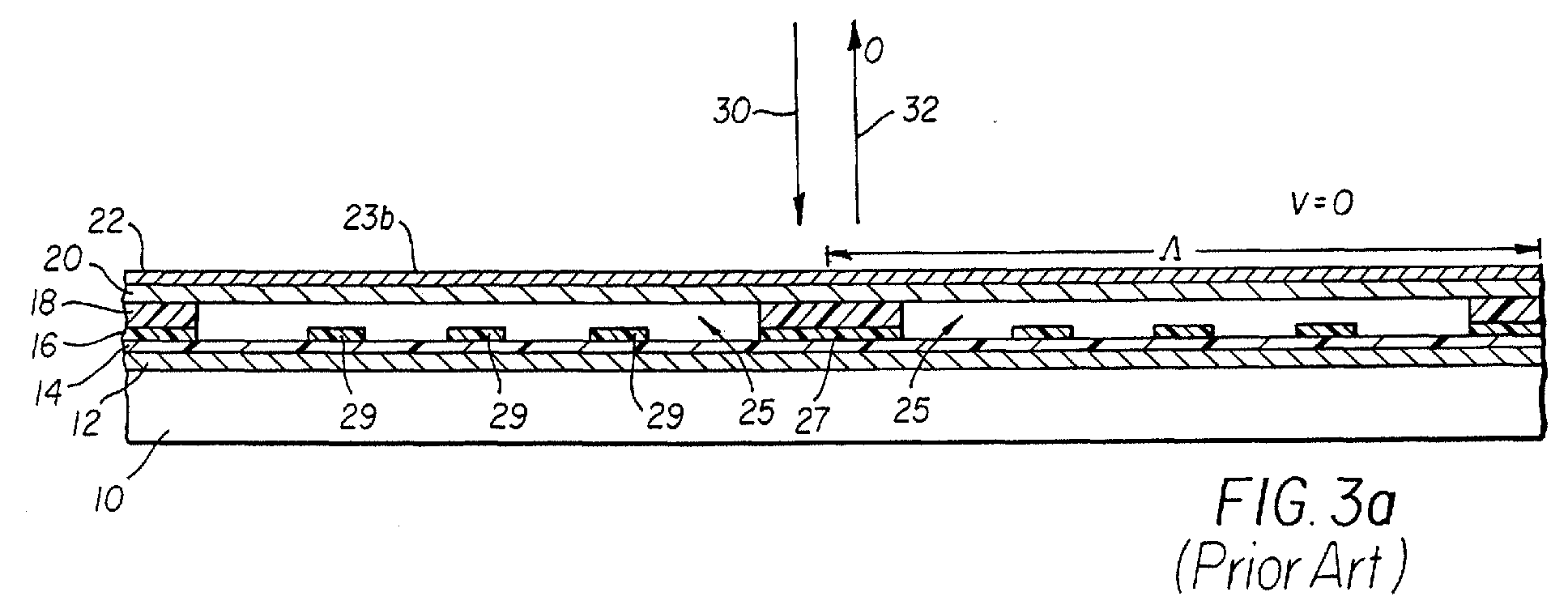
- Fig. 3a is a side view, through line 3,7-3,7 of Fig. 2, of two channels 25 of the conformal GEMS device 5b (as shown and described in Figs. 1 and 2) in an unactuated state.
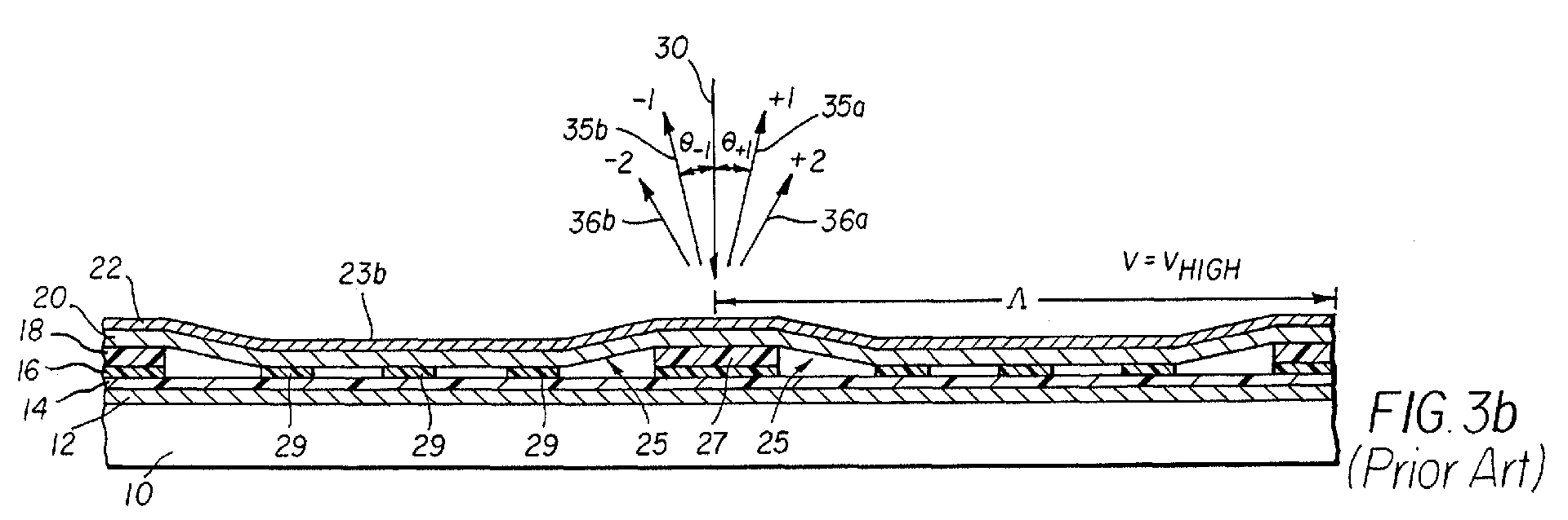
- Fig. 3b shows the same view for an actuated state.
- an attractive electrostatic force is produced by applying a voltage difference between the bottom conductive layer 12 and the reflective and conductive layer 22 of the elongated ribbon element 23b.
- V 0
- the ribbon element 23b is suspended flat between the supports.
- an incident light beam 30 is primarily reflected into a 0th order light beam 32, as in a simple planar mirror.
- a voltage is applied to the conformal GEMS device 5b, which deforms the elongated ribbon element 23b and produces a partially conformal grating with period A.
- the height difference between the bottom of element 23b and the top of the standoffs 29 is chosen to be approximately 1 ⁇ 4 of the wavelength ⁇ of the incident light. The optimum height depends on the specific conformal shape of the actuated device.
- the incident light beam 30 is primarily diffracted into the +1st order light beam 35a and -1st order light beam 35b, with additional light diffracted into the +2nd order 36a and -2nd order 36b.
- a small amount of light is diffracted into even higher orders and some light remains in the 0th order.
- one or more of the various beams can be collected and used by an optical system, depending on the application.
- Fig. 4 illustrates a display system containing a linear array 85 of conformal GEMS devices, as disclosed in U.S. Patent No. 6,411,425.
- a source 70 preferably a laser
- the display system forms an entire two-dimensional scene from a scan of a one-dimensional line image of the linear array 85 across the screen 90.
- the conformal GEMS devices of the linear array 85 are capable of rapidly modulating incident light to produce multiple lines of pixels with gray levels.
- the controller 80 selectively activates the linear array 85 to obtain the desired pixel pattern for a given line of a two-dimensional scene.
- a particular conformal GEMS device If a particular conformal GEMS device is not actuated, it reflects the incident light beam primarily into the 0th order light beam, which is directed back towards the source 70 by the turning mirror 82. If a particular conformal GEMS device is actuated, it diffracts the incident light beams primarily into +2 nd , +1 st , -1 st and -2 nd order light beams. These diffracted light beams pass around the turning mirror 82 and are projected on the screen 90 by the projection lens system 75. The scanning mirror 77 sweeps the line image across the screen 90 to form the two-dimensional image. Synchronization between the sweep of the scanning mirror 77 and the image data stream is provided by the controller 80.
- pulse-width-modulated (PWM) waveforms are applied to the conformal GEMS devices of the linear array 85, as described by Kowarz et al., "Conformal Grating Electromechanical System (GEMS) for High-Speed Digital Light Modulation," IEEE 15 th International MEMS Conference Technical Digest, pgs. 568-573 (2002).
- Fig. 5 shows a conventional single-level PWM waveform 45 with voltage V HIGH , together with the corresponding device's output (e.g., diffracted light intensity).
- the controller 80 selects the voltage pulse width in each modulation window 54, according to a data stream.
- the device When the single-level PWM waveform 45 transitions from 0 V to V HIGH , the device (for example, 5a and 5b shown in Fig.1 ) actuates and begins diffracting light. When the waveform transitions back to 0 V, the device stops diffracting light. This process is applied to each conformal GEMS device of the linear array 85.
- the modulation window 54 corresponds to the time used to form a single line of the two-dimensional image.
- the gray level perceived in a pixel of the image is, therefore, the integrated light intensity 52 within the modulation window 54.
- the applied voltage can be periodically switched between V HIGH and -V HIGH (see U. S. Patent 6,144,481). Since the force on the ribbon elements 23a-23d is independent of polarity, the diffracted light intensity is polarity independent.
- Fig. 6 shows an example of a gray scale 55 generated using the conventional single-level PWM approach of Fig. 5.
- relative gray levels are shown as a function of pulse width ( ⁇ V HIGH ) for a modulation window 54 of 20 ⁇ sec.
- pulse width is between 0.3 ⁇ sec and 20 ⁇ sec
- the relationship between gray level and pulse width is approximately linear.
- a non-monotonic (and nonlinear) region 50 is present, however, for pulse widths between approximately 0.3 ⁇ sec and 0.1 ⁇ sec. This non-monotonic behavior occurs because of the resonant dynamics of the conformal GEMS device.
- the particular shape of the non-monotonic region 50 depends on a number of factors, including device geometry and driver slew rate.
- the aforementioned need is met according to the present invention by providing a method for actuating an electromechanical grating device that has ribbon elements.
- the method includes the steps of: providing a data stream; generating a pulse width modulated waveform including at least two different non-zero voltages from the data stream; and applying the pulse width modulated waveform to the ribbon elements such that the ribbon elements transition through at least three different states of actuation that correspond to the pulse width modulated waveform.
- Another aspect of the present invention provides a system for actuating an electromechanical grating device that has ribbon elements.
- the system includes: a data source that provides a data stream; means for generating a pulse width modulated waveform including at least two different non-zero voltages from the data stream; and means for applying the pulse width modulated waveform to the ribbon elements such that the ribbon elements transition through at least three different states of actuation corresponding to the pulse width modulated waveform.
- a third aspect of the present invention provides an electromechanical grating device that includes a substrate and a set of elongated ribbon elements suspended above the substrate. Additionally, the electromechanical grating device includes means for generating a pulse width modulated waveform that has at least two different non-zero voltages from a data stream and means for applying the pulse width modulated waveform to the elongated ribbon elements such that the ribbon elements transition through at least three different states of actuation that correspond to the pulse width modulated waveform.
- the present invention has the added benefit of allowing better generation of the dark levels corresponding to the non-monotonic region 50 of Fig. 6.
- an additional voltage level V LOW is used to improve the generation of dark levels.
- the invention may also be applied to other electromechanical grating devices such as the Grating Light Valve (GLV) made by Silicon Light Machines.
- GLV Grating Light Valve
- V LOW When V LOW is applied to a conformal GEMS device, a partially actuated state is generated, as illustrated in Fig. 7.
- the electrostatic force generated by V LOW produces a slight deformation in the elongated ribbon element 23b and generates a weak grating with period ⁇ .
- the elongated ribbon element 23b therefore stays suspended well above the underlying structure, i.e., above the standoffs 29.
- V LOW is selected to be a few volts less than the pull-down voltage V PD , where the ribbon element 23b snaps into contact with the standoffs 29.
- Figure 8 which is a plot of normalized intensity versus applied voltage for a digital input signal, illustrates the selection of V LOW and V HIGH for a particular conformal GEMS device.
- V HIGH ⁇ 22V
- V PD ⁇ 20V
- V LOW ⁇ 16V.
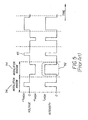
- Figure 9 illustrates a dual-level PWM waveform 51 for the present invention also showing the corresponding diffracted light intensity.
- the two voltage amplitudes V HIGH and V LOW generate associated intensity levels I HIGH and I LOW , respectively.
- the controller 80 selects the voltage amplitude (either V HIGH or V LOW ), the voltage pulse width, and (optionally) the polarity.
- the elongated ribbon elements of a conformal GEMS device actuate into contact with the standoffs, thereby causing diffraction of most of the incident light into the non-zero orders.
- the device At transitions from 0 V to ⁇ V LOW , the device partially actuates and diffracts a small percentage of light into the non-zero orders. As before, gray levels are obtained from the integrated light intensity 52 within a modulation window 54. Since the stress on the ribbon element is less in the partially actuated state than in the fully actuated state, and since the majority of image content is relatively dark, the use of a dual-level PWM waveform has the added benefit of reducing device aging.
- a gray scale 61 produced by the dual-level PWM waveform 51, of Fig. 9, is shown in Fig. 10.
- the two voltage amplitudes V HIGH and V LOW each have associated curves that relate gray level to pulse width.
- the controller 80 selects the voltage amplitude selected to be V HIGH , whereas for dark levels it is V LOW .
- a transition region, where the gray levels can be formed with either V HIGH or V LOW can be used to provide headroom for calibration between the two gray level curves so as to produce a smooth continuous gray scale.
- the clock rate of the dual-level PWM waveform 51 of the present invention is chosen to have HDTV resolution with 1,920 scanned lines (1,080 by 1,920 pixels), a frame rate of 60 Hz and a gray scale capability of 13 linear bits per color per frame (8,192 gray levels).
- the pulse width increment should be somewhat less than 1/(1,920*60*8,192) seconds ⁇ 1 nanoseconds to allow for some overhead for scanning.
- the digital electronics in the controller therefore, need to generate an effective PWM clock of approximately 1 GHz.
- This effective clock frequency can be reduced substantially by implementing dual-level PWM, while maintaining the same system specifications. For example, by choosing V HIGH and V LOW so that the ratio of the intensity levels is I LOW / I HIGH ⁇ 10, the effective PWM clock frequency can be reduced to approximately 100 MHz.
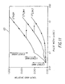
- a multi-level PWM waveform (not shown) with more than two voltage amplitudes can be used to further improve the gray scale 63 of an image, as illustrated in Fig. 11 for the case of tri-level pulse width modulation.
- the application of V HIGH causes the elongated ribbon elements to fully actuate into contact with the standoffs, whereas V LOW1 and V LOW2 ⁇ V LOW1 produce two different states of partial ribbon actuation.
- the gray scale 63 then consists of bright levels formed using V HIGH , dark levels (labeled dark levels 1 in Fig. 11) formed using V LOW1 and very dark levels (labeled dark levels 2 in Fig. 11) formed using V LOW2 . Transition regions can again be used at the intersections between the usable ranges of the different gray level curves.
- the arrows in Fig. 11, which point towards increasing gray levels, illustrate one example of a continuous gray scale 63 formed from three segments on the three curves.
- FIG. 12 shows a block diagram of an electronic architecture for implementing dual-level PWM in an image-forming system, which could be a projection display or a printing system.
- a data source 100 provides a (serial) data stream 105 that has been appropriately preprocessed for generating an image from a linear array of electromechanical grating devices, preferably an array of conformal GEMS devices. Since each electromechanical grating device 120 of the linear array has its own device driver 108, a serial-to-parallel converter 102 is needed to demultiplex the data stream 105 into the appropriate parallel data channels 115.
- each device driver 108 determines whether there would be 1080 parallel data channels 115 in order to address 1080 electromechanical grating devices 120, although only one of these parallel data channels 115 is shown in Fig. 12.
- the pulse-width-modulated output from each device driver 108 is determined by a pulse width generator 106 which controls the width of each voltage pulse via a clock 104, and a voltage selector 110 which selects the amplitude and polarity of each voltage pulse.
- the result is a dual-level PWM waveform similar to the waveform shown in Fig. 9.
- a method for generating enhanced image gray levels in an image-forming system with an electromechanical grating device comprising the steps of: a) providing a data stream; b) generating a pulse width modulated waveform including at least two different non-zero voltages from the data stream; and c) applying the pulse width modulated waveform to ribbon elements of the electromechanical grating device such that the ribbon elements transition through at least three different states of actuation corresponding to the pulse width modulated waveform such that gray levels for an image are produced.
- the method for generating enhanced image gray levels in an image-forming system with an electromechanical grating device wherein the at least three different states of actuation of the ribbon elements include an undeflected state, a partially deflected state, and a fully deflected state.
- the method for generating enhanced image gray levels in an image-forming system with an electromechanical grating device wherein the at least two different non-zero voltages include V HIGH , and V LOW .
- the method for generating enhanced image gray levels in an image-forming system with an electromechanical grating device wherein the ribbon elements make contact with an underlying structure when the pulse width modulated waveform is at V HIGH .
- the method for generating enhanced image gray levels in an image-forming system with an electromechanical grating device wherein the ribbon elements are suspended above an underlying structure when the pulse width modulated waveform is at V LOW .
- the method for generating enhanced image gray levels in an image-forming system with an electromechanical grating device wherein the at least two different non-zero voltages include V HIGH , V LOW , -V HIGH , and -V LOW .
- the method for generating enhanced image gray levels in an image-forming system with an electromechanical grating device wherein bright levels of the image are formed when the pulse width modulated waveform is at V HIGH , and wherein dark levels of the image are formed when the pulse width modulated waveform is at V LOW .
- the method for generating enhanced image gray levels in an image-forming system with an electromechanical grating device wherein a transition region with overlap exists between the bright levels of the image and the dark levels of the image.
- a method for generating enhanced gray levels in a display system including a linear array of electromechanical grating devices comprising the steps of: a) providing a data stream; b) generating a pulse width modulated waveform, including at least two different non-zero voltages from the data stream, for each electromechanical grating device in the linear array; and c) applying the pulse width modulated waveform to the electromechanical grating devices, wherein bright levels in an image are formed at one of the at least two different non-zero voltages and dark levels are formed at another of the at least two different non-zero voltages.
- the method for generating enhanced gray levels in a display system including a linear array of electromechanical grating devices further comprising the step of: d) forming bright levels and dark levels simultaneously by selecting one of the at least two different non-zero voltages for each electromechanical grating device of the linear array in accordance with the data stream.
- the method for generating enhanced gray levels in a display system including a linear array of electromechanical grating devices further comprising the step of: d) forming bright levels and dark levels sequentially by alternating the at least two different non-zero voltages between a V HIGH and a V LOW .
- the system for actuating an electromechanical grating device wherein the at least three different states of actuation of the ribbon elements include an undeflected state, a partially deflected state, and a fully deflected state.
- the system for actuating an electromechanical grating device wherein the at least two different non-zero voltages include V HIGH , and V LOW .
- the system for actuating an electromechanical grating device wherein the ribbon elements are suspended above an underlying structure when the pulse width modulated waveform is at V LOW .
- the system for actuating an electromechanical grating device wherein the at least two different non-zero voltages include V HIGH , V LOW , -V HIGH , and -V LOW .
- the image-forming system with enhanced gray levels wherein the plurality of diffracted light beams are selected from the group comprising: 0 th order, +1 st order, -1 st order, +2 nd order and -2 nd order.
- the image-forming system with enhanced gray levels wherein the at least two different non-zero voltages include V HIGH , and V LOW .
- the image-forming system with enhanced gray levels wherein the at least two different non-zero voltages include V HIGH , V LOW , -V HIGH , and -V LOW .
- the image-forming system with enhanced gray levels wherein the electromechanical grating device comprises suspended ribbon elements.
- the image-forming system with enhanced gray levels wherein the ribbon elements undergo at least three different states of actuation, including an undeflected state, a partially deflected state, and a fully deflected state.
- the image-forming system with enhanced gray levels wherein the suspended ribbon elements make contact with an underlying structure when the pulse width modulated waveform is at V HIGH .
- the image-forming system with enhanced gray levels wherein the suspended ribbon elements are spatially separated from an underlying structure when the pulse width modulated waveform is at V LOW .
- the image-forming system with enhanced gray levels is a projection display system.
- the image-forming system with enhanced gray levels is a printing system.
- the image-forming system with enhanced gray levels wherein the electromechanical grating device is illuminated by a laser.
- the method for generating enhanced image gray levels in an image-forming system with an electromechanical grating device wherein the electromechanical grating device is a conformal GEMS device.
- the method for generating enhanced gray levels in a display system including a linear array of electromechanical grating devices, wherein the electromechanical grating devices are conformal GEMS devices.
- An electromechanical grating device comprising: a) a substrate; b) a set of elongated ribbon elements suspended above the substrate; c) means for generating a pulse width modulated waveform, including at least two different non-zero voltages from a data stream; and c) means for applying the pulse width modulated waveform to the elongated ribbon elements such that the elongated ribbon elements transition through at least three different states of actuation that correspond to the pulse width modulated waveform.
- the electromechanical grating device wherein the at least three different states of actuation of the elongated ribbon elements include an undeflected state, a partially deflected state, and a fully deflected state.
- the electromechanical grating device wherein the at least two different non-zero voltages include V HIGH , and V LOW .
- the electromechanical grating device wherein the elongated ribbon elements make contact with an underlying structure when the pulse width modulated waveform is at V HIGH .
- the electromechanical grating device wherein the elongated ribbon elements are suspended above an underlying structure when the pulse width modulated waveform is at V LOW .
- the electromechanical grating device wherein the at least two different non-zero voltages include V HIGH , V LOW , -V HIGH , and -V LOW .
- the selection of voltage amplitude is done independently for every pixel image.
- the voltage amplitude applied to each electromechanical grating device of the linear array can be therefore selected independently.
- This approach provides the most flexible and is most light efficient. If there is sufficient illumination available from the light source, the voltage amplitude may be varied in a periodic fashion. For example, the waveform could transition from V HIGH to V LOW to -V HIGH to -V LOW on a line-by-line basis or frame-by-frame basis. Although simpler to implement, this approach wastes nearly half of the incident light.
Landscapes
- Physics & Mathematics (AREA)
- Engineering & Computer Science (AREA)
- General Physics & Mathematics (AREA)
- Computer Hardware Design (AREA)
- Theoretical Computer Science (AREA)
- Optics & Photonics (AREA)
- Mechanical Light Control Or Optical Switches (AREA)
- Control Of Indicators Other Than Cathode Ray Tubes (AREA)
Abstract
Description
Claims (11)
- A method for actuating an electromechanical grating device, including ribbon elements, comprising the steps of:a) providing a data stream;b) generating a pulse width modulated waveform including at least two different non-zero voltages from the data stream; andc) applying the pulse width modulated waveform to the ribbon elements such that the ribbon elements transition through at least three different states of actuation that correspond to the pulse width modulated waveform.
- The method claimed in claim 1, wherein the at least three different states of actuation of the ribbon elements include an undeflected state, a partially deflected state, and a fully deflected state.
- The method claimed in claim 1, wherein the at least two different non-zero voltages include VHIGH, and VLOW.
- The method claimed in claim 3, wherein the ribbon elements make contact with an underlying structure when the pulse width modulated waveform is at VHIGH.
- The method claimed in claim 3, wherein the ribbon elements are suspended above an underlying structure when the pulse width modulated waveform is at VLOW.
- The method claimed in claim 1, wherein the at least two different non-zero voltages include VHIGH, VLOW, -VHIGH, and -VLOW.
- A system for actuating an electromechanical grating device, containing ribbon elements comprising:a) a data source that provides a data stream;b) means for generating a pulse width modulated waveform including at least two different non-zero voltages from the data stream; andc) means for applying the pulse width modulated waveform to the ribbon elements such that the ribbon elements transition through at least three different states of actuation corresponding to the pulse width modulated waveform.
- An image-forming system with enhanced gray levels, comprising:a) a data source that provides a data stream;b) a serial-to-parallel converter for receiving the data stream and transmitting the data stream onto a pulse width generator, wherein the pulse width generator generates a pulse width modulated waveform;c) a clock for controlling the pulse width generator according to the data stream within a modulation window;d) an electromechanical grating device for diffracting an incident light beam into a plurality of diffracted light beams, and;e) a voltage selector for selecting between at least two different non-zero voltages for application to the electromechanical grating device, wherein bright levels in an image are formed at one of the at least two different non-zero voltages and dark levels are formed at another of the at least two different non-zero voltages.
- The method claimed in claim 1, wherein the electromechanical grating device is a conformal GEMS device.
- The system claimed in claim 7, wherein the electromechanical grating device is a conformal GEMS device.
- The image-forming system claimed in claim 8, wherein the electromechanical grating device is a conformal GEMS device.
Applications Claiming Priority (2)
| Application Number | Priority Date | Filing Date | Title |
|---|---|---|---|
| US320294 | 2002-12-16 | ||
| US10/320,294 US6717714B1 (en) | 2002-12-16 | 2002-12-16 | Method and system for generating enhanced gray levels in an electromechanical grating display |
Publications (2)
| Publication Number | Publication Date |
|---|---|
| EP1431951A2 true EP1431951A2 (en) | 2004-06-23 |
| EP1431951A3 EP1431951A3 (en) | 2009-12-30 |
Family
ID=32030479
Family Applications (1)
| Application Number | Title | Priority Date | Filing Date |
|---|---|---|---|
| EP03078851A Withdrawn EP1431951A3 (en) | 2002-12-16 | 2003-12-04 | Method and system for generating enhanced gray levels in an electromechanical grating display |
Country Status (4)
| Country | Link |
|---|---|
| US (1) | US6717714B1 (en) |
| EP (1) | EP1431951A3 (en) |
| JP (1) | JP4573522B2 (en) |
| CN (1) | CN1307458C (en) |
Families Citing this family (9)
| Publication number | Priority date | Publication date | Assignee | Title |
|---|---|---|---|---|
| US7826126B2 (en) * | 2003-11-01 | 2010-11-02 | Silicon Quest Kabushiki-Kaisha | Gamma correction for adjustable light source |
| US7148910B2 (en) * | 2003-11-06 | 2006-12-12 | Eastman Kodak Company | High-speed pulse width modulation system and method for linear array spatial light modulators |
| US7119936B2 (en) * | 2004-12-15 | 2006-10-10 | Eastman Kodak Company | Speckle reduction for display system with electromechanical grating |
| US7573631B1 (en) | 2005-02-22 | 2009-08-11 | Silicon Light Machines Corporation | Hybrid analog/digital spatial light modulator |
| WO2009032342A1 (en) * | 2007-09-06 | 2009-03-12 | Olympus Corporation | Gamma correction for adjustable light source |
| US20100066770A1 (en) * | 2008-09-18 | 2010-03-18 | Eastman Kodak Company | Pulse Width Modulation Display Pixels with Spatial Manipulation |
| US20100176855A1 (en) | 2009-01-12 | 2010-07-15 | Huffman James D | Pulse width modulated circuitry for integrated devices |
| US20100177129A1 (en) * | 2009-01-12 | 2010-07-15 | Fredlund John R | Artifact reduction in optical scanning displays |
| US20100177123A1 (en) * | 2009-01-12 | 2010-07-15 | Fredlund John R | Edge reproduction in optical scanning displays |
Family Cites Families (10)
| Publication number | Priority date | Publication date | Assignee | Title |
|---|---|---|---|---|
| US5495287A (en) * | 1992-02-26 | 1996-02-27 | Hitachi, Ltd. | Multiple-tone display system |
| US5668611A (en) | 1994-12-21 | 1997-09-16 | Hughes Electronics | Full color sequential image projection system incorporating pulse rate modulated illumination |
| US5841579A (en) * | 1995-06-07 | 1998-11-24 | Silicon Light Machines | Flat diffraction grating light valve |
| US5812303A (en) | 1996-08-15 | 1998-09-22 | Texas Instruments Incorporated | Light amplitude modulation with neutral density filters |
| US6038057A (en) * | 1998-12-18 | 2000-03-14 | Eastman Kodak Company | Method and system for actuating electro-mechanical ribbon elements in accordance to a data stream |
| US6144481A (en) * | 1998-12-18 | 2000-11-07 | Eastman Kodak Company | Method and system for actuating electro-mechanical ribbon elements in accordance to a data stream |
| US6233087B1 (en) * | 1998-12-18 | 2001-05-15 | Eastman Kodak Company | Electro-mechanical grating device |
| US6307663B1 (en) | 2000-01-26 | 2001-10-23 | Eastman Kodak Company | Spatial light modulator with conformal grating device |
| US6411425B1 (en) | 2000-09-27 | 2002-06-25 | Eastman Kodak Company | Electromechanical grating display system with spatially separated light beams |
| US6476848B2 (en) | 2000-12-21 | 2002-11-05 | Eastman Kodak Company | Electromechanical grating display system with segmented waveplate |
-
2002
- 2002-12-16 US US10/320,294 patent/US6717714B1/en not_active Expired - Fee Related
-
2003
- 2003-12-04 EP EP03078851A patent/EP1431951A3/en not_active Withdrawn
- 2003-12-16 JP JP2003417717A patent/JP4573522B2/en not_active Expired - Fee Related
- 2003-12-16 CN CNB200310120654XA patent/CN1307458C/en not_active Expired - Fee Related
Also Published As
| Publication number | Publication date |
|---|---|
| CN1508590A (en) | 2004-06-30 |
| EP1431951A3 (en) | 2009-12-30 |
| US6717714B1 (en) | 2004-04-06 |
| JP4573522B2 (en) | 2010-11-04 |
| JP2004199067A (en) | 2004-07-15 |
| HK1065598A1 (en) | 2005-02-25 |
| CN1307458C (en) | 2007-03-28 |
Similar Documents
| Publication | Publication Date | Title |
|---|---|---|
| EP1143287B1 (en) | Method and system for calibrating a diffractive grating modulator | |
| US6999224B2 (en) | Micromirror modulation method and digital apparatus with improved grayscale | |
| EP1553552B1 (en) | Method and system for generating color using a low-resolution modulator and a high-resolution modulator. | |
| US7224335B2 (en) | DMD-based image display systems | |
| US9368074B2 (en) | Optically addressed gray scale electric charge-accumulating spatial light modulator | |
| WO2009023275A1 (en) | Projection apparatus using variable light source | |
| HUT63723A (en) | Television projection arrangement, as well as method for displaying picture elements on screen | |
| US6724515B1 (en) | Conformal grating device for producing enhanced gray levels | |
| US20090147033A1 (en) | Color display system | |
| US7826126B2 (en) | Gamma correction for adjustable light source | |
| US7969640B2 (en) | Color display system | |
| US7787172B2 (en) | Gamma correction for adjustable light source | |
| US6717714B1 (en) | Method and system for generating enhanced gray levels in an electromechanical grating display | |
| US6525709B1 (en) | Miniature display apparatus and method | |
| US7595927B2 (en) | Spatial light modulator with sub-wavelength structure | |
| Brazas et al. | High-resolution laser-projection display system using a grating electromechanical system (GEMS) | |
| US8520290B2 (en) | Display system for higher grayscale with a varying light source | |
| US6795227B2 (en) | Method and apparatus for driving light-modulating elements | |
| US7075562B2 (en) | Optical scanning device | |
| US20050195137A1 (en) | Sequential color modulation method in display systems | |
| WO2009032346A1 (en) | Gamma correction for adjustable light source | |
| HK1065598B (en) | Method and system for generating enhanced gray levels in an electromechanical grating display | |
| HK1066278B (en) | Conformal grating device for producing enhanced gray levels | |
| KR100763397B1 (en) | Display device using MEMS | |
| US20080297903A1 (en) | Method for driving piezoelectric element or optical modulator including piezoelectric element |
Legal Events
| Date | Code | Title | Description |
|---|---|---|---|
| PUAI | Public reference made under article 153(3) epc to a published international application that has entered the european phase |
Free format text: ORIGINAL CODE: 0009012 |
|
| AK | Designated contracting states |
Kind code of ref document: A2 Designated state(s): AT BE BG CH CY CZ DE DK EE ES FI FR GB GR HU IE IT LI LU MC NL PT RO SE SI SK TR |
|
| AX | Request for extension of the european patent |
Extension state: AL LT LV MK |
|
| PUAL | Search report despatched |
Free format text: ORIGINAL CODE: 0009013 |
|
| AK | Designated contracting states |
Kind code of ref document: A3 Designated state(s): AT BE BG CH CY CZ DE DK EE ES FI FR GB GR HU IE IT LI LU MC NL PT RO SE SI SK TR |
|
| AX | Request for extension of the european patent |
Extension state: AL LT LV MK |
|
| 17P | Request for examination filed |
Effective date: 20100506 |
|
| 17Q | First examination report despatched |
Effective date: 20100610 |
|
| AKX | Designation fees paid |
Designated state(s): DE GB NL |
|
| STAA | Information on the status of an ep patent application or granted ep patent |
Free format text: STATUS: THE APPLICATION IS DEEMED TO BE WITHDRAWN |
|
| 18D | Application deemed to be withdrawn |
Effective date: 20101021 |