EP1431940A2 - Document path selector apparatus for use in a self-service terminal - Google Patents
Document path selector apparatus for use in a self-service terminal Download PDFInfo
- Publication number
- EP1431940A2 EP1431940A2 EP03256949A EP03256949A EP1431940A2 EP 1431940 A2 EP1431940 A2 EP 1431940A2 EP 03256949 A EP03256949 A EP 03256949A EP 03256949 A EP03256949 A EP 03256949A EP 1431940 A2 EP1431940 A2 EP 1431940A2
- Authority
- EP
- European Patent Office
- Prior art keywords
- cheque
- deflector
- document
- selector
- path
- Prior art date
- Legal status (The legal status is an assumption and is not a legal conclusion. Google has not performed a legal analysis and makes no representation as to the accuracy of the status listed.)
- Granted
Links
Images




Classifications
-
- G—PHYSICS
- G07—CHECKING-DEVICES
- G07F—COIN-FREED OR LIKE APPARATUS
- G07F19/00—Complete banking systems; Coded card-freed arrangements adapted for dispensing or receiving monies or the like and posting such transactions to existing accounts, e.g. automatic teller machines
- G07F19/20—Automatic teller machines [ATMs]
-
- B—PERFORMING OPERATIONS; TRANSPORTING
- B65—CONVEYING; PACKING; STORING; HANDLING THIN OR FILAMENTARY MATERIAL
- B65H—HANDLING THIN OR FILAMENTARY MATERIAL, e.g. SHEETS, WEBS, CABLES
- B65H29/00—Delivering or advancing articles from machines; Advancing articles to or into piles
- B65H29/58—Article switches or diverters
-
- G—PHYSICS
- G07—CHECKING-DEVICES
- G07D—HANDLING OF COINS OR VALUABLE PAPERS, e.g. TESTING, SORTING BY DENOMINATIONS, COUNTING, DISPENSING, CHANGING OR DEPOSITING
- G07D11/00—Devices accepting coins; Devices accepting, dispensing, sorting or counting valuable papers
- G07D11/10—Mechanical details
- G07D11/16—Handling of valuable papers
- G07D11/18—Diverting into different paths or containers
-
- G—PHYSICS
- G07—CHECKING-DEVICES
- G07D—HANDLING OF COINS OR VALUABLE PAPERS, e.g. TESTING, SORTING BY DENOMINATIONS, COUNTING, DISPENSING, CHANGING OR DEPOSITING
- G07D11/00—Devices accepting coins; Devices accepting, dispensing, sorting or counting valuable papers
- G07D11/40—Device architecture, e.g. modular construction
-
- G—PHYSICS
- G07—CHECKING-DEVICES
- G07F—COIN-FREED OR LIKE APPARATUS
- G07F19/00—Complete banking systems; Coded card-freed arrangements adapted for dispensing or receiving monies or the like and posting such transactions to existing accounts, e.g. automatic teller machines
- G07F19/20—Automatic teller machines [ATMs]
- G07F19/205—Housing aspects of ATMs
-
- B—PERFORMING OPERATIONS; TRANSPORTING
- B65—CONVEYING; PACKING; STORING; HANDLING THIN OR FILAMENTARY MATERIAL
- B65H—HANDLING THIN OR FILAMENTARY MATERIAL, e.g. SHEETS, WEBS, CABLES
- B65H2404/00—Parts for transporting or guiding the handled material
- B65H2404/60—Other elements in face contact with handled material
- B65H2404/61—Longitudinally-extending strips, tubes, plates, or wires
- B65H2404/611—Longitudinally-extending strips, tubes, plates, or wires arranged to form a channel
- B65H2404/6111—Longitudinally-extending strips, tubes, plates, or wires arranged to form a channel and shaped for curvilinear transport path
-
- B—PERFORMING OPERATIONS; TRANSPORTING
- B65—CONVEYING; PACKING; STORING; HANDLING THIN OR FILAMENTARY MATERIAL
- B65H—HANDLING THIN OR FILAMENTARY MATERIAL, e.g. SHEETS, WEBS, CABLES
- B65H2404/00—Parts for transporting or guiding the handled material
- B65H2404/60—Other elements in face contact with handled material
- B65H2404/63—Oscillating, pivoting around an axis parallel to face of material, e.g. diverting means
- B65H2404/632—Wedge member
Definitions
- the present invention relates to a self-service terminal, and is particularly directed to a document path selector apparatus for use in a self-service terminal, such as a cheque cashing ATM.
- a cheque cashing ATM allows a registered user, who typically does not have a bank account, to cash a cheque and receive money from the ATM in a public access, unattended environment.
- a user typically registers with an institution that owns or operates cheque cashing ATMs, and provides identification information (such as a social security number) and information about a cheque (usually a pay cheque) that he/she regularly receives.
- the registered user is typically provided with a card to initiate a cheque cashing transaction at a cheque cashing ATM.
- the cheque information typically includes details of how frequently a cheque is paid (for example, every week), who the cheque is paid by (that is, the payor of the cheque), the payor's bank details (for example, a bank code identifying the name of the bank), the typical amount that the cheque is made out for, and such like.
- a user enters his/her card at a cheque cashing ATM, then enters a cheque to be cashed through a cheque slot in the ATM's fascia.
- a cheque transport mechanism receives the entered cheque and transports the cheque in a forward direction along a cheque transport path to a number of locations within the ATM to process this cheque. If the cheque is valid, and the details printed on the cheque match the cheque information provided during registration, then the ATM informs the user of a surcharge that will be applied if the user wishes to cash the cheque. If the user does not agree to the surcharge, then the cheque is returned in the reverse direction along the cheque transport path to the user via the cheque slot.
- a self-service terminal comprises a fascia including means defining a document slot, and a document processing module including means defining a document processing zone, means defining a bi-directional document transport path which extends between the document slot and the document processing zone, and a document path selector mechanism disposed along the document transport path.
- the document path selector mechanism is provided for (i) enabling a document to be transported along the document transport path between the document slot and the document processing zone when parts of the document path selector mechanism are in a first position, and (ii) enabling a document to be transported along a divert path extending from the document processing zone to a location other than the document slot when parts of the document path selector mechanism are in a second position.
- the document path selector mechanism includes first and second movable deflector members and a movable selector member disposed between the first and second deflector members such that (i) the selector member and the first deflector member co-operate to define at least a portion of the document transport path extending between the document slot and the document processing zone when parts are in the first position, and (ii) the selector member and the second deflector member co-operate to define the divert path extending from the document processing zone to the location other than the document slot when parts are in the second position.
- the document path selector mechanism includes a linking member for linking the first and second deflector members such that the first and second deflector members move together as a unit when parts of the document path selector mechanism switch between the first and second positions.
- the first deflector member includes a stopping surface for engaging a deflector stop to limit the extent of movement of the first deflector member when parts are in the first position.
- the second deflector member includes a stopping surface for engaging a deflector stop to limit the extent of movement of the second deflector member when parts are in the second position.
- the selector member is separable apart from between the first and second deflector members to allow a document which is jammed between the selector member and one of the first and second deflector members to be removed.
- the document processing module may include a MICR reader disposed along the document transport path.
- an automated teller machine comprises an ATM fascia including (i) means defining a currency dispensing slot through which currency can be dispensed to an ATM customer, and (ii) means defining a cheque entrance/exit slot.
- the ATM also comprises a currency dispensing module for dispensing currency via the currency dispensing slot to an ATM customer.
- the ATM further comprises a cheque processing module for receiving a cheque from an ATM customer.
- the cheque processing module includes means defining a cheque processing zone, means defining a bi-directional cheque transport path which extends between the cheque entrance/exit slot and the cheque processing zone, and a cheque path selector mechanism disposed along the cheque transport path.
- the cheque path selector mechanism is provided for (i) enabling a cheque to be transported along the cheque transport path between the cheque entrance/exit slot and the cheque processing zone when parts of the cheque path selector mechanism are in a first position, and (ii) enabling a cheque to be transported along a divert path extending from the cheque processing zone to a location other than the cheque entrance/exit slot when parts of the cheque path selector mechanism are in a second position.
- the cheque path selector mechanism includes first and second movable deflector members and a movable selector member disposed between the first and second deflector members such that (i) the selector member and the first deflector member co-operate to define at least a portion of the cheque transport path extending between the cheque entrance/exit slot and the cheque processing zone when parts are in the first position, and (ii) the selector member and the second deflector member co-operate to define the divert path extending from the cheque processing zone to the location other than the cheque entrance/exit slot when parts are in the second position.
- the cheque path selector mechanism includes a linking member for linking the first and second deflector members such that the first and second deflector members move together as a unit when parts of the cheque path selector mechanism switch between the first and second positions.
- the first deflector member includes a stopping surface for engaging a deflector stop to limit the extent of movement of the first deflector member when parts are in the first position.
- the second deflector member includes a stopping surface for engaging a deflector stop to limit the extent of movement of the second deflector member when parts are in the second position.
- the selector member is separable apart from between the first and second deflector members to allow a cheque which is jammed between the selector member and one of the first and second deflector members to be removed.
- the cheque processing module may include a MICR reader disposed along the cheque transport path.
- a document path selector apparatus for use in a self-service terminal.
- the apparatus comprises first and second movable deflector members.
- the apparatus further comprises a movable selector member disposed between the first and second deflector members and movable between the first and second deflector members such that the selector member and the first deflector member co-operate to define at least a portion of a first document transport path of the self-service terminal when the selector member and the first deflector member are moved to a first position and the selector member and the second deflector member co-operate to define at least a portion of a second document transport path of the self-service terminal when the selector member and the second deflector member are in a second position which is different from the first position.
- a linking member links the first and second deflector members such that the first and second deflector members move together as a unit when the selector member switches between the first and second positions.
- the first deflector member includes a stopping surface for engaging a deflector stop to limit the extent of movement of the first deflector member when the selector member and the first deflector member are in the first position.
- the second deflector member includes a stopping surface for engaging a deflector stop to limit the extent of movement of the second deflector member when the selector member and the second deflector member are in the second position.
- the selector member is separable apart from between the first and second deflector members to allow a document which is jammed between the selector member and one of the first and second deflector members to be removed.
- Fig. 1 illustrates a self-service terminal 10 in the form of a cheque cashing ATM.
- the ATM 10 comprises a fascia 12 pivotably coupled to a chassis (not shown); an upper panel 14 mounted to the chassis and defining an aperture 16 through which a camera (not shown) images a user of the ATM 10; and a lower panel 18 hingeably coupled to the chassis (not shown) so that the lower panel 18 can be opened to reveal a safe (not shown) mounted in the chassis (not shown).
- the fascia 12 can be pivoted upwards to reveal ATM modules mounted within the chassis (not shown).
- the fascia 12 and lower panel 18 provide a user interface 20 for allowing a user to execute a transaction.
- the fascia 12 includes a handset 30 and a telephone keypad 32 for allowing a user to contact a remote operator (not shown) typically located in a call centre (not shown).
- the fascia 12 also includes an encrypting keyboard 34 for allowing a user to enter transaction details, and a display 36 for presenting screens to a user.
- the fascia 12 also defines eight slots for receiving and dispensing media items, and a tray 40 into which coins can be dispensed.
- the slots include: a money order printer slot 42, a bunch note input slot 44, a bunch note exit slot 46, a statement output slot 48, a cash dispense slot 50, a card reader slot 52, a card issue slot 54, and a cheque input/output slot 56.
- the slots 42 to 56 and tray 40 are arranged so that when the fascia 12 is closed, the slots and tray align with corresponding ATM modules mounted within the ATM's chassis (not shown).
- the user interface features described above are all provided on an NCR PERSONAS (trade mark) 5878 financial services centre ATM, available from NCR Financial Solutions Group Limited, Discovery Centre, 3 Fulton Road, Dundee, DD2 4SW, Scotland.
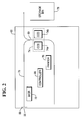
- Fig. 2 is a simplified schematic sectional diagram (along line 2-2 in Fig. 1) showing part of the fascia 12 and lower panel 18, and the main parts of the CPM 60.
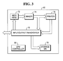
- Fig. 3 is a block diagram illustrating the main elements in the CPM 60.
- the CPM 60 is a modified version of a conventional cheque processing module, such as the cheque processing module provided with the PERSONAS (trade mark) 5878 NCR ATM.
- the CPM 60 comprises the following elements: a cheque input/output transport mechanism 70 including an alignment mechanism for aligning a cheque; a MICR head 72 for reading magnetic details on a code line of a cheque; an imager 74 including an upper 74a and lower 74b CCD camera for capturing an image of each side of a cheque (front and rear); a printer 76 for endorsing a cheque; and a storage bin 78 for storing processed cheques.
- the elements are conventional and will not be described in detail herein.
- the CPM 60 also includes a controller 86 for controlling the operation of the elements within the CPM 60.
- the CPM 60 also includes an entrance shutter 88 for opening and closing the cheque input/output slot 56.
- the CPM 60 further includes a divert gate 80 is in the form of a document path selector mechanism.
- the selector mechanism 80 includes a first deflector member 110 having a central portion 111 which is pivotable about a first pivot shaft 91.
- the first pivot shaft 91 is connected to a frame part (not shown) of the CPM 60.
- the first deflector 110 includes an end portion having a stopping surface 113 engageable with a first deflector stop 118 to limit extent of movement of the first deflector 110, and an opposite end portion having a tapered surface 116.
- the first deflector 110 also includes a curved major surface 114 and a tapered surface 115 which interconnects the stopping surface 113 and the curved major surface 114.
- the curved major surface 114 interconnects the tapered surface 115 and the tapered surface 116.
- the selector mechanism 80 includes a second deflector member 120 having a central portion 121 which is pivotable about a second pivot shaft 92.
- the second pivot shaft 92 is connected to the same frame part (not shown) to which the first pivot shaft 91 is connected.
- the second deflector 120 includes an end portion having a stopping surface 123 engageable with a second deflector stop 119 to limit extent of movement of the second deflector 120, and an opposite end portion having a tapered surface 126.
- the second deflector 120 also includes a curved major surface 124 and a tapered surface 125 which interconnects the stopping surface 123 and the curved major surface 124.
- the curved major surface 124 interconnects the tapered surface 125 and the tapered surface 126.
- a linking member 134 interconnects the first and second deflectors 110, 120.
- the selector mechanism 80 further includes a selector member 140 having a central portion 141 which is pivotable about a selector shaft 136.
- the selector shaft 136 is connected to another frame part (also not shown) of the CPM 60.
- the frame part to which the selector shaft 136 is connected is different from and separable away from the frame part to which the first and second pivot shafts 91, 92 of the first and second deflectors 110, 120 are connected.
- the selector 140 is movable away from the first and second deflectors 110, 120, as shown in Fig. 4. This allows a cheque that is jammed between the selector 140 and at least one of the first and second deflectors to be easily removed to clear the jam condition.
- the selector 140 includes first and second end portions 142, 144 and end portion 150 which lies opposite the first and second end portions 142, 144.
- the end portion 150 has a tapered surface 152 which faces the tapered surface 115 of the first deflector 110 and a tapered surface 154 which faces the tapered surface 125 of the second deflector 120.
- the first end portion 142 has a tapered surface 146 which faces the tapered surface 116 of the first deflector 110
- the second end portion 144 has a tapered surface 148 which faces the tapered surface 126 of the second deflector 120.
- a first curved major surface 156 interconnects the tapered surface 146 and the tapered surface 152.
- a second curved major surface 158 interconnects the tapered surface 148 and the tapered surface 154.
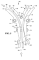
- the parts of the document path selector mechanism 80 are shown in Fig. 5 in a first position.
- a continuous document transport path 160 is formed between the major surface 114 of the first deflector 110 and the major surface 156 of the selector 140.
- the continuous path 160 forms a portion of the document transport path which extends between the cheque entrance/exit slot 56 and the zone in the vicinity of the endorser printer 76 (Fig. 1).
- the cheque When a cheque is transported from the slot 56 to the printer 76, the cheque moves along the document transport path including the path 160 in the direction of arrow A as shown in Fig. 5.
- the tapered surface 116 and the tapered surface 146 co-operate to minimize the chance of the cheque becoming jammed as the cheque initially enters into the path 160 in the direction of arrow A.
- the cheque moves along the document transport path including the path 160 in the direction of arrow B as shown in Fig. 5.
- the tapered surface 115 of the first deflector 110 and the tapered surface 152 of the selector 140 co-operate to minimize the chance of the cheque becoming jammed as the cheque initially enters into the path 160 in the direction of arrow B.
- the controller 86 commands an actuator (not shown) which pivots the selector 140 about the selector shaft 136 in a clockwise direction (as viewed looking at Fig. 5) to move the parts from the first position shown in Fig. 5 to the second position shown in Fig. 6.
- the selector 140 pivots clockwise about the selector shaft 136, the end portion of the curved major surface 156 in the vicinity of the tapered surface 152 moves against an end portion of the curved major surface 114 in the vicinity of the tapered surface 115 of the first deflector 110.
- the first deflector 110 pivots clockwise about the first deflector shaft 91. Since the first and second deflectors 110, 120 are interconnected by the linkage 134, the second deflector 120 rotates clockwise about the second deflector shaft 92 when the first deflector 110 rotates about the first shaft 91.
- a continuous divert path 162 is formed between the major surface 124 of the second deflector 120 and the major surface 158 of the selector 140.
- the divert path 162 extends from a portion the document transport path which extends from the zone in the vicinity of the endorser printer 76.
- the cheque enters the divert path 162 in the direction of arrow B as shown in Fig. 6.
- the tapered surface 125 of the second deflector 120 and the tapered surface 154 of the selector 140 co-operate to minimize the chance of the cheque becoming jammed as the cheque initially enters into divert path 162.
- the cheque eventually leaves the end of the divert path 162 (shown as arrow C in Fig.
- the tapered surface 126 of the second deflector 120 faces the tapered surface 148 of the selector 140 and goes into the storage bin 78.
- the storage bin 78 is shown located outside of the CPM 60, it is contemplated that the storage bin may be located inside the CPM.
- the controller 86 commands the actuator to rotate the selector 140 about the selector shaft 136 in a counter-clockwise direction (as viewed looking at Fig. 6) to move the parts from the position shown in Fig. 6 back to the position shown in Fig. 5.
- the selector 140 pivots counter-clockwise about the selector shaft 136, the end portion of the curved major surface 158 in the vicinity of the tapered surface 154 moves against an end portion of the curved major surface 124 in the vicinity of the tapered surface 125 of the second deflector 120.
- the second deflector 120 pivots counter-clockwise about the second deflector shaft 92. Since the first and second deflectors 110, 120 are interconnected by the linkage 134, the first deflector 110 rotates counter-clockwise about the first deflector shaft 91 when the second deflector 110 rotates about the second shaft 92. When parts of the selector mechanism 80 are returned back to the position as shown in Fig. 5, the continuous path 160 is again formed between the curved major surface 114 of the first deflector 110 and the curved major surface 156 of the selector 140.
- Fig. 7 is a flowchart 200 illustrating the steps involved in a cheque cashing transaction, and also with reference to Figs. 1 to 3.
- a user has registered with an institution owning and operating the ATM 10, and the user has informed the institution that he receives a weekly pay cheque for two hundred dollars, and has received a registration card for accessing cheque cashing functions at the ATM 10.
- the user enters the registration card into the card reader slot 52, selects "cheque cashing" from a list of transaction options presented on the display 36, and inserts the cheque to be cashed through the cheque input/output slot 56.
- the controller 86 opens the slot shutter 88 to receive the cheque, and the transport mechanism 70 transports the received cheque (step 210) to the MICR head 72 where a code line on the cheque is read (step 212).
- the transport mechanism 70 then transports the cheque to the imager 74, where both sides of the cheque are imaged (step 214).
- the controller 86 then verifies that the cheque has been completed correctly (step 216). If the cheque is incomplete, then the controller 86 initiates a cheque return operation, described below. If the cheque is complete, then the controller 86 verifies that the amount printed in a courtesy amount field on the cheque matches details provided by the user when the user registered with the institution operating the cheque cashing ATM 10 (step 218). In this example, the user registered a two hundred dollars cheque that was received weekly, and the cheque being presented is made out for two hundred dollars. If the amounts do not match, then the controller 86 initiates a cheque return operation, described hereinbelow. If the amounts do match, as in this example, then the display 36 displays the charge that will be deducted for cashing the cheque (step 220), in this example five dollars, and requests the user to confirm that he is willing to pay this charge to cash the cheque (step 222).
- the printer 76 prints endorsement data onto the cheque (step 224), and cash is dispensed through the cash dispense slot 50 to the user (step 226).
- the cash is to the value of the courtesy amount of the cheque minus the charge levied for cashing the cheque, in this example, one hundred and ninety five dollars.
- the cheque is then transported to the imager 74 to image the endorsed cheque (step 227) before it is transported to the storage bin 78 (step 228) for subsequent collection and further processing. If the user does not wish to pay the charge, then the controller 86 initiates a cheque return operation.
- the transport mechanism 70 reverses the direction of transport (step 240) to convey the cheque to the cheque input/output slot 56 to return the cheque to the user via the cheque input/output slot.
- the controller 86 may monitor the slot 56 to ensure that the cheque has been removed by the user (step 242). If the user has not removed the cheque within a predetermined time period, the cheque is retracted and conveyed to a reject bin (not shown) (step 244).
- the above-description describes a cheque being cashed in its entire amount by an ATM customer, it is contemplated that the cheque may be cashed only in partial amount of the entire amount of the cheque at the ATM 10, with the remaining amount of the cheque being deposited to a banking account. It is also conceivable that the entire amount of the cheque be deposited by an ATM customer into a banking account.
- a number of advantages result by providing the document path selector mechanism 80 in accordance with the present invention.
- One advantage is that the construction of the selector mechanism 80 is relatively compact and, therefore occupies relatively less space within the ATM.
- Another advantage is that the selector mechanism 80 is operable requiring minimal movement of its parts. This provides additional compactness.
- Still another advantage is that the selector 140 can be easily separated apart from the first and second deflectors 110, 120 to allow a jammed cheque to be quickly and easily removed when a jam condition occurs.
Landscapes
- Physics & Mathematics (AREA)
- General Physics & Mathematics (AREA)
- Business, Economics & Management (AREA)
- Accounting & Taxation (AREA)
- Finance (AREA)
- Engineering & Computer Science (AREA)
- Mechanical Engineering (AREA)
- Separation, Sorting, Adjustment, Or Bending Of Sheets To Be Conveyed (AREA)
- Coupling Device And Connection With Printed Circuit (AREA)
Abstract
Description
Claims (14)
- A self-service terminal comprising:a fascia including means defining a document slot; and a document processing module including means defining a document processing zone, means defining a bi-directional document transport path which extends between the document slot and the document processing zone, and a document path selector mechanism disposed along the document transport path for (i) enabling a document to be transported along the document transport path between the document slot and the document processing zone when parts of the document path selector mechanism are in a first position, and (ii) enabling a document to be transported along a divert path extending from the document processing zone to a location other than the document slot when parts of the document path selector mechanism are in a second position; the document path selector mechanism including first and second movable deflector members and a movable selector member disposed between the first and second deflector members such that (i) the selector member and the first deflector member co-operate to define at least a portion of the document transport path extending between the document slot and the document processing zone when parts are in the first position, and (ii) the selector member and the second deflector member co-operate to define the divert path extending from the document processing zone to the location other than the document slot when parts are in the second position.
- A terminal according to claim 1, wherein the document path selector mechanism includes a linking member for linking the first and second deflector members such that the first and second deflector members move together as a unit when parts of the document path selector mechanism switch between the first and second positions.
- A terminal according to claim 2, wherein (i) the first deflector member includes a stopping surface for engaging a deflector stop to limit the extent of movement of the first deflector member when parts are in the first position, and (ii) the second deflector member includes a stopping surface for engaging a deflector stop to limit the extent of movement of the second deflector member when parts are in the second position.
- A terminal according to claim 1, wherein the selector member is separable apart from between the first and second deflector members to allow a document which is jammed between the selector member and one of the first and second deflector members to be removed.
- A terminal according to claim 1, wherein the document processing module includes a MICR reader disposed along the document transport path.
- An automated teller machine (ATM) comprising:an ATM fascia including (i) means defining a currency dispensing slot through which currency can be dispensed to an ATM customer, and (ii) means defining a cheque entrance/exit slot;a currency dispensing module for dispensing currency via the currency dispensing slot to an ATM customer; anda cheque processing module for receiving a cheque from an ATM customer, the cheque processing module including means defining a cheque processing zone, means defining a bi-directional cheque transport path which extends between the cheque entrance/exit slot and the cheque processing zone, and a cheque path selector mechanism disposed along the cheque transport path for (i) enabling a cheque to be transported along the cheque transport path between the cheque entrance/exit slot and the cheque processing zone when parts of the cheque path selector mechanism are in a first position, and (ii) enabling a cheque to be transported along a divert path extending from the cheque processing zone to a location other than the cheque entrance/exit slot when parts of the cheque path selector mechanism are in a second position;the cheque path selector mechanism including first and second movable deflector members and a movable selector member disposed between the first and second deflector members such that (i) the selector member and the first deflector member co-operate to define at least a portion of the cheque transport path extending between the cheque entrance/exit slot and the cheque processing zone when parts are in the first position, and (ii) the selector member and the second deflector member co-operate to define the divert path extending from the cheque processing zone to the location other than the cheque entrance/exit slot when parts are in the second position.
- An ATM according to claim 6, wherein the cheque path selector mechanism includes a linking member for linking the first and second deflector members such that the first and second deflector members move together as a unit when parts of the cheque path selector mechanism switch between the first and second positions.
- An ATM according to claim 7, wherein (i) the first deflector member includes a stopping surface for engaging a deflector stop to limit the extent of movement of the first deflector member when parts are in the first position, and (ii) the second deflector member includes a stopping surface for engaging a deflector stop to limit the extent of movement of the second deflector member when parts are in the second position.
- An ATM according to claim 6, wherein the selector member is separable apart from between the first and second deflector members to allow a cheque which is jammed between the selector member and one of the first and second deflector members to be removed.
- An ATM according to claim 6, wherein the cheque processing module includes a MICR reader disposed along the cheque transport path.
- A document path selector apparatus for use in a self-service terminal, the apparatus comprising:first and second movable deflector members; anda movable selector member disposed between the first and second deflector members and movable between the first and second deflector members such that the selector member and the first deflector member co-operate to define at least a portion of a first document transport path of the self-service terminal when the selector member and the first deflector member are moved to a first position and the selector member and the second deflector member co-operate to define at least a portion of a second document transport path of the self-service terminal when the selector member and the second deflector member are in a second position which is different from the first position.
- An apparatus according to claim 11, further comprising a linking member for linking the first and second deflector members such that the first and second deflector members move together as a unit when the selector member switches between the first and second positions.
- An apparatus according to claim 12, wherein (i) the first deflector member includes a stopping surface for engaging a deflector stop to limit the extent of movement of the first deflector member when the selector member and the first deflector member are in the first position, and (ii) the second deflector member includes a stopping surface for engaging a deflector stop to limit the extent of movement of the second deflector member when the selector member and the second deflector member are in the second position.
- An apparatus according to claim 11, wherein the selector member is separable apart from between the first and second deflector members to allow a document which is jammed between the selector member and one of the first and second deflector members to be removed.
Applications Claiming Priority (2)
| Application Number | Priority Date | Filing Date | Title |
|---|---|---|---|
| US325345 | 2002-12-19 | ||
| US10/325,345 US6981636B2 (en) | 2002-12-19 | 2002-12-19 | Document path selector apparatus for use in a self-service terminal |
Publications (3)
| Publication Number | Publication Date |
|---|---|
| EP1431940A2 true EP1431940A2 (en) | 2004-06-23 |
| EP1431940A3 EP1431940A3 (en) | 2005-01-12 |
| EP1431940B1 EP1431940B1 (en) | 2008-04-23 |
Family
ID=32393098
Family Applications (1)
| Application Number | Title | Priority Date | Filing Date |
|---|---|---|---|
| EP03256949A Expired - Lifetime EP1431940B1 (en) | 2002-12-19 | 2003-11-04 | Document path selector apparatus for use in a self-service terminal |
Country Status (4)
| Country | Link |
|---|---|
| US (1) | US6981636B2 (en) |
| EP (1) | EP1431940B1 (en) |
| DE (1) | DE60320517T2 (en) |
| ES (1) | ES2301760T3 (en) |
Cited By (2)
| Publication number | Priority date | Publication date | Assignee | Title |
|---|---|---|---|---|
| WO2016197363A1 (en) * | 2015-06-11 | 2016-12-15 | 深圳怡化电脑股份有限公司 | Cash depositing and dispensing device and automatic teller machine |
| CN117275150A (en) * | 2022-06-21 | 2023-12-22 | Ncr公司 | Media item transfer |
Families Citing this family (9)
| Publication number | Priority date | Publication date | Assignee | Title |
|---|---|---|---|---|
| SG122813A1 (en) * | 2003-01-24 | 2006-06-29 | Seiko Epson Corp | Printing apparatus and printing method |
| JP4598591B2 (en) * | 2005-04-28 | 2010-12-15 | 京セラミタ株式会社 | Paper transport branch device |
| US8052041B2 (en) * | 2006-11-10 | 2011-11-08 | Diebold Self-Service Systems Division Of Diebold, Incorporated | Method of operation of card activated automated banking machine |
| US8061712B2 (en) * | 2007-01-26 | 2011-11-22 | Canon Kabushiki Kaisha | Sheet conveying apparatus and image forming apparatus |
| US8002118B2 (en) * | 2008-08-18 | 2011-08-23 | Burroughs Payment Systems, Inc. | Pocket selector gate with self locking geometry |
| JP2012206497A (en) | 2011-03-15 | 2012-10-25 | Seiko Epson Corp | Multifunction printing device |
| JP5479439B2 (en) * | 2011-11-30 | 2014-04-23 | 京セラドキュメントソリューションズ株式会社 | Sheet conveying apparatus and image forming apparatus having the same |
| TWI622961B (en) | 2017-06-27 | 2018-05-01 | 鴻發國際科技股份有限公司 | Convey path switching module, paper sheet handling module and paper sheet handling apparatus |
| CN110288756B (en) * | 2018-03-13 | 2021-12-21 | 山东新北洋信息技术股份有限公司 | Sheet-like medium conveying device and cash recycling device |
Family Cites Families (15)
| Publication number | Priority date | Publication date | Assignee | Title |
|---|---|---|---|---|
| GB973579A (en) | 1961-12-21 | 1964-10-28 | Ass Elect Ind | Improvements relating to sorting apparatus for card-like items |
| DE2757848A1 (en) | 1977-12-23 | 1979-06-28 | Agfa Gevaert Ag | DEVICE FOR SORTING PHOTOGRAPHIC IMAGES |
| JPS57203648A (en) | 1981-06-09 | 1982-12-14 | Canon Inc | Sheet branch device |
| US4494743A (en) * | 1981-08-31 | 1985-01-22 | Docutel Corporation | Dispenser picker apparatus |
| DE8803496U1 (en) | 1988-03-15 | 1988-05-11 | Nixdorf Computer Ag, 4790 Paderborn | Printer with a plurality of output channels for recording media |
| US5150894A (en) * | 1991-03-27 | 1992-09-29 | Bell & Howell Company | Diverter mechanism for flat document conveyor system |
| JP3292600B2 (en) | 1994-07-27 | 2002-06-17 | 株式会社リコー | Paper reversing device |
| JP3408916B2 (en) * | 1996-03-12 | 2003-05-19 | 株式会社日立製作所 | Paper sorter |
| US5788227A (en) * | 1996-05-21 | 1998-08-04 | Hewlett-Packard Company | Beltless cut sheet media feeder and method for feeding and ejecting sheets to and from a scanner apparatus |
| US6273413B1 (en) * | 1997-11-28 | 2001-08-14 | Diebold, Incorporated | Automated banking machine with sheet directing apparatus |
| GB9800431D0 (en) | 1997-11-05 | 1998-03-04 | Ncr Int Inc | Document routing mechanism |
| US6398212B1 (en) * | 1998-12-18 | 2002-06-04 | Canon Kabushiki Kaisha | Sheet surface reversing device and image forming apparatus having the same |
| CN1222900C (en) * | 1999-08-09 | 2005-10-12 | 第一数据公司 | Point of sale payment terminal |
| GB0007361D0 (en) * | 2000-03-28 | 2000-05-17 | Ncr Int Inc | Self-service terminal |
| DE10046468A1 (en) * | 2000-09-20 | 2002-03-28 | Heidelberger Druckmasch Ag | Device for distributing flexible sheet-like objects |
-
2002
- 2002-12-19 US US10/325,345 patent/US6981636B2/en not_active Expired - Lifetime
-
2003
- 2003-11-04 DE DE60320517T patent/DE60320517T2/en not_active Expired - Lifetime
- 2003-11-04 EP EP03256949A patent/EP1431940B1/en not_active Expired - Lifetime
- 2003-11-04 ES ES03256949T patent/ES2301760T3/en not_active Expired - Lifetime
Cited By (3)
| Publication number | Priority date | Publication date | Assignee | Title |
|---|---|---|---|---|
| WO2016197363A1 (en) * | 2015-06-11 | 2016-12-15 | 深圳怡化电脑股份有限公司 | Cash depositing and dispensing device and automatic teller machine |
| CN117275150A (en) * | 2022-06-21 | 2023-12-22 | Ncr公司 | Media item transfer |
| EP4296984A1 (en) * | 2022-06-21 | 2023-12-27 | NCR Corporation | Media item transport |
Also Published As
| Publication number | Publication date |
|---|---|
| DE60320517T2 (en) | 2009-04-16 |
| US20040118910A1 (en) | 2004-06-24 |
| EP1431940A3 (en) | 2005-01-12 |
| EP1431940B1 (en) | 2008-04-23 |
| US6981636B2 (en) | 2006-01-03 |
| DE60320517D1 (en) | 2008-06-05 |
| ES2301760T3 (en) | 2008-07-01 |
Similar Documents
| Publication | Publication Date | Title |
|---|---|---|
| US7639859B2 (en) | Method of operating a remote check image capture device and an apparatus therefor | |
| US7424969B2 (en) | Cheque deposit at a self-service terminal | |
| US7391934B2 (en) | Method of creating a substitute check using check image data from a remote check image capture device and an apparatus therefor | |
| US6981638B2 (en) | Automated banking machine | |
| US7798398B2 (en) | Check cashing automated banking machine | |
| US7461773B2 (en) | Method of operating an image-based self-service check depositing terminal in response to a fault condition | |
| EP1542182A2 (en) | Automated teller machine | |
| US20150076223A1 (en) | Check cashing banking system controlled responsive to data bearing records | |
| US6981636B2 (en) | Document path selector apparatus for use in a self-service terminal | |
| US6789795B2 (en) | Variable pressure document infeed transport apparatus for use in a self-service terminal | |
| EP1671909A1 (en) | Document stacker apparatus and method of stacking documents | |
| US7051927B2 (en) | Apparatus for use in a self-service terminal and a method of processing a financial instrument at a self-service terminal | |
| US6758395B2 (en) | Self-service terminal | |
| US7051928B2 (en) | Document diverter apparatus for use in a self-service terminal | |
| US7128260B1 (en) | Methods of an operator handling a fault condition in an image-based self-service check depositing terminal | |
| US8783558B2 (en) | Image-based check depositing automated teller machine (ATM) and method of operating an image-based check depositing ATM | |
| US7522759B2 (en) | Self-service terminal | |
| EP1507241A1 (en) | Method of consolidating remotely captured cheque image data and a consolidation server therefor | |
| EP1646020A1 (en) | Method of operating an image-based self-service terminal and an apparatus therefor |
Legal Events
| Date | Code | Title | Description |
|---|---|---|---|
| PUAI | Public reference made under article 153(3) epc to a published international application that has entered the european phase |
Free format text: ORIGINAL CODE: 0009012 |
|
| AK | Designated contracting states |
Kind code of ref document: A2 Designated state(s): AT BE BG CH CY CZ DE DK EE ES FI FR GB GR HU IE IT LI LU MC NL PT RO SE SI SK TR |
|
| AX | Request for extension of the european patent |
Extension state: AL LT LV MK |
|
| PUAL | Search report despatched |
Free format text: ORIGINAL CODE: 0009013 |
|
| AK | Designated contracting states |
Kind code of ref document: A3 Designated state(s): AT BE BG CH CY CZ DE DK EE ES FI FR GB GR HU IE IT LI LU MC NL PT RO SE SI SK TR |
|
| AX | Request for extension of the european patent |
Extension state: AL LT LV MK |
|
| 17P | Request for examination filed |
Effective date: 20050712 |
|
| AKX | Designation fees paid |
Designated state(s): DE ES FR GB IT |
|
| 17Q | First examination report despatched |
Effective date: 20051125 |
|
| GRAP | Despatch of communication of intention to grant a patent |
Free format text: ORIGINAL CODE: EPIDOSNIGR1 |
|
| GRAS | Grant fee paid |
Free format text: ORIGINAL CODE: EPIDOSNIGR3 |
|
| GRAA | (expected) grant |
Free format text: ORIGINAL CODE: 0009210 |
|
| AK | Designated contracting states |
Kind code of ref document: B1 Designated state(s): DE ES FR GB IT |
|
| REG | Reference to a national code |
Ref country code: GB Ref legal event code: FG4D |
|
| REF | Corresponds to: |
Ref document number: 60320517 Country of ref document: DE Date of ref document: 20080605 Kind code of ref document: P |
|
| REG | Reference to a national code |
Ref country code: DE Ref legal event code: R096 Ref document number: 60320517 Country of ref document: DE Effective date: 20080605 |
|
| REG | Reference to a national code |
Ref country code: ES Ref legal event code: FG2A Ref document number: 2301760 Country of ref document: ES Kind code of ref document: T3 |
|
| ET | Fr: translation filed | ||
| REG | Reference to a national code |
Ref country code: DE Ref legal event code: R084 Ref document number: 60320517 Country of ref document: DE Effective date: 20081006 |
|
| PLBE | No opposition filed within time limit |
Free format text: ORIGINAL CODE: 0009261 |
|
| STAA | Information on the status of an ep patent application or granted ep patent |
Free format text: STATUS: NO OPPOSITION FILED WITHIN TIME LIMIT |
|
| 26N | No opposition filed |
Effective date: 20090126 |
|
| REG | Reference to a national code |
Ref country code: DE Ref legal event code: R097 Ref document number: 60320517 Country of ref document: DE Effective date: 20090126 |
|
| REG | Reference to a national code |
Ref country code: GB Ref legal event code: 746 Effective date: 20091111 |
|
| PG25 | Lapsed in a contracting state [announced via postgrant information from national office to epo] |
Ref country code: IT Free format text: LAPSE BECAUSE OF NON-PAYMENT OF DUE FEES Effective date: 20091104 |
|
| PGRI | Patent reinstated in contracting state [announced from national office to epo] |
Ref country code: IT Effective date: 20110616 |
|
| REG | Reference to a national code |
Ref country code: FR Ref legal event code: PLFP Year of fee payment: 13 |
|
| REG | Reference to a national code |
Ref country code: FR Ref legal event code: PLFP Year of fee payment: 14 |
|
| REG | Reference to a national code |
Ref country code: FR Ref legal event code: PLFP Year of fee payment: 15 |
|
| PGFP | Annual fee paid to national office [announced via postgrant information from national office to epo] |
Ref country code: IT Payment date: 20221123 Year of fee payment: 20 Ref country code: GB Payment date: 20221128 Year of fee payment: 20 Ref country code: FR Payment date: 20221123 Year of fee payment: 20 Ref country code: ES Payment date: 20221201 Year of fee payment: 20 Ref country code: DE Payment date: 20221125 Year of fee payment: 20 |
|
| P01 | Opt-out of the competence of the unified patent court (upc) registered |
Effective date: 20230512 |
|
| REG | Reference to a national code |
Ref country code: DE Ref legal event code: R071 Ref document number: 60320517 Country of ref document: DE |
|
| REG | Reference to a national code |
Ref country code: ES Ref legal event code: FD2A Effective date: 20231124 |
|
| REG | Reference to a national code |
Ref country code: GB Ref legal event code: PE20 Expiry date: 20231103 |
|
| PG25 | Lapsed in a contracting state [announced via postgrant information from national office to epo] |
Ref country code: GB Free format text: LAPSE BECAUSE OF EXPIRATION OF PROTECTION Effective date: 20231103 |
|
| PG25 | Lapsed in a contracting state [announced via postgrant information from national office to epo] |
Ref country code: ES Free format text: LAPSE BECAUSE OF EXPIRATION OF PROTECTION Effective date: 20231105 |
|
| PG25 | Lapsed in a contracting state [announced via postgrant information from national office to epo] |
Ref country code: GB Free format text: LAPSE BECAUSE OF EXPIRATION OF PROTECTION Effective date: 20231103 Ref country code: ES Free format text: LAPSE BECAUSE OF EXPIRATION OF PROTECTION Effective date: 20231105 |