EP1431754A2 - Thermographic system and method using ohmic heating of the test part by applying an electric current through the test part itself - Google Patents
Thermographic system and method using ohmic heating of the test part by applying an electric current through the test part itself Download PDFInfo
- Publication number
- EP1431754A2 EP1431754A2 EP03078669A EP03078669A EP1431754A2 EP 1431754 A2 EP1431754 A2 EP 1431754A2 EP 03078669 A EP03078669 A EP 03078669A EP 03078669 A EP03078669 A EP 03078669A EP 1431754 A2 EP1431754 A2 EP 1431754A2
- Authority
- EP
- European Patent Office
- Prior art keywords
- test part
- current
- test
- thermal
- detecting
- Prior art date
- Legal status (The legal status is an assumption and is not a legal conclusion. Google has not performed a legal analysis and makes no representation as to the accuracy of the status listed.)
- Withdrawn
Links
Images
Classifications
-
- G—PHYSICS
- G01—MEASURING; TESTING
- G01N—INVESTIGATING OR ANALYSING MATERIALS BY DETERMINING THEIR CHEMICAL OR PHYSICAL PROPERTIES
- G01N25/00—Investigating or analyzing materials by the use of thermal means
- G01N25/72—Investigating presence of flaws
Definitions
- the present invention relates generally to field of non-destructive testing. More particularly, the present invention relates to systems and methods for using current flow thermography to detect features of metal and electrically conductive composite structures including, but not limited to, conductive paths, flaws, damage, and heat sinks.
- Destructive testing of products typically involves taking a product and subjecting it to rigorous mechanical testing to determine the quality of product's construction.
- many features of the product can be tested such as defects in metal structures, integrity of welds, and corrosion on internal surfaces and internal to the structures themselves.
- Destructive testing regimes ordinarily result in the subject product being destroyed and therefore no longer useful for its original purposes. Because of this, the use of destructive testing is limited to applications where a sampling of products can be tested to determine characteristics and features of a much larger quantity of products, for example by selecting every one-hundredth product on an assembly line for destructive testing.
- Non-destructive testing techniques have been developed as a cost-effective mechanism for testing for the existence of desired features in products. Such techniques are employed in a wide range of applications such as products composed of metal pieces joined by welding. Other applications for such techniques are in testing products for damage or deterioration of metal or conductive components.
- the conductive mesh material of a section of composite skin structure preferably must not contain discontinuities, such as cracks or other damage, must be adequately bonded to the underlying composite structure, without areas of delamination, and must be adequately bonded or welded to adjoining composite skin structures.
- a number of non-destructive testing techniques using thermal imaging have been developed for testing many of the above features.
- a source of heat energy is applied to a structure to be tested and an infrared camera is used to detect defects such as delaminations and disbonds.
- United States Patent No. 3,020,745 describes a method of detecting subsurface voids in a longitudinal a pipe weld seam which utilizes an infrared detector to detect anomalies in the heat generated at the site of the weld.
- an infrared detector to detect anomalies in the heat generated at the site of the weld.
- eddy currents are formed in the area of the weld using an induction heating coil to cause localized heating at the weld site.
- the detector is raster scanned across weld and the output of the detector is fed to an oscilloscope for displaying the level of infrared energy detected.
- a small concentration of heat will exist and will be identified through the oscilloscope display.
- United States Patent No. 6,111,424 describes a process for testing flat panel displays. In this process a uniform voltage is applied across all of the pixels of the plate and an infrared camera is used to detect non-uniform areas of heating to thereby detect defects in the plate.
- United States Patent No. 6,399,949 describes a process for detecting areas of debonding a rubber coating from a metal core in rubber coated rolls.
- the metal core is heated using an induction heating technique and an infrared camera is then used to view the thermal transient of the rubber coating. Areas of non-uniform heating denote areas of debonding of the rubber coating from the metal core.
- an apparatus that in some embodiments utilizes ohmic heating of a test part by applying a current through the test part.
- ohmic heating of a test part By providing a high current through the test part, rapid localized heating of the part occurs in the presence of certain defects such as around a crack. Cold shadows will occur in the presence of discontinuities in a conductive mesh such as those resulting from corrosion, impact damage and flawed welding at mesh seams.
- the present invention also permits the detection of delaminations in a test part by heating the part through ohmic heating and then viewing the thermal image of the test part as it cools.
- a system for detecting thermal anomalies in a test part having a first contact secured at a first location on the test part and second contact secured at a second location on the test part.
- the system also includes a current source for providing a current between the first and said second contacts through said test part.
- a camera detects a thermal image of the test part.
- a system for detecting thermal anomalies in a test part having a first contact secured at a first location on a test part and a second contact secured at a second location on a test part.
- the system also includes a current supply means for providing a current between said first and said second contacts through said test part.
- a detecting means is provided for detecting a thermal image of the test part.
- a method of detecting thermal anomalies in a test part wherein an electrical current is passed through a test part to cause ohmic heating of the test part. A thermal image of the test part is then detected.
- An embodiment in accordance with the present invention provides a system and method for verifying conductive paths in test parts and for testing the conductive paths for flaws.
- a conductive test part is subjected to a current flow from one location to another via conduction.
- Sites containing dislocations cause a concentration of current around them which results in increased ohmic heating which can be detected with an infrared camera.
- alternating current can be used which will concentrate the current flow near the surface of the conductive material where the flaws are most likely to exist.
- the first is the detection of flaws immediately upon starting the current due to the increased heating around them.
- the second is the detection of delaminations in a composite part with an internal conductive layer by heating the conductive layer with a current, removing the current, and taking images over a specified time interval. Areas of delamination will take longer to cool because of the poorer thermal conductivity from the electrically conductive layer to the surface of the part.
- the system and method of the present invention provide rapid identification of flaws over a large area in a conductive test part.
- the system and method also provide for non-destructive testing of a wide variety of features.
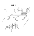
- FIG. 1 Illustrated in FIG. 1 is a non-destructive test system 10 in accordance with a preferred embodiment of the present invention.
- the system includes a current transformer 12 for generating a current flow between a first contact 14 and a second contact 16 secured to a test part 18.
- the contacts are copper stripping secured to the test part with bolts through conductive holes in the test part 18.
- a variac 20 is provided at the input to the transformer 12.
- the variac 20 converts an input supply 22 voltage to an output supply to the transformer 12.
- thermal camera 30 typically an infrared camera, can be provided to a display device 32, such as a computer, so that a real time image of the test part 18 can be viewed and the flaws directly identified.
- the input supply 22 that drives the transformer is an ordinary 110 volt rms alternating current supply.
- the system can be configured to operate using any input supply 22.
- the output of the current transformer is a seven ampere, two volt, sixty hertz supply.
- the current flow will be concentrated near the surface of the conductive material where flaws are most likely to exist.
- a direct current supply is desired, this can be achieved by utilizing a direct current supply 22 or by employing a suitable conversion device such as a rectifying bridge circuit.
- the seven ampere current is exemplary and that suitable current levels for testing different types of test parts can be readily determined by those of ordinary skill.
- the current supply should be high enough to cause rapid ohmic heating so that localized areas of increase heat, i.e., hot spots, and lower heat, i.e., cold shadows, can be identified.
- a particularly suitable application for the system and method of the present invention is in testing composite skin structures of airplanes.
- These composite skin structures typically contain a conductive mesh, such as an expanded aluminum mesh, that is laminated over a non-conductive graphite core.
- the conductive mesh serves to distribute the voltage, and thus the heat, of lightning strikes over a wide surface area of the airplane thus reducing the likelihood of localized damage to the composite skin structure from the lightning strike.
- the first and second contacts 14, 16 are secured to the segment of the airplane.
- the contacts are diverter strips or conductive fasteners provided on the composite skin structure. Cables are connected from the output of the transformer 12 to the conductive fasteners and the current is induced across the conductive mesh of the composite skin structure.
- Areas of delamination of the aluminum mesh from the graphite core can be identified by applying the current for a period of time and then observing the thermal image when the current is removed and as the part cools. Heat will dissipate more slowly in the areas of delamination, because it cannot be readily transferred to the underlying graphite layer, and thus will appear as hot spots on the thermal image.
- the thermal camera 30 used is the ThermaCAM® SC1000 camera with a standard 25 millimeter lens, supplied by FLIR Systems, Inc., www.flir.com.
- the output of the thermal camera can be displayed in real-time on a computer 32 or other display device or can be recorded for later playback.
- the raw output of the thermal camera can be recorded on video tape or can be captured by an image processing device.
- the image provided is that of the entire section of the composite skin structure being tested, rather than simply an output level displayed on an oscilloscope, a large surface area can be tested and the location of the discontinuity can still be readily identified from the cold shadow.
- the camera assembly 30 includes an additional camera provided for capturing a visual image of the test part.
- an additional camera provided for capturing a visual image of the test part.
- digital images captured from the thermal camera and visual camera can be overlayed on top of each other by making one of the images transparent.
- the thermal camera can toggle between a thermal image and a visual image of the test part thereby making identification of defects in the part easier.
- the computer 32 also preferably includes software to overlay the thermal and/or visual images with a CAD drawing of the test part.
- a digital thermal image is obtained from the thermal camera
- this can be overlayed, using the image processing device, onto a computer-aided design or other digital drawing of the test part.
- Another suitable application for the system of the present invention is for locating cracks in a metal sheet such as a titanium sheet.
- a metal sheet such as a titanium sheet.
- cracks in the sheet manifest themselves thermally as areas of localized heat increases such as at the terminus points of a crack running perpendicular to the current flow.
- defects are anomalous areas of higher heat.
- the integrity of the weld can be tested using the system of the present invention.
- the metal structure brazed to the metal sheet will operate as a heat sink. This will be observed as a cold shadow in a thermal image of the side of the metal sheet opposite the metal structure. Flaws in the integrity of the brazing will appear as hot spots in the cold shadow areas.
- the system of the current invention can be implemented utilizing at least to some extent, test equipment already existing in many test facilities.
- many test facilities utilize magnetic particle test machines to detect cracks in ferrous metal parts. These machines apply a large current across a ferrous metal test part that is placed in a suspension of magnetic material. Magnetic flux densities increase at areas of cracks and thus the magnetic material congregates at these locations.
- liquid crystal thermography can be used to observe the heat patterns of the test part subject to the ohmic heating.
- liquid crystal thermographic sheets can be applied to the test part, such as by vacuum attachment, to provide a low cost detector. As current is supplied across the part, areas of localized heating will be observed as hot spots on the liquid crystal sheets. Depending on the range of temperature variation in the part under test, multiple liquid crystal sheet may need to be bonded together to provide a sufficient range of temperature variation to provide adequate testing.
Landscapes
- Physics & Mathematics (AREA)
- Health & Medical Sciences (AREA)
- Life Sciences & Earth Sciences (AREA)
- Chemical & Material Sciences (AREA)
- Analytical Chemistry (AREA)
- Biochemistry (AREA)
- General Health & Medical Sciences (AREA)
- General Physics & Mathematics (AREA)
- Immunology (AREA)
- Pathology (AREA)
- Investigating Or Analyzing Materials Using Thermal Means (AREA)
- Investigating Or Analyzing Materials By The Use Of Electric Means (AREA)
Abstract
Description
Claims (15)
- A system for detecting thermal anomalies in a test part, comprising:a first contact secured at a first location on the test part;a second contact secured at a second location on the test part;a current supplying means for supplying a current between said first and said second contacts through said test part; anda detecting means for detecting a thermal image of the test part.
- A system according to claim 1 wherein:said current supplying means comprise current source; andsaid detecting means comprise a camera.
- The system of claim 2, wherein the current source is provided by a current transformer.
- The system of claim 3, wherein the current transformer supplies an alternating current of between 5 and 8 amperes.
- The system of claim 3, wherein the current transformer supplies a direct current of between 5 and 8 amperes.
- The system according to any of claims 1-5, further comprising a video display device for displaying the thermal image of the test part.
- The system of claim 6, wherein the camera also detects a visual image of the test part.
- The system of claim 7, further comprising an image processor for overlaying said thermal image on said visual image of the test part.
- The system of claim 7, further comprising an image processor for overlaying said thermal image of said test part onto a computer-aided design (CAD) drawing of the test part.
- The system according to any of claims 1-9, wherein the detecting means is a first liquid crystal sheet attached to the test part.
- The system of claim 10, wherein said first liquid crystal sheet is attached to the test part by vacuum.
- The system of claim 10 or 11, wherein at least one second additional liquid crystal sheet, having a different temperature sensitivity than said first sheet, is also attached to the test part.
- The system according to any of claims 1-12, wherein said current supply means is a magnetic particle machine.
- A method of detecting thermal anomalies in a test part, comprising the steps of:passing an electrical current through a test part to cause ohmic heating of the test part; anddetecting a thermal image of the test part.
- The method of claim 14, using a system according to any of claims 1 - 14.
Priority Applications (1)
| Application Number | Priority Date | Filing Date | Title |
|---|---|---|---|
| EP09015337A EP2175264A3 (en) | 2002-12-19 | 2003-11-21 | Thermographic method of detecting delamination in a composite part using ohmic heating by applying an electric current through the composite part itself |
Applications Claiming Priority (2)
| Application Number | Priority Date | Filing Date | Title |
|---|---|---|---|
| US322512 | 2002-12-19 | ||
| US10/322,512 US20040120383A1 (en) | 2002-12-19 | 2002-12-19 | Non-destructive testing system and method using current flow thermography |
Publications (2)
| Publication Number | Publication Date |
|---|---|
| EP1431754A2 true EP1431754A2 (en) | 2004-06-23 |
| EP1431754A3 EP1431754A3 (en) | 2004-09-01 |
Family
ID=32393020
Family Applications (2)
| Application Number | Title | Priority Date | Filing Date |
|---|---|---|---|
| EP03078669A Withdrawn EP1431754A3 (en) | 2002-12-19 | 2003-11-21 | Thermographic system and method using ohmic heating of the test part by applying an electric current through the test part itself |
| EP09015337A Withdrawn EP2175264A3 (en) | 2002-12-19 | 2003-11-21 | Thermographic method of detecting delamination in a composite part using ohmic heating by applying an electric current through the composite part itself |
Family Applications After (1)
| Application Number | Title | Priority Date | Filing Date |
|---|---|---|---|
| EP09015337A Withdrawn EP2175264A3 (en) | 2002-12-19 | 2003-11-21 | Thermographic method of detecting delamination in a composite part using ohmic heating by applying an electric current through the composite part itself |
Country Status (2)
| Country | Link |
|---|---|
| US (1) | US20040120383A1 (en) |
| EP (2) | EP1431754A3 (en) |
Cited By (5)
| Publication number | Priority date | Publication date | Assignee | Title |
|---|---|---|---|---|
| WO2007136264A1 (en) * | 2006-05-24 | 2007-11-29 | Stichting Materials Innovation Institute (M2I) | Non-destructive testing of composite structures |
| EP1987945A1 (en) * | 2007-05-04 | 2008-11-05 | Sgl Carbon Ag | Semifinished product for the manufacture of structural parts from fiber-reinforced composites |
| CN101116620B (en) * | 2006-08-03 | 2011-07-06 | Ge医疗系统以色列有限公司 | Method and apparatus for reducing polarization within an imaging device |
| EP2428795A1 (en) * | 2010-09-14 | 2012-03-14 | Siemens Aktiengesellschaft | Apparatus and method for automatic inspection of through-holes of a component |
| CN114397322A (en) * | 2021-11-26 | 2022-04-26 | 广东电网有限责任公司阳江供电局 | Heat dissipation index measuring method, system and device based on shadow compensation |
Families Citing this family (21)
| Publication number | Priority date | Publication date | Assignee | Title |
|---|---|---|---|---|
| US7425093B2 (en) * | 2003-07-16 | 2008-09-16 | Cabot Corporation | Thermography test method and apparatus for bonding evaluation in sputtering targets |
| US20050207468A1 (en) * | 2004-03-16 | 2005-09-22 | Mccullough Robert W | Inductively heated transient thermography method and apparatus for the detection of flaws |
| US7654734B2 (en) * | 2005-05-10 | 2010-02-02 | General Electric Company | Methods and devices for evaluating the thermal exposure of a metal article |
| US20100171518A1 (en) * | 2008-12-16 | 2010-07-08 | University Of New Brunswick | Method and apparatus for non-destructive detection of defects in composite laminate structures |
| DE102010027072A1 (en) * | 2010-07-13 | 2012-01-19 | Prüftechnik Dieter Busch AG | Method and system for predicting errors in components of rotating machines using thermography |
| US8745517B2 (en) * | 2011-06-09 | 2014-06-03 | Proto Labs, Inc. | Visual change cue for communicating manufacturing issues of a custom part |
| JP5469653B2 (en) * | 2011-12-12 | 2014-04-16 | 本田技研工業株式会社 | Nondestructive inspection system |
| US9706140B2 (en) | 2013-12-18 | 2017-07-11 | United Technologies Corporation | Natural resolution processing for LWIR images |
| US9832396B2 (en) | 2013-12-18 | 2017-11-28 | United Technologies Corporation | Composite image processing for LWIR images using geometric features |
| GB2528044B (en) | 2014-07-04 | 2018-08-22 | Arc Devices Ni Ltd | Non-touch optical detection of vital signs |
| US9854973B2 (en) | 2014-10-25 | 2018-01-02 | ARC Devices, Ltd | Hand-held medical-data capture-device interoperation with electronic medical record systems |
| DE102015203547A1 (en) * | 2015-02-27 | 2016-09-01 | Siemens Aktiengesellschaft | Non-destructive detection of faults in stator windings and device |
| US10506926B2 (en) | 2017-02-18 | 2019-12-17 | Arc Devices Limited | Multi-vital sign detector in an electronic medical records system |
| US10492684B2 (en) | 2017-02-21 | 2019-12-03 | Arc Devices Limited | Multi-vital-sign smartphone system in an electronic medical records system |
| US10602987B2 (en) | 2017-08-10 | 2020-03-31 | Arc Devices Limited | Multi-vital-sign smartphone system in an electronic medical records system |
| US10569894B2 (en) | 2017-10-16 | 2020-02-25 | Rohr, Inc. | Locating an aperture based on a signature of an embedded conductive element |
| US10485431B1 (en) | 2018-05-21 | 2019-11-26 | ARC Devices Ltd. | Glucose multi-vital-sign system in an electronic medical records system |
| US11504014B2 (en) | 2020-06-01 | 2022-11-22 | Arc Devices Limited | Apparatus and methods for measuring blood pressure and other vital signs via a finger |
| CN113804727B (en) * | 2021-08-30 | 2022-06-14 | 电子科技大学 | A Defect Reconstruction Method for Eddy Current Thermal Imaging Based on Electrical Impedance Imaging |
| ES2951300A1 (en) * | 2022-03-14 | 2023-10-19 | Univ Rey Juan Carlos | METHOD FOR MONITORING THE STRUCTURAL HEALTH OF CONTINUOUS FIBER COMPOSITE MATERIALS THROUGH RESISTIVE HEATING (Machine-translation by Google Translate, not legally binding) |
| US12495977B2 (en) | 2022-06-03 | 2025-12-16 | Arc Devices Limited | Apparatus and methods for measuring blood pressure and other vital signs via a finger |
Family Cites Families (35)
| Publication number | Priority date | Publication date | Assignee | Title |
|---|---|---|---|---|
| US1327341A (en) * | 1918-04-13 | 1920-01-06 | Snead & Co Iron Works | Method of developing defects in metallic objects |
| US3020745A (en) * | 1958-11-13 | 1962-02-13 | Smith Corp A O | Method of flaw detection in a metal member |
| US3396335A (en) * | 1966-08-26 | 1968-08-06 | Circuit Res Company | Method of testing printed circuit conductors |
| US3439525A (en) * | 1966-12-28 | 1969-04-22 | Boeing Co | Nondestructive testing method using liquid crystals |
| US3681970A (en) * | 1970-03-09 | 1972-08-08 | G C Optronics Inc | Method of flaw detection using internal heating |
| US3952276A (en) * | 1974-02-21 | 1976-04-20 | Siemens Aktiengesellschaft | Fluid tight NTC high temperature sensor and method of producing same |
| JPS5853729A (en) * | 1981-09-25 | 1983-03-30 | Chisso Eng Kk | Method for checking performance of outer heat insulating layer of pipe |
| JPS59218967A (en) * | 1983-05-27 | 1984-12-10 | Fujitsu Ltd | Method for testing wiring pattern of printed circuit board |
| US4527909A (en) * | 1983-09-23 | 1985-07-09 | Conax Corporation | Sealed temperature probe |
| JPH01296785A (en) * | 1988-05-24 | 1989-11-30 | Fujitsu Ltd | Picture superimposing device |
| US5089700A (en) * | 1990-01-30 | 1992-02-18 | Amdata, Inc. | Apparatus for infrared imaging inspections |
| JPH05203596A (en) * | 1991-05-31 | 1993-08-10 | Maeda Corp | How to manage concrete structures |
| US5562345A (en) * | 1992-05-05 | 1996-10-08 | The United States Of America As Represented By The Administrator Of The National Aeronautics And Space Administration | Method and apparatus for thermographically and quantitatively analyzing a structure for disbonds and/or inclusions |
| US5275489A (en) * | 1992-10-19 | 1994-01-04 | General Electric Company | Apparatus and method for inspecting an open-face cell structure bonded to a substrate |
| US5376793A (en) * | 1993-09-15 | 1994-12-27 | Stress Photonics, Inc. | Forced-diffusion thermal imaging apparatus and method |
| JP2858220B2 (en) * | 1994-09-13 | 1999-02-17 | 川惣電機工業株式会社 | Temperature sensor element in temperature measuring device |
| US5504017A (en) * | 1994-12-20 | 1996-04-02 | Advanced Micro Devices, Inc. | Void detection in metallization patterns |
| US5709469A (en) * | 1995-03-13 | 1998-01-20 | The United States Of America As Represented By The Secretary Of The Air Force | Process for testing integrity of bonds between epoxy patches and aircraft structural materials |
| US5749656A (en) * | 1995-08-11 | 1998-05-12 | General Motors Corporation | Thermal probe assembly with mold-over crimp sensor packaging |
| US5818951A (en) * | 1995-10-13 | 1998-10-06 | Infrared Service Corporation | Methods and related apparatus for generating thermographic survey images |
| US5711603A (en) * | 1996-10-30 | 1998-01-27 | United Technologies Corporation | Nondestructive testing: transient depth thermography |
| US6000844A (en) * | 1997-03-04 | 1999-12-14 | The United States Of America As Represented By The Administrator Of The National Aeronautics And Space Administration | Method and apparatus for the portable identification of material thickness and defects using spatially controlled heat application |
| US6111424A (en) * | 1997-09-04 | 2000-08-29 | Lucent Technologies Inc. | Testing method and apparatus for flat panel displays using infrared imaging |
| JP2001066271A (en) * | 1999-08-27 | 2001-03-16 | Ebara Corp | Method and apparatus for inspecting spot welds of pump impeller |
| US6595684B1 (en) * | 1999-11-03 | 2003-07-22 | Northrop Grumman Corporation | System and method for evaluating a structure |
| US7724925B2 (en) * | 1999-12-02 | 2010-05-25 | Thermal Wave Imaging, Inc. | System for generating thermographic images using thermographic signal reconstruction |
| US6751342B2 (en) * | 1999-12-02 | 2004-06-15 | Thermal Wave Imaging, Inc. | System for generating thermographic images using thermographic signal reconstruction |
| US6667761B1 (en) * | 2000-04-14 | 2003-12-23 | Imaging & Sensing Technology Corporation | Instrument visualization system |
| JP4016627B2 (en) * | 2000-11-22 | 2007-12-05 | 株式会社デンソー | Temperature sensor |
| US6399949B1 (en) * | 2000-12-22 | 2002-06-04 | General Electric Company | System and method for detecting debonding in rubber coated rolls |
| DE10111336B4 (en) * | 2001-03-08 | 2008-02-14 | Heraeus Electro-Nite International N.V. | Sensor, in particular temperature sensor, with a measuring resistor |
| US6676785B2 (en) * | 2001-04-06 | 2004-01-13 | Ebert Composites Corporation | Method of clinching the top and bottom ends of Z-axis fibers into the respective top and bottom surfaces of a composite laminate |
| JP2003234203A (en) * | 2002-02-07 | 2003-08-22 | Denso Corp | Manufacturing method of temperature sensor |
| US6712502B2 (en) * | 2002-04-10 | 2004-03-30 | The United States Of America As Represented By The Administrator Of The National Aeronautics And Space Administration | Synchronized electronic shutter system and method for thermal nondestructive evaluation |
| US20030219059A1 (en) * | 2002-05-23 | 2003-11-27 | Scott William R. | Thermographic system and method of operation thereof having composite implants |
-
2002
- 2002-12-19 US US10/322,512 patent/US20040120383A1/en not_active Abandoned
-
2003
- 2003-11-21 EP EP03078669A patent/EP1431754A3/en not_active Withdrawn
- 2003-11-21 EP EP09015337A patent/EP2175264A3/en not_active Withdrawn
Cited By (9)
| Publication number | Priority date | Publication date | Assignee | Title |
|---|---|---|---|---|
| WO2007136264A1 (en) * | 2006-05-24 | 2007-11-29 | Stichting Materials Innovation Institute (M2I) | Non-destructive testing of composite structures |
| CN101116620B (en) * | 2006-08-03 | 2011-07-06 | Ge医疗系统以色列有限公司 | Method and apparatus for reducing polarization within an imaging device |
| EP1987945A1 (en) * | 2007-05-04 | 2008-11-05 | Sgl Carbon Ag | Semifinished product for the manufacture of structural parts from fiber-reinforced composites |
| WO2008135559A1 (en) * | 2007-05-04 | 2008-11-13 | Sgl Carbon Ag | Semifinished product for producing components from fibre-reinforced composite materials |
| EP2428795A1 (en) * | 2010-09-14 | 2012-03-14 | Siemens Aktiengesellschaft | Apparatus and method for automatic inspection of through-holes of a component |
| WO2012035045A1 (en) | 2010-09-14 | 2012-03-22 | Siemens Aktiengesellschaft | Apparatus and method for automatic inspection of through-holes of a component |
| US9310312B2 (en) | 2010-09-14 | 2016-04-12 | Siemens Aktiengesellschaft | Apparatus and method for automatic inspection of through-holes of a component |
| CN114397322A (en) * | 2021-11-26 | 2022-04-26 | 广东电网有限责任公司阳江供电局 | Heat dissipation index measuring method, system and device based on shadow compensation |
| CN114397322B (en) * | 2021-11-26 | 2024-02-06 | 广东电网有限责任公司阳江供电局 | Heat dissipation index measurement method, system and device based on shadow compensation |
Also Published As
| Publication number | Publication date |
|---|---|
| US20040120383A1 (en) | 2004-06-24 |
| EP1431754A3 (en) | 2004-09-01 |
| EP2175264A2 (en) | 2010-04-14 |
| EP2175264A3 (en) | 2010-06-16 |
Similar Documents
| Publication | Publication Date | Title |
|---|---|---|
| EP2175264A2 (en) | Thermographic method of detecting delamination in a composite part using ohmic heating by applying an electric current through the composite part itself | |
| Yi et al. | Evaluation of debonding in CFRP-epoxy adhesive single-lap joints using eddy current pulse-compression thermography | |
| US8220991B2 (en) | Electromagnetically heating a conductive medium in a composite aircraft component | |
| Wilson et al. | Pulsed eddy current thermography: system development and evaluation | |
| He et al. | Dynamic scanning electromagnetic infrared thermographic analysis based on blind source separation for industrial metallic damage evaluation | |
| US20050207468A1 (en) | Inductively heated transient thermography method and apparatus for the detection of flaws | |
| CA2074811C (en) | Method for inspecting density of carbon fibers in a substrate by infrared imaging | |
| WO2015056790A1 (en) | Cracking detection system and cracking detection method | |
| Misokefalou et al. | Non-destructive testing for quality control in automotive industry | |
| Cheng et al. | Stainless steel weld defect detection using pulsed inductive thermography | |
| Wu et al. | Weld crack detection based on region electromagnetic sensing thermography | |
| Miao et al. | Novel interventional electromagnetic thermography for subsurface defect detection | |
| Lu et al. | Defects inspection of the solder bumps using self reference technology in active thermography | |
| Vrana et al. | Induction and conduction thermography: Optimizing the electromagnetic excitation towards application | |
| Smeets et al. | Characterization of impact damage patterns in composite aerospace structures using augmented thermal signal reconstruction | |
| Zhu et al. | Nondestructive testing for multi-layer metal-metal bonded structure by using inductive lock-in thermograhy | |
| McGovern et al. | Assessment of ultrasonic welds using pulsed infrared thermography | |
| Zhou et al. | Optical flow amplitude-based method for detection and quantitative evaluation of impact damage in CFRP | |
| US10481116B2 (en) | High resolution inspection device for casting defects using IR imaging | |
| US20200173944A1 (en) | Method for non-destructive testing of components produced from carbon fiber reinforced composite materials | |
| Balaji et al. | Induction thermography for non-destructive evaluation of adhesive bonds | |
| Ezato et al. | Non-destructive testing of CFC monoblock divertor mock-ups | |
| Courtois et al. | Health monitoring of Tore-Supra toroidal pump limiter using lock-in thermography | |
| Carreon | Thermoelectric detection of hard alpha inclusion in Ti–6Al–4V by magnetic sensing | |
| Liu et al. | Evaluation of package defects by thermal imaging techniques |
Legal Events
| Date | Code | Title | Description |
|---|---|---|---|
| PUAI | Public reference made under article 153(3) epc to a published international application that has entered the european phase |
Free format text: ORIGINAL CODE: 0009012 |
|
| AK | Designated contracting states |
Kind code of ref document: A2 Designated state(s): AT BE BG CH CY CZ DE DK EE ES FI FR GB GR HU IE IT LI LU MC NL PT RO SE SI SK TR |
|
| AX | Request for extension of the european patent |
Extension state: AL LT LV MK |
|
| PUAL | Search report despatched |
Free format text: ORIGINAL CODE: 0009013 |
|
| AK | Designated contracting states |
Kind code of ref document: A3 Designated state(s): AT BE BG CH CY CZ DE DK EE ES FI FR GB GR HU IE IT LI LU MC NL PT RO SE SI SK TR |
|
| AX | Request for extension of the european patent |
Extension state: AL LT LV MK |
|
| 17P | Request for examination filed |
Effective date: 20041203 |
|
| AKX | Designation fees paid |
Designated state(s): DE FR GB |
|
| 17Q | First examination report despatched |
Effective date: 20050629 |
|
| RAP1 | Party data changed (applicant data changed or rights of an application transferred) |
Owner name: THE BOEING COMPANY |
|
| STAA | Information on the status of an ep patent application or granted ep patent |
Free format text: STATUS: THE APPLICATION HAS BEEN WITHDRAWN |
|
| 18W | Application withdrawn |
Effective date: 20091211 |