EP1431744B1 - Evaluation of particulate material - Google Patents
Evaluation of particulate material Download PDFInfo
- Publication number
- EP1431744B1 EP1431744B1 EP02080446A EP02080446A EP1431744B1 EP 1431744 B1 EP1431744 B1 EP 1431744B1 EP 02080446 A EP02080446 A EP 02080446A EP 02080446 A EP02080446 A EP 02080446A EP 1431744 B1 EP1431744 B1 EP 1431744B1
- Authority
- EP
- European Patent Office
- Prior art keywords
- batch
- fraction
- seed
- seeds
- plant product
- Prior art date
- Legal status (The legal status is an assumption and is not a legal conclusion. Google has not performed a legal analysis and makes no representation as to the accuracy of the status listed.)
- Expired - Lifetime
Links
- 239000011236 particulate material Substances 0.000 title abstract description 28
- 238000011156 evaluation Methods 0.000 title description 5
- 238000005303 weighing Methods 0.000 claims abstract description 10
- 238000000034 method Methods 0.000 claims description 20
- 238000000926 separation method Methods 0.000 claims description 5
- 239000000463 material Substances 0.000 abstract description 19
- 239000002245 particle Substances 0.000 description 39
- 241000196324 Embryophyta Species 0.000 description 36
- 238000013480 data collection Methods 0.000 description 11
- 230000003287 optical effect Effects 0.000 description 10
- 239000000428 dust Substances 0.000 description 8
- 238000005259 measurement Methods 0.000 description 5
- 235000013339 cereals Nutrition 0.000 description 4
- 238000003306 harvesting Methods 0.000 description 4
- 230000000717 retained effect Effects 0.000 description 4
- 239000008187 granular material Substances 0.000 description 3
- 230000000452 restraining effect Effects 0.000 description 3
- 230000005484 gravity Effects 0.000 description 2
- 239000002184 metal Substances 0.000 description 2
- 210000001364 upper extremity Anatomy 0.000 description 2
- 235000014698 Brassica juncea var multisecta Nutrition 0.000 description 1
- 235000006008 Brassica napus var napus Nutrition 0.000 description 1
- 240000000385 Brassica napus var. napus Species 0.000 description 1
- 235000006618 Brassica rapa subsp oleifera Nutrition 0.000 description 1
- 235000004977 Brassica sinapistrum Nutrition 0.000 description 1
- 244000020518 Carthamus tinctorius Species 0.000 description 1
- 235000003255 Carthamus tinctorius Nutrition 0.000 description 1
- 244000068988 Glycine max Species 0.000 description 1
- 235000010469 Glycine max Nutrition 0.000 description 1
- 244000020551 Helianthus annuus Species 0.000 description 1
- 235000003222 Helianthus annuus Nutrition 0.000 description 1
- 240000005979 Hordeum vulgare Species 0.000 description 1
- 235000007340 Hordeum vulgare Nutrition 0.000 description 1
- 240000007594 Oryza sativa Species 0.000 description 1
- 235000007164 Oryza sativa Nutrition 0.000 description 1
- 244000062793 Sorghum vulgare Species 0.000 description 1
- 108700019146 Transgenes Proteins 0.000 description 1
- 235000021307 Triticum Nutrition 0.000 description 1
- 244000098338 Triticum aestivum Species 0.000 description 1
- 240000008042 Zea mays Species 0.000 description 1
- 235000005824 Zea mays ssp. parviglumis Nutrition 0.000 description 1
- 235000002017 Zea mays subsp mays Nutrition 0.000 description 1
- 238000004458 analytical method Methods 0.000 description 1
- 238000009395 breeding Methods 0.000 description 1
- 230000001488 breeding effect Effects 0.000 description 1
- 238000004140 cleaning Methods 0.000 description 1
- 239000000356 contaminant Substances 0.000 description 1
- 235000005822 corn Nutrition 0.000 description 1
- 238000009795 derivation Methods 0.000 description 1
- 239000012530 fluid Substances 0.000 description 1
- 239000012535 impurity Substances 0.000 description 1
- 238000003780 insertion Methods 0.000 description 1
- 230000037431 insertion Effects 0.000 description 1
- 230000008774 maternal effect Effects 0.000 description 1
- 235000019713 millet Nutrition 0.000 description 1
- 238000003976 plant breeding Methods 0.000 description 1
- 238000012545 processing Methods 0.000 description 1
- 235000009566 rice Nutrition 0.000 description 1
- 230000001568 sexual effect Effects 0.000 description 1
- 239000010902 straw Substances 0.000 description 1
Images

Classifications
-
- G—PHYSICS
- G01—MEASURING; TESTING
- G01N—INVESTIGATING OR ANALYSING MATERIALS BY DETERMINING THEIR CHEMICAL OR PHYSICAL PROPERTIES
- G01N5/00—Analysing materials by weighing, e.g. weighing small particles separated from a gas or liquid
- G01N5/04—Analysing materials by weighing, e.g. weighing small particles separated from a gas or liquid by removing a component, e.g. by evaporation, and weighing the remainder
-
- G—PHYSICS
- G01—MEASURING; TESTING
- G01N—INVESTIGATING OR ANALYSING MATERIALS BY DETERMINING THEIR CHEMICAL OR PHYSICAL PROPERTIES
- G01N15/00—Investigating characteristics of particles; Investigating permeability, pore-volume or surface-area of porous materials
- G01N15/10—Investigating individual particles
- G01N15/14—Optical investigation techniques, e.g. flow cytometry
- G01N15/1456—Optical investigation techniques, e.g. flow cytometry without spatial resolution of the texture or inner structure of the particle, e.g. processing of pulse signals
-
- G—PHYSICS
- G01—MEASURING; TESTING
- G01N—INVESTIGATING OR ANALYSING MATERIALS BY DETERMINING THEIR CHEMICAL OR PHYSICAL PROPERTIES
- G01N15/00—Investigating characteristics of particles; Investigating permeability, pore-volume or surface-area of porous materials
- G01N15/02—Investigating particle size or size distribution
- G01N15/0205—Investigating particle size or size distribution by optical means
- G01N2015/0238—Single particle scatter
-
- G—PHYSICS
- G01—MEASURING; TESTING
- G01N—INVESTIGATING OR ANALYSING MATERIALS BY DETERMINING THEIR CHEMICAL OR PHYSICAL PROPERTIES
- G01N15/00—Investigating characteristics of particles; Investigating permeability, pore-volume or surface-area of porous materials
- G01N15/10—Investigating individual particles
- G01N15/14—Optical investigation techniques, e.g. flow cytometry
- G01N2015/1486—Counting the particles
Definitions
- This invention relates to evaluation of particulate material and is especially concerned with evaluation of seed in a batch of plant product.
- a major goal is to find genotypes that have a high seed yield. Breeders often have to analyse the seed yield of large populations of plants with different genotypes, obtained for example through sexual crossing of parental lines. Molecular breeders, who create variability by insertion of transgenes in a plant species, also have to cope with large plant populations of which the seed yield needs to be assessed. Tools for fast, accurate and efficient measurement of seed yield are a necessity for the plant breeding industry.
- the mature seeds are weighed and counted, so that the total mature seed weight (otherwise referred to as the yield) which is an important parameter for breeders, can be derived as well as the average weight per mature seed which gives a value for comparison with for example, the thousand kernel weight that is commonly used as an important parameter by breeders.
- Instruments used for conducting these measurements in such a procedure include balances for measuring seed weight and seed counters for counting the number of seeds, all of which exist in different commercially available types.
- One type of seed counter comprises an inlet for a batch of seed, a system that allows the seeds to drop one by one, and a system to detect each particle of a defined size that passes in front of an optical detector.
- Instruments for cleaning the seeds also exist in different commercially available types. Some are based on the passage of seeds over sets of shaking sieves with different mesh size, until seeds of the right particle size are retained on one of those sieves.
- Other instruments are based on the differential aerodynamic and/or gravity properties of seeds versus contaminants in a fluid flow, usually a stream of air. Discrimination of matured versus immature seeds can also be done based on the principle of differential aerodynamic/gravity properties.
- US patent number US 4,588,091 in the name of Franklin J. Wade, describes an apparatus for the measurement of the quality parameters of granular materials, which apparatus includes a loader assembly which delivers precise volume samples of granular material to a meter assembly which measures the moisture content. The apparatus also includes a sieve assembly which separates the samples into fractions according to kernel size. A scale assembly weighs the fractions and feeds this information to a computer which controls the apparatus and calculates the moisture content, density and percentage of foreign material contained in the granular material.
- British patent number GB1378715 describes an harvesting and/or processing machine, more especially a combine harvester, having at least one point at which products or material being lost is measured or at which damaged or faultily processed material, e.g. straw particles in the grain, is measured.
- the apparatus and method are used for separating and classifying agricultural products like grains. At least two measurement values such as throughput, yield and damage and/or wrongly transported material are indicated simultaneously or in time sequence. At a first measuring point the amount of particles in a multi-particle flow of the entire threshed material is measured in volume, weight or number per unit time or a fraction of such output is used as the measured amount. At least one other measuring point is provided for measuring the amount of lost, damaged or wrongly transported material in a multi-particle flow.
- the flows may be monitored by acousto-electric, capacitive or photoelectric transducers.
- a capacitive transducer the variations of the capacity by the falling grains are transmitted via high-frequency measuring bridges. Their signals are communicated to a comparison means, such as an electronic calculator, for calculating the ratios of the measured particulate flows.
- a fully digitalised measurement is proposed.
- the invention provides in one of its aspects apparatus for determining and recording characteristics of seed in a batch of plant product according to claim 1.
- Apparatus according to the invention is preferably constructed and arranged so that the inlet to the separator chamber, an outlet from the separator chamber for the first fraction, counter means and means for weighing the first fraction are arranged one above another so that the first fraction may be allowed to fall from the inlet to the weighing means.
- the apparatus is so constructed and arranged that particles may drop one by one from the inlet into the separator chamber.
- the first fraction follows an at least substantially linear line of passage from the inlet to the weighing means.
- the particulate material is allowed to fall through a vertically disposed passageway shaped to disrupt the falling particulate material as it reaches an entry port through which flow of gas may enter the separator chamber.
- the means for causing a flow of gas in the separator chamber of apparatus may take any suitable form for example a compressed gas supply may be utilised to blow the gas though the chamber, or fan means may be utilised to draw the gas through the chamber.
- the gas used is preferably air, in which case the fan means is preferred.
- the gas is caused to flow in the separator chamber at least somewhat across the line of passage of particulate material supplied to the separator chamber, whereby particles are borne to a lesser or greater degree from the line of passage.
- baffle means is provided within the separator chamber at a position from the line of passage commensurate with restraining particles of the second fraction from returning to the first fraction after separation.
- the separator chamber may include a chamber in which the second fraction is retained or alternatively may have a discharge opening through which the second fraction is evacuated from the separating chamber.
- the separator chamber is provided with a vent through which material such as dust or other plant residue may be evacuated from the separator chamber.
- the means for reading an identifier on the batch is preferably a bar code reader but may be any other suitable reader appropriate to the identifier employed.
- the particles of seed material are caused to drop one by one through the first and second counter means so they may be counted.
- Any counting means capable of detecting the particles may be employed for example optical or capacitance counters. We prefer to employ optical counting means or capacitance counting.
- Apparatus according to the invention may also comprise means for optical assessment of grain size of particles in the first fraction.
- Apparatus according to the invention may also comprise means for applying the identifier to the batch of particulate material.
- the means for reading the identifier, the first and second counting means and the means for weighing the first fraction each provide output in digital form. These are integrated by use of software in a computer device and fed therefrom to the database.
- the database may be manipulated to inspect and compare data to determine various characteristics such as the amount of particles in the first fraction, the average weight of particles in the first fraction and the ratio of particles in the first fraction to the number of particles in the second fraction.
- Apparatus according to the invention permits derivation of data about the seed without human intervention other than perhaps initial feeding of the seed to the inlet and / or removal of particles from the apparatus. It may be used for a variety of purposes and is especially useful for evaluation of mature seeds in a batch of material obtained by harvesting one or more plants.
- the apparatus provides an integrated automatic process for separating seed in a batch harvested from one or more plants from detritus, and separating matured seed from immature seed.
- desired data about key parameters of interest to the plant breeder such as seed yield, average seed weight and ratio of matured to immature seed in the batch.
- the invention provides in another of its aspects a process for evaluating and recording characteristics of seed in a batch of plant product according to claim 2.
- the computer database compiled by subjecting batches of plant product to a process as aforesaid may be interrogated and enables rapid comparison of characteristics from a multitude of different plants and thus permits rapid determination of seeds from which further plants may be derived which yield seeds having desired characteristics.
- the invention provides in another of its aspects a process for comparing one or more of the characteristics of seed yield, average seed weight and / or ratio of mature versus improperly matured seeds in a batch of plant product with corresponding characteristics of other batches of plant product, in which a computer database compiled by subjecting batches of plant product to a process according to the last preceding paragraph but one is interrogated concerning said one or more characteristics.
- the example instruments provide means for determining and recording characteristics of seed in a batch of plant product.
- the first example instrument comprises a separator chamber (10) having an inlet (12) through which a batch of seed may be supplied to the separator chamber, an outlet (14) from the separator, first counter means (16), second counter means (18) and a balance (20). These are arranged one above another.
- the first counter means has a vibratory feeder device to separate the particulate material into individual particles, so that they pass this and the lower counter one by one.
- a fan (not shown) is provided for drawing a flow of air through the separator chamber (10) via the inlet (12) and generally from left to right as viewed in Figure 1 to separate seed passing through the separator chamber into a first fraction consisting essentially of heavier particulate material and a second fraction consisting essentially of lighter material.
- the instrument is so constructed and arranged that in use, particles may drop one by one past the counter (18), into the separator (10) and so that those of the first fraction may fall from the inlet (12) to the balance (20) in an at least substantially vertical, linear line of passage.
- the flow of air drawn through the separator chamber is such that particles are borne to a lesser or greater degree from the line of passage.
- Baffle means in the form of vertically extending metal plates (22, 24) is provided within the separator chamber at a position from the line of passage commensurate with restraining lighter particles from returning to the first fraction after separation.
- the separator chamber (10) includes a sub-chamber (26) in which the second fraction is retained.
- a vent (28) is provided at an upper extremity of the separator chamber through extraneous matter such as dust or plant residue may be evacuated from the separator chamber.
- Each of the counters (16 and 18) comprises an optical counting means arranged to count particles falling past it.
- the first counting means (16) is provided for counting the particles in the first fraction and the second counting means (18) for counting particles of the particulate material in the batch.
- the counting means provide the results as a digital outputs (30, 32).
- the balance provides means for weighing the first fraction and also provides its result as a digital output (34).
- the instrument has a bar code reader (36) which provides means for reading an identifier in the form of a bar code on the batch of particulate material supplied to the inlet.
- the bar code reader is arranged to supply the identifier bar code as a digital output (38).
- the instrument also comprises means (not shown) for applying the identifier to the batch of particulate material.
- the various digital outputs (30, 32, 34, 38) are fed from the instrument to a data collection point (40) at which they are integrated by use of software in a computer device.
- the information derived is then supplied to a computer programmed to store data in prescribed format in a database from which it may be manipulated to afford comparison of characteristics of batches of particulate material.
- the second example instrument comprises a separator chamber (110) having an inlet (112) through which a batch of plant product may be supplied to the separator chamber, an outlet (114) from the separator, first counter means (116) second counter means (118) and a balance (120).
- the inlet (112), outlet (114), first counter means (116) and balance (120) are arranged one above another.
- Fan means (not shown) as employed in the first example instrument is provided for drawing a flow of air through the separator chamber (110) to separate particulate material passing through the separator chamber into a first fraction consisting essentially of heavier particulate material and a second fraction consisting essentially of lighter material.
- the instrument is so constructed and arranged that in use, particles may drop from the inlet (112) via a vibratory hopper and pass one by one, into the separator chamber (110) and so that those of the first fraction may fall from the inlet (112) to the balance (120) in an at least substantially vertical, linear line of passage.
- the air flow in the separator chamber serves to carry particles to a lesser or greater degree from the line of passage.
- Baffle means in the form of vertically extending metal plates (122, 124) is provided within the separator chamber at a position from the line of passage commensurate with restraining lighter particles from returning to the first fraction after separation.
- the separator chamber (110) includes a sub-chamber (126) defined by the baffle (122) and a wall (125) in which the second fraction is collected.
- Particles of the second fraction may then pass through a conduit (127) and fall past the second counter (118) and collect in a chamber (not shown).
- a second sub-chamber (142) defined by the wall (125) and an interior wall portion of the separator chamber, is provided into which a third fraction of the batch may pass.
- a vent (128) is provided at an upper extremity of the separator chamber through which extraneous matter such as dust may be evacuated from the separator chamber.
- Each of the counters (116 and 118) comprises an optical counting means arranged to count particles falling past it.
- the first counting means (116) is provided for counting the particles in the first fraction and the second counting means (118) for counting particles of the second fraction.
- the counting means each provide results as a digital output (130, 133).
- the balance provides means for weighing the first fraction and also provides its result as a digital output (134).
- the instrument has a bar code reader (136) which provides means for reading an identifier in the form of a bar code on the batch of particulate material supplied to the inlet.
- the bar code reader is arranged to supply the identifier bar code as a digital output (138).
- the instrument also comprises means (not shown) for applying the identifier to the batch of particulate material.
- the various digital outputs (130, 133, 134, 138) are fed from the instrument to a data collection point (140) at which they are integrated by use of software in a computer device.
- the information derived is then supplied to a computer programmed to store data in prescribed format in a database from which it may be manipulated to afford comparison of characteristics of batches of seed.
- the third example instrument comprises a separator chamber (210) having an inlet (212) through which a batch of plant product may be supplied via a vibratory hopper (not shown) to the separator chamber, an outlet (214) from the separator chamber, first counter means (216), second counter means (218) and a balance (220). These are arranged one above another.
- a fan (221) is provided for drawing a flow of air through the separator chamber (210) via an inlet port (223) and generally from left to right as viewed in Figure 3 to separate particulate material passing through the separator chamber into a first fraction consisting essentially of heavier particulate material and a second fraction consisting essentially of lighter material.
- the particulate material is allowed to fall through a vertically disposed passageway (225) shaped (227) to disrupt the passage of particles of falling material as they reach the entry port (223) through which flow of gas may enter the separator, being drawn through the separator chamber by the fan (221).
- Baffles (224, 226) and an internal wall (231) of the separator chamber are curved in such a way that air drawn through the chamber follows a somewhat sinusoidal path to one side of the passageway (225) as indicated by the arrows in Figure 3.
- the instrument is so constructed and arranged that in use, particles may drop one by one past the counter (218), into the separator (210) and so that those of the first fraction may fall from the inlet (212) to the balance (220) in an at least substantially vertical line of passage.
- the flow of air drawn through the separator chamber is such that particles are borne to a lesser or greater degree from the line of passage. Air flowing between the baffles (224, 226) restrains lighter particles from returning to the first fraction after separation.
- the separator chamber (210) includes a sub-chamber (228) in which the second fraction is retained.
- the air drawn out of the separator chamber by the fan (221 carries extraneous matter such as dust through the fan and out of the separator chamber.
- Each of the counters (216 and 218) comprises an optical counting means arranged to count particles falling past it.
- the first counting means (216) is provided for counting the particles in the first fraction and the second counting means (218) for counting particles of the particulate material in the batch.
- the counting means provide the results as digital outputs (not shown) in the same way as in the first example instrument.
- the balance provides means for weighing the first fraction and also provides its result as a digital output (not shown) as in the first example instrument.
- the instrument has a bar code reader (not shown) which provides means for reading an identifier in the form of a bar code on the batch of particulate material supplied to the inlet.
- the bar code reader is arranged to supply the identifier bar code as a digital output.
- the instrument also comprises means (not shown) for applying the identifier to the batch of particulate material.
- the various digital outputs are fed from the instrument to a data collection point at which they are integrated by use of software in a computer device.
- the information derived is then supplied to a computer programmed to store data in prescribed format in a database from which it may be manipulated to afford comparison of characteristics of batches of particulate material.
- the first example instrument was used to determine characteristics of a batch of seed harvested from a plant.
- the instrument applied a unique bar code to the batch, which was read by the bar code reader (36), which in turn sent its digital output (38) to the data collection point (40) thereby identifying the batch.
- the batch was automatically transferred seed by seed from the inlet (12) to the separator chamber (10). Air flowing in the separator chamber caused material supplied to the separator chamber to separate into a first fraction consisting essentially of mature seeds and a second fraction consisting essentially of immature seeds and a third fraction consisting of unwanted dust and other plant materials.
- the first fraction fell onto the balance where its total weight was measured and transferred as digital output (34).
- the second fraction was captured in the sub-chamber (26) and the third fraction was emitted from the exhaust (28). Seed falling past the counters (18, 16) was counted by the optical devices and the result supplied as digital outputs (30, 32) to the data collection point.
- the average weight of the seeds in the first fraction was determined and the data manipulated to determine the ratio of mature seeds in the batch to immature seeds in the batch.
- the results were sent to and recorded in a computer database in a prescribed format together with the batch identifier.
- the seed yield was derived from the balance output, the average seed weight was derived by taking the ratio of the seed yield to the number of mature seeds as assessed by the output of the first counter (16) and the ratio of mature seeds versus immature seeds is derived by taking the ratio of the output from the first counter (16) to the output from the second counter (18) minus the output of the first counter. Characteristics of seed yield, average seed weight and / or ratio of mature versus immature seeds in the batch were compared with corresponding characteristics of other batches of plant product assembled in the computer database.
- the second example instrument was used to determine characteristics of a batch of seed harvested from a plant.
- the instrument applied a unique bar code to the batch, which was read by the bar code reader (136), which in turn sent its digital output (138) to the data collection point (140) thereby identifying the batch.
- the batch was automatically transferred seed by seed from the inlet (112) to the separator chamber (110). Air flowing in the separator chamber caused material supplied to the separator chamber to separate into a first fraction consisting essentially of mature seeds, a second fraction consisting essentially of immature seeds and a third fraction consisting of unwanted dust and other plant materials.
- the first fraction fell onto the balance (120) where its total weight was measured and transferred as digital output (134).
- the second fraction was captured in the sub-chamber (126) and the third fraction was passed into the second sub-chamber from whence dust was exhausted via the exhaust (128). Seed falling past the counters (118, 116) was counted by the optical devices and the result supplied as digital outputs (130, 133) to the data collection point (140).
- the average weight of the seeds in the first fraction was determined and the data manipulated to determine the ratio of mature seeds in the batch to immature seeds in the batch.
- the results were sent to and recorded in a computer database in a prescribed format together with the batch identifier.
- the seed yield was derived from the balance output, the average seed weight was derived by taking the ratio of the seed yield to the number of mature seeds as assessed by the output of the first counter (116) and the ratio of mature seeds versus immature seeds was derived by taking the ratio of the output from the first counter (116) to the output from the second counter (118).
- the third example instrument was used in a substantially similar way to the first process to separate particulate material into a first fraction consisting essentially of mature seeds and a second fraction consisting essentially of immature seeds and a third fraction consisting of extraneous materials.
- the weight of the first fraction was measured and transferred as digital output.
- the second fraction was captured in the sub-chamber (228) and the third fraction was exhausted through the fan (221).
- seed falling past the counters (218, 216) was counted by the optical devices and the result supplied as digital outputs to the data collection point.
- the average weight of the seeds in the first fraction was determined and the data manipulated to determine the ratio of mature seeds in the batch to immature seeds in the batch.
- the results were sent to and recorded in a computer database in a prescribed format together with the batch identifier.
- the seed yield was derived from the balance output, the average seed weight was derived by taking the ratio of the seed yield to the number of mature seeds as assessed by the output of the first counter and the ratio of mature seeds versus immature seeds is derived by taking the ratio of the output from the first counter to the output from the second counter minus the output of the first counter.
- Characteristics of seed yield, average seed weight and / or ratio of mature versus immature seeds in the batch were compared with corresponding characteristics of other batches of plant product assembled in the computer database.
Landscapes
- Chemical & Material Sciences (AREA)
- Immunology (AREA)
- Physics & Mathematics (AREA)
- Health & Medical Sciences (AREA)
- Analytical Chemistry (AREA)
- Biochemistry (AREA)
- General Health & Medical Sciences (AREA)
- Life Sciences & Earth Sciences (AREA)
- Pathology (AREA)
- General Physics & Mathematics (AREA)
- Dispersion Chemistry (AREA)
- Pretreatment Of Seeds And Plants (AREA)
- Sorting Of Articles (AREA)
- Storage Of Harvested Produce (AREA)
- Sampling And Sample Adjustment (AREA)
- Silicon Compounds (AREA)
Abstract
Description
- This invention relates to evaluation of particulate material and is especially concerned with evaluation of seed in a batch of plant product.
- In breeding of plants cultivated for their seeds (also called seed crops) for example rice, wheat, barley, corn, soybean, canola, sunflower, millet and safflower, a major goal is to find genotypes that have a high seed yield. Breeders often have to analyse the seed yield of large populations of plants with different genotypes, obtained for example through sexual crossing of parental lines. Molecular breeders, who create variability by insertion of transgenes in a plant species, also have to cope with large plant populations of which the seed yield needs to be assessed. Tools for fast, accurate and efficient measurement of seed yield are a necessity for the plant breeding industry.
- It is one practice to evaluate seed produced by plants by a procedure which involves several steps. The seeds are physically separated from the plant, the harvest step, and then cleaned to remove non-seed remnants originating from the maternal plant and dust or other contaminating particles. Mature seeds are discriminated from improperly matured seeds (hereinafter "immature seeds"), e.g. seeds that are not completely filled. In most cases the ratio of mature seeds versus immature seeds is recorded as a parameter that is relevant for the breeders. The mature seeds are weighed and counted, so that the total mature seed weight (otherwise referred to as the yield) which is an important parameter for breeders, can be derived as well as the average weight per mature seed which gives a value for comparison with for example, the thousand kernel weight that is commonly used as an important parameter by breeders.
- Instruments used for conducting these measurements in such a procedure include balances for measuring seed weight and seed counters for counting the number of seeds, all of which exist in different commercially available types. One type of seed counter comprises an inlet for a batch of seed, a system that allows the seeds to drop one by one, and a system to detect each particle of a defined size that passes in front of an optical detector. Instruments for cleaning the seeds also exist in different commercially available types. Some are based on the passage of seeds over sets of shaking sieves with different mesh size, until seeds of the right particle size are retained on one of those sieves. Other instruments are based on the differential aerodynamic and/or gravity properties of seeds versus contaminants in a fluid flow, usually a stream of air. Discrimination of matured versus immature seeds can also be done based on the principle of differential aerodynamic/gravity properties.
- US patent number US 4,588,091, in the name of Franklin J. Wade, describes an apparatus for the measurement of the quality parameters of granular materials, which apparatus includes a loader assembly which delivers precise volume samples of granular material to a meter assembly which measures the moisture content. The apparatus also includes a sieve assembly which separates the samples into fractions according to kernel size. A scale assembly weighs the fractions and feeds this information to a computer which controls the apparatus and calculates the moisture content, density and percentage of foreign material contained in the granular material.
- British patent number GB1378715 describes an harvesting and/or processing machine, more especially a combine harvester, having at least one point at which products or material being lost is measured or at which damaged or faultily processed material, e.g. straw particles in the grain, is measured. The apparatus and method are used for separating and classifying agricultural products like grains. At least two measurement values such as throughput, yield and damage and/or wrongly transported material are indicated simultaneously or in time sequence. At a first measuring point the amount of particles in a multi-particle flow of the entire threshed material is measured in volume, weight or number per unit time or a fraction of such output is used as the measured amount. At least one other measuring point is provided for measuring the amount of lost, damaged or wrongly transported material in a multi-particle flow. The flows may be monitored by acousto-electric, capacitive or photoelectric transducers. For a capacitive transducer, the variations of the capacity by the falling grains are transmitted via high-frequency measuring bridges. Their signals are communicated to a comparison means, such as an electronic calculator, for calculating the ratios of the measured particulate flows. A fully digitalised measurement is proposed.
- Is one object of the present invention to provide improved apparatus for determining and recording characteristics of seed in a batch of plant product.
- It is another of the objects of this invention to provide an improved process for the evaluation of mature seeds in a batch of plant product.
- The invention provides in one of its aspects apparatus for determining and recording characteristics of seed in a batch of plant product according to claim 1.
- The word "comprising" where used herein is intended to encompass the notion of "including" and the notion of "consisting essentially of".
- Apparatus according to the invention is preferably constructed and arranged so that the inlet to the separator chamber, an outlet from the separator chamber for the first fraction, counter means and means for weighing the first fraction are arranged one above another so that the first fraction may be allowed to fall from the inlet to the weighing means. Preferably, the apparatus is so constructed and arranged that particles may drop one by one from the inlet into the separator chamber. Preferably the first fraction follows an at least substantially linear line of passage from the inlet to the weighing means. In one embodiment hereinafter described the particulate material is allowed to fall through a vertically disposed passageway shaped to disrupt the falling particulate material as it reaches an entry port through which flow of gas may enter the separator chamber.
The means for causing a flow of gas in the separator chamber of apparatus according to the invention may take any suitable form for example a compressed gas supply may be utilised to blow the gas though the chamber, or fan means may be utilised to draw the gas through the chamber. The gas used is preferably air, in which case the fan means is preferred. Preferably, the gas is caused to flow in the separator chamber at least somewhat across the line of passage of particulate material supplied to the separator chamber, whereby particles are borne to a lesser or greater degree from the line of passage. Preferably baffle means is provided within the separator chamber at a position from the line of passage commensurate with restraining particles of the second fraction from returning to the first fraction after separation. The separator chamber may include a chamber in which the second fraction is retained or alternatively may have a discharge opening through which the second fraction is evacuated from the separating chamber. - Preferably, the separator chamber is provided with a vent through which material such as dust or other plant residue may be evacuated from the separator chamber.
- In apparatus according to the invention, the means for reading an identifier on the batch is preferably a bar code reader but may be any other suitable reader appropriate to the identifier employed.
- In apparatus according to the invention, the particles of seed material are caused to drop one by one through the first and second counter means so they may be counted. Any counting means capable of detecting the particles may be employed for example optical or capacitance counters. We prefer to employ optical counting means or capacitance counting.
- Apparatus according to the invention may also comprise means for optical assessment of grain size of particles in the first fraction.
- Apparatus according to the invention may also comprise means for applying the identifier to the batch of particulate material.
- In apparatus according to the invention, the means for reading the identifier, the first and second counting means and the means for weighing the first fraction each provide output in digital form. These are integrated by use of software in a computer device and fed therefrom to the database. The database may be manipulated to inspect and compare data to determine various characteristics such as the amount of particles in the first fraction, the average weight of particles in the first fraction and the ratio of particles in the first fraction to the number of particles in the second fraction.
- Apparatus according to the invention permits derivation of data about the seed without human intervention other than perhaps initial feeding of the seed to the inlet and / or removal of particles from the apparatus. It may be used for a variety of purposes and is especially useful for evaluation of mature seeds in a batch of material obtained by harvesting one or more plants. In such use, the apparatus provides an integrated automatic process for separating seed in a batch harvested from one or more plants from detritus, and separating matured seed from immature seed. By use of the apparatus one may derive in a single operation desired data about key parameters of interest to the plant breeder such as seed yield, average seed weight and ratio of matured to immature seed in the batch.
- The invention provides in another of its aspects a process for evaluating and recording characteristics of seed in a batch of plant product according to claim 2.
- The computer database compiled by subjecting batches of plant product to a process as aforesaid may be interrogated and enables rapid comparison of characteristics from a multitude of different plants and thus permits rapid determination of seeds from which further plants may be derived which yield seeds having desired characteristics.
- The invention provides in another of its aspects a process for comparing one or more of the characteristics of seed yield, average seed weight and / or ratio of mature versus improperly matured seeds in a batch of plant product with corresponding characteristics of other batches of plant product, in which a computer database compiled by subjecting batches of plant product to a process according to the last preceding paragraph but one is interrogated concerning said one or more characteristics.
- In order that the invention may become more clear there now follows a description to be read with the accompanying drawings of three example instruments for use in apparatus according to the invention and their use in a process according to the invention selected for description to illustrate the invention by way of example.
- In the drawings,
- Figure 1
- is a schematic view in section of a first example instrument,
- Figure 2
- is a schematic view in section of a second example instrument and
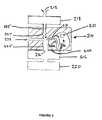
- Figure 3
- is a schematic view in section of a third example instrument.
- The example instruments provide means for determining and recording characteristics of seed in a batch of plant product.
- The first example instrument comprises a separator chamber (10) having an inlet (12) through which a batch of seed may be supplied to the separator chamber, an outlet (14) from the separator, first counter means (16), second counter means (18) and a balance (20). These are arranged one above another. The first counter means has a vibratory feeder device to separate the particulate material into individual particles, so that they pass this and the lower counter one by one.
- A fan (not shown) is provided for drawing a flow of air through the separator chamber (10) via the inlet (12) and generally from left to right as viewed in Figure 1 to separate seed passing through the separator chamber into a first fraction consisting essentially of heavier particulate material and a second fraction consisting essentially of lighter material. The instrument is so constructed and arranged that in use, particles may drop one by one past the counter (18), into the separator (10) and so that those of the first fraction may fall from the inlet (12) to the balance (20) in an at least substantially vertical, linear line of passage. The flow of air drawn through the separator chamber is such that particles are borne to a lesser or greater degree from the line of passage. Baffle means in the form of vertically extending metal plates (22, 24) is provided within the separator chamber at a position from the line of passage commensurate with restraining lighter particles from returning to the first fraction after separation. The separator chamber (10) includes a sub-chamber (26) in which the second fraction is retained. A vent (28) is provided at an upper extremity of the separator chamber through extraneous matter such as dust or plant residue may be evacuated from the separator chamber.
- Each of the counters (16 and 18) comprises an optical counting means arranged to count particles falling past it. The first counting means (16) is provided for counting the particles in the first fraction and the second counting means (18) for counting particles of the particulate material in the batch. The counting means provide the results as a digital outputs (30, 32). The balance provides means for weighing the first fraction and also provides its result as a digital output (34).
- The instrument has a bar code reader (36) which provides means for reading an identifier in the form of a bar code on the batch of particulate material supplied to the inlet. The bar code reader is arranged to supply the identifier bar code as a digital output (38).
- The instrument also comprises means (not shown) for applying the identifier to the batch of particulate material.
- The various digital outputs (30, 32, 34, 38) are fed from the instrument to a data collection point (40) at which they are integrated by use of software in a computer device. The information derived is then supplied to a computer programmed to store data in prescribed format in a database from which it may be manipulated to afford comparison of characteristics of batches of particulate material.
- The second example instrument comprises a separator chamber (110) having an inlet (112) through which a batch of plant product may be supplied to the separator chamber, an outlet (114) from the separator, first counter means (116) second counter means (118) and a balance (120). The inlet (112), outlet (114), first counter means (116) and balance (120) are arranged one above another. Fan means (not shown) as employed in the first example instrument is provided for drawing a flow of air through the separator chamber (110) to separate particulate material passing through the separator chamber into a first fraction consisting essentially of heavier particulate material and a second fraction consisting essentially of lighter material. The instrument is so constructed and arranged that in use, particles may drop from the inlet (112) via a vibratory hopper and pass one by one, into the separator chamber (110) and so that those of the first fraction may fall from the inlet (112) to the balance (120) in an at least substantially vertical, linear line of passage. The air flow in the separator chamber serves to carry particles to a lesser or greater degree from the line of passage. Baffle means in the form of vertically extending metal plates (122, 124) is provided within the separator chamber at a position from the line of passage commensurate with restraining lighter particles from returning to the first fraction after separation. The separator chamber (110) includes a sub-chamber (126) defined by the baffle (122) and a wall (125) in which the second fraction is collected. Particles of the second fraction may then pass through a conduit (127) and fall past the second counter (118) and collect in a chamber (not shown). A second sub-chamber (142) defined by the wall (125) and an interior wall portion of the separator chamber, is provided into which a third fraction of the batch may pass. A vent (128) is provided at an upper extremity of the separator chamber through which extraneous matter such as dust may be evacuated from the separator chamber.
- Each of the counters (116 and 118) comprises an optical counting means arranged to count particles falling past it. The first counting means (116) is provided for counting the particles in the first fraction and the second counting means (118) for counting particles of the second fraction. The counting means each provide results as a digital output (130, 133).
- The balance provides means for weighing the first fraction and also provides its result as a digital output (134).
- The instrument has a bar code reader (136) which provides means for reading an identifier in the form of a bar code on the batch of particulate material supplied to the inlet. The bar code reader is arranged to supply the identifier bar code as a digital output (138).
- The instrument also comprises means (not shown) for applying the identifier to the batch of particulate material.
- The various digital outputs (130, 133, 134, 138) are fed from the instrument to a data collection point (140) at which they are integrated by use of software in a computer device. The information derived is then supplied to a computer programmed to store data in prescribed format in a database from which it may be manipulated to afford comparison of characteristics of batches of seed.
- The third example instrument comprises a separator chamber (210) having an inlet (212) through which a batch of plant product may be supplied via a vibratory hopper (not shown) to the separator chamber, an outlet (214) from the separator chamber, first counter means (216), second counter means (218) and a balance (220). These are arranged one above another. A fan (221) is provided for drawing a flow of air through the separator chamber (210) via an inlet port (223) and generally from left to right as viewed in Figure 3 to separate particulate material passing through the separator chamber into a first fraction consisting essentially of heavier particulate material and a second fraction consisting essentially of lighter material. In this embodiment the particulate material is allowed to fall through a vertically disposed passageway (225) shaped (227) to disrupt the passage of particles of falling material as they reach the entry port (223) through which flow of gas may enter the separator, being drawn through the separator chamber by the fan (221). Baffles (224, 226) and an internal wall (231) of the separator chamber are curved in such a way that air drawn through the chamber follows a somewhat sinusoidal path to one side of the passageway (225) as indicated by the arrows in Figure 3.
- The instrument is so constructed and arranged that in use, particles may drop one by one past the counter (218), into the separator (210) and so that those of the first fraction may fall from the inlet (212) to the balance (220) in an at least substantially vertical line of passage. The flow of air drawn through the separator chamber is such that particles are borne to a lesser or greater degree from the line of passage. Air flowing between the baffles (224, 226) restrains lighter particles from returning to the first fraction after separation. The separator chamber (210) includes a sub-chamber (228) in which the second fraction is retained. The air drawn out of the separator chamber by the fan (221 carries extraneous matter such as dust through the fan and out of the separator chamber.
- Each of the counters (216 and 218) comprises an optical counting means arranged to count particles falling past it. The first counting means (216) is provided for counting the particles in the first fraction and the second counting means (218) for counting particles of the particulate material in the batch. The counting means provide the results as digital outputs (not shown) in the same way as in the first example instrument. The balance provides means for weighing the first fraction and also provides its result as a digital output (not shown) as in the first example instrument.
- The instrument has a bar code reader (not shown) which provides means for reading an identifier in the form of a bar code on the batch of particulate material supplied to the inlet. The bar code reader is arranged to supply the identifier bar code as a digital output.
- The instrument also comprises means (not shown) for applying the identifier to the batch of particulate material.
- As with the first example instrument the various digital outputs are fed from the instrument to a data collection point at which they are integrated by use of software in a computer device. The information derived is then supplied to a computer programmed to store data in prescribed format in a database from which it may be manipulated to afford comparison of characteristics of batches of particulate material.
- In a first process according to the invention, the first example instrument was used to determine characteristics of a batch of seed harvested from a plant. The instrument applied a unique bar code to the batch, which was read by the bar code reader (36), which in turn sent its digital output (38) to the data collection point (40) thereby identifying the batch. The batch was automatically transferred seed by seed from the inlet (12) to the separator chamber (10). Air flowing in the separator chamber caused material supplied to the separator chamber to separate into a first fraction consisting essentially of mature seeds and a second fraction consisting essentially of immature seeds and a third fraction consisting of unwanted dust and other plant materials.
- The first fraction fell onto the balance where its total weight was measured and transferred as digital output (34). The second fraction was captured in the sub-chamber (26) and the third fraction was emitted from the exhaust (28). Seed falling past the counters (18, 16) was counted by the optical devices and the result supplied as digital outputs (30, 32) to the data collection point.
- At the data collection point, the average weight of the seeds in the first fraction was determined and the data manipulated to determine the ratio of mature seeds in the batch to immature seeds in the batch. The results were sent to and recorded in a computer database in a prescribed format together with the batch identifier. The seed yield was derived from the balance output, the average seed weight was derived by taking the ratio of the seed yield to the number of mature seeds as assessed by the output of the first counter (16) and the ratio of mature seeds versus immature seeds is derived by taking the ratio of the output from the first counter (16) to the output from the second counter (18) minus the output of the first counter. Characteristics of seed yield, average seed weight and / or ratio of mature versus immature seeds in the batch were compared with corresponding characteristics of other batches of plant product assembled in the computer database.
- In a second process according to the invention, the second example instrument was used to determine characteristics of a batch of seed harvested from a plant. The instrument applied a unique bar code to the batch, which was read by the bar code reader (136), which in turn sent its digital output (138) to the data collection point (140) thereby identifying the batch. The batch was automatically transferred seed by seed from the inlet (112) to the separator chamber (110). Air flowing in the separator chamber caused material supplied to the separator chamber to separate into a first fraction consisting essentially of mature seeds, a second fraction consisting essentially of immature seeds and a third fraction consisting of unwanted dust and other plant materials.
- The first fraction fell onto the balance (120) where its total weight was measured and transferred as digital output (134). The second fraction was captured in the sub-chamber (126) and the third fraction was passed into the second sub-chamber from whence dust was exhausted via the exhaust (128). Seed falling past the counters (118, 116) was counted by the optical devices and the result supplied as digital outputs (130, 133) to the data collection point (140).
- At the data collection point, the average weight of the seeds in the first fraction was determined and the data manipulated to determine the ratio of mature seeds in the batch to immature seeds in the batch. The results were sent to and recorded in a computer database in a prescribed format together with the batch identifier. The seed yield was derived from the balance output, the average seed weight was derived by taking the ratio of the seed yield to the number of mature seeds as assessed by the output of the first counter (116) and the ratio of mature seeds versus immature seeds was derived by taking the ratio of the output from the first counter (116) to the output from the second counter (118).
- In a third process according to the invention, the third example instrument was used in a substantially similar way to the first process to separate particulate material into a first fraction consisting essentially of mature seeds and a second fraction consisting essentially of immature seeds and a third fraction consisting of extraneous materials. As in the first process, the weight of the first fraction was measured and transferred as digital output. The second fraction was captured in the sub-chamber (228) and the third fraction was exhausted through the fan (221). As in the first process, seed falling past the counters (218, 216) was counted by the optical devices and the result supplied as digital outputs to the data collection point.
- At the data collection point, the average weight of the seeds in the first fraction was determined and the data manipulated to determine the ratio of mature seeds in the batch to immature seeds in the batch. The results were sent to and recorded in a computer database in a prescribed format together with the batch identifier. The seed yield was derived from the balance output, the average seed weight was derived by taking the ratio of the seed yield to the number of mature seeds as assessed by the output of the first counter and the ratio of mature seeds versus immature seeds is derived by taking the ratio of the output from the first counter to the output from the second counter minus the output of the first counter.
- Characteristics of seed yield, average seed weight and / or ratio of mature versus immature seeds in the batch were compared with corresponding characteristics of other batches of plant product assembled in the computer database.
- One may select which of the example instruments is used in accordance with the nature of the seeds and of the impurities which depends on the plant species and the harvesting system used. In either case one may compare one or more of the characteristics of seed yield, average seed weight and / or ratio of mature versus immature seeds in a batch of plant product with corresponding characteristics of other batches of plant product, by interrogating the computer database compiled by subjecting many batches of plant product to a process according to the invention.
Claims (3)
- Apparatus for determining and recording characteristics of seed in a batch of plant product comprising a separator chamber having an inlet through which a batch of plant product may be supplied to the separator chamber, means for causing a flow of gas in the separator chamber to separate the plant product into a first fraction consisting essentially of seed having desired characteristics and a second fraction consisting essentially of seed not having the desired characteristics,
first counting means for counting the seed in the first fraction and providing the result as a digital output,
second counting means for counting seed in the batch or for counting seed in the second fraction and providing the result as a digital output, means for weighing the first fraction and providing the result as a digital output,
said apparatus being characterised in that it further comprises
means for reading an identifier on the batch of plant product supplied to the inlet, providing the identifier as a digital output, and
means for integrating said digital outputs and for transferring them to a computer programmed to store data in prescribed format in a database from which it may be manipulated to afford comparison of characteristics of batches of plant product. - A process for evaluating and recording characteristics of seed in a batch of plant product comprising the steps of identifying the batch, automatically transferring the batch to means for separating the seed to provide a first fraction consisting essentially of mature seeds and a second fraction consisting essentially of improperly matured seeds, this separation being caused by a flow of gas, to means for counting the seeds in such manner that the number of seeds in each fraction is determined and to means for weighing the first fraction of seeds, determining the average weight of the seeds in the first fraction, manipulating the results to determine the ratio of mature seeds in the batch to immature seeds in the batch and,
said process being characterised in that it also comprises the steps of
reading an identifier on the batch of plant product, providing the identifier as a digital output, and recording said results in a prescribed format in a computer database together with the batch identifier. - A process according to claim 2, wherein said computer database is interrogated for comparing one or more of the characteristics of seed yield, average seed weight and / or ratio of mature versus improperly matured seeds in a batch of plant product with corresponding characteristics of other batches of plant product.
Priority Applications (6)
| Application Number | Priority Date | Filing Date | Title |
|---|---|---|---|
| AT02080446T ATE344446T1 (en) | 2002-12-18 | 2002-12-18 | EVALUATION OF PARTICLE MATERIAL |
| DE60215836T DE60215836T2 (en) | 2002-12-18 | 2002-12-18 | Evaluation of particle material |
| EP02080446A EP1431744B1 (en) | 2002-12-18 | 2002-12-18 | Evaluation of particulate material |
| ES02080446T ES2275806T3 (en) | 2002-12-18 | 2002-12-18 | EVALUATION OF PARTICLE MATERIAL. |
| US10/740,029 US7367458B2 (en) | 2002-12-18 | 2003-12-18 | Evaluation of particulate material |
| US12/148,623 US8215491B2 (en) | 2002-12-18 | 2008-04-21 | Evaluation of particulate material |
Applications Claiming Priority (1)
| Application Number | Priority Date | Filing Date | Title |
|---|---|---|---|
| EP02080446A EP1431744B1 (en) | 2002-12-18 | 2002-12-18 | Evaluation of particulate material |
Publications (2)
| Publication Number | Publication Date |
|---|---|
| EP1431744A1 EP1431744A1 (en) | 2004-06-23 |
| EP1431744B1 true EP1431744B1 (en) | 2006-11-02 |
Family
ID=32338137
Family Applications (1)
| Application Number | Title | Priority Date | Filing Date |
|---|---|---|---|
| EP02080446A Expired - Lifetime EP1431744B1 (en) | 2002-12-18 | 2002-12-18 | Evaluation of particulate material |
Country Status (5)
| Country | Link |
|---|---|
| US (2) | US7367458B2 (en) |
| EP (1) | EP1431744B1 (en) |
| AT (1) | ATE344446T1 (en) |
| DE (1) | DE60215836T2 (en) |
| ES (1) | ES2275806T3 (en) |
Families Citing this family (6)
| Publication number | Priority date | Publication date | Assignee | Title |
|---|---|---|---|---|
| EP1431744B1 (en) * | 2002-12-18 | 2006-11-02 | CropDesign N.V. | Evaluation of particulate material |
| CN101022719B (en) | 2004-09-16 | 2010-06-09 | 克罗普迪塞恩股份有限公司 | Method and apparatus for evaluating plant roots |
| US8991098B2 (en) * | 2008-09-16 | 2015-03-31 | Basf Plant Science Gmbh | Method for improved plant breeding |
| US9025831B2 (en) * | 2009-11-10 | 2015-05-05 | Monsanto Technology Llc | Apparatus and methods for automated phenotypic screening of plant genotypes |
| CA3006474A1 (en) | 2015-12-10 | 2017-06-15 | Basf Plant Science Company Gmbh | Method and apparatus for measuring inflorescence, seed and/or seed yield phenotype |
| CN115271491A (en) * | 2022-08-04 | 2022-11-01 | 山东省林草种质资源中心(山东省药乡林场) | Method and system for sorting forest and grass germplasm resources |
Citations (1)
| Publication number | Priority date | Publication date | Assignee | Title |
|---|---|---|---|---|
| GB1378715A (en) * | 1971-02-13 | 1974-12-27 | Fahr Ag Maschf | Harvesting and/or processing machine for agricultural products |
Family Cites Families (13)
| Publication number | Priority date | Publication date | Assignee | Title |
|---|---|---|---|---|
| GB617276A (en) * | 1946-07-03 | 1949-02-03 | Ferenc Okolicsanyi | Improvements in or relating to methods and apparatus for sorting small articles such as seeds and the like |
| US4391338A (en) * | 1980-04-04 | 1983-07-05 | Harvey Patashnick | Microbalance and method for measuring the mass of matter suspended within a fluid medium |
| US4558091A (en) * | 1983-05-13 | 1985-12-10 | Grain Processing Corporation | Method for preparing aluminum and polyhydric alcohol modified liquid absorbing composition |
| US4588091A (en) * | 1983-05-27 | 1986-05-13 | Intersystems, Inc. | Method and apparatus to determine quality of particulate material |
| US4865627A (en) * | 1987-10-30 | 1989-09-12 | Shell Oil Company | Method and apparatus for separating fine particulates from a mixture of fine particulates and gas |
| US5294002A (en) * | 1990-10-03 | 1994-03-15 | Crown Iron Works Company | Air separator with spiral staves |
| DE4041994B4 (en) * | 1990-12-27 | 2006-01-05 | Cimbria Sket Gmbh | Method and device for peeling fresh rapeseed |
| US6213307B1 (en) * | 1995-11-15 | 2001-04-10 | Grana Inc. | Fluid-bed cleaner and grades sorter for particle form materials |
| US5949001A (en) * | 1998-02-17 | 1999-09-07 | Willeke; Klaus | Method for aerodynamic particle size analysis |
| US6502450B1 (en) * | 1999-05-10 | 2003-01-07 | Rupprecht & Patashnik Company, Inc. | Single detector differential particulate mass monitor with intrinsic correction for volatilization losses |
| AU2001297736A1 (en) * | 2000-11-13 | 2002-10-08 | University Of Southern California | High-quality continuous particulate matter monitor |
| US6706989B2 (en) * | 2001-02-02 | 2004-03-16 | Pioneer Hi-Bred International, Inc. | Automated high-throughput seed sample processing system and method |
| EP1431744B1 (en) * | 2002-12-18 | 2006-11-02 | CropDesign N.V. | Evaluation of particulate material |
-
2002
- 2002-12-18 EP EP02080446A patent/EP1431744B1/en not_active Expired - Lifetime
- 2002-12-18 DE DE60215836T patent/DE60215836T2/en not_active Expired - Lifetime
- 2002-12-18 AT AT02080446T patent/ATE344446T1/en not_active IP Right Cessation
- 2002-12-18 ES ES02080446T patent/ES2275806T3/en not_active Expired - Lifetime
-
2003
- 2003-12-18 US US10/740,029 patent/US7367458B2/en not_active Expired - Fee Related
-
2008
- 2008-04-21 US US12/148,623 patent/US8215491B2/en not_active Expired - Fee Related
Patent Citations (1)
| Publication number | Priority date | Publication date | Assignee | Title |
|---|---|---|---|---|
| GB1378715A (en) * | 1971-02-13 | 1974-12-27 | Fahr Ag Maschf | Harvesting and/or processing machine for agricultural products |
Also Published As
| Publication number | Publication date |
|---|---|
| ATE344446T1 (en) | 2006-11-15 |
| US20040172157A1 (en) | 2004-09-02 |
| ES2275806T3 (en) | 2007-06-16 |
| US8215491B2 (en) | 2012-07-10 |
| DE60215836T2 (en) | 2007-08-30 |
| DE60215836D1 (en) | 2006-12-14 |
| EP1431744A1 (en) | 2004-06-23 |
| US7367458B2 (en) | 2008-05-06 |
| US20080197057A1 (en) | 2008-08-21 |
Similar Documents
| Publication | Publication Date | Title |
|---|---|---|
| US8215491B2 (en) | Evaluation of particulate material | |
| Jahnke et al. | Pheno seeder-a robot system for automated handling and phenotyping of individual seeds | |
| RU2350067C2 (en) | Technique and device for retrieval of data on grain combine harvester screening mass | |
| CN101905215B (en) | Digitalized paddy rice seed testing machine | |
| US11650189B2 (en) | Grain separation automation and processing equipment and possible materials of identification, classification and quantification of the same; application of process and use of equipment | |
| US20040118754A1 (en) | Automated high-throughput seed sample handling system and method | |
| CN110583217A (en) | Grain harvester cleaning loss rate detection device and detection method | |
| US10712325B2 (en) | Method and apparatus for measuring inflorescence, seed and/or seed yield phenotype | |
| CN113575014A (en) | Feeding structure, feeding device and seed testing machine | |
| Dowell et al. | An automated near‐infrared system for selecting individual kernels based on specific quality characteristics | |
| Adewumi et al. | Preliminary investigation on the distribution and spread pattern of cowpea in a cross flow grain separator | |
| CA3209370A1 (en) | System and method for measuring grain particle granulometry and grain particle granulometry measurement system calibration method | |
| Thomasson et al. | Cotton mass flow measurement: experiments with two optical devices | |
| Masoumi et al. | Effect of awn on aerodynamic properties of paddy grains (Oryza Sativa L. | |
| JP7535243B2 (en) | Grain inspection device and cultivation management system using said device | |
| CN215774357U (en) | Small-size rice and wheat combined test platform is used in scientific research | |
| Taylor et al. | Sorting capability and grain recovery of deoxynivalenol contaminated wheat is affected by calibration and vitreous kernel settings from near-infrared transmittance technology | |
| JP7428966B2 (en) | color sorter | |
| Churchill et al. | Separation of mixed lots of tall fescue and ryegrass seed using machine vision | |
| JP7432151B2 (en) | Self-testing device and self-testing method | |
| CN119804895B (en) | An integrated automatic inspection system for grain quality | |
| Berlage et al. | The application of new technologies to seed conditioning | |
| CN113519278B (en) | A small rice and wheat comprehensive test bench for scientific research and its measurement method | |
| CN119470220B (en) | Lost grain identification system and method based on energy differentiation method and regression model | |
| JPS5847376Y2 (en) | Grain particle feeding device |
Legal Events
| Date | Code | Title | Description |
|---|---|---|---|
| PUAI | Public reference made under article 153(3) epc to a published international application that has entered the european phase |
Free format text: ORIGINAL CODE: 0009012 |
|
| AK | Designated contracting states |
Kind code of ref document: A1 Designated state(s): AT BE BG CH CY CZ DE DK EE ES FI FR GB GR IE IT LI LU MC NL PT SE SI SK TR |
|
| AX | Request for extension of the european patent |
Extension state: AL LT LV MK RO |
|
| 17P | Request for examination filed |
Effective date: 20040707 |
|
| 17Q | First examination report despatched |
Effective date: 20041011 |
|
| AKX | Designation fees paid |
Designated state(s): AT BE BG CH CY CZ DE DK EE ES FI FR GB GR IE IT LI LU MC NL PT SE SI SK TR |
|
| GRAP | Despatch of communication of intention to grant a patent |
Free format text: ORIGINAL CODE: EPIDOSNIGR1 |
|
| GRAS | Grant fee paid |
Free format text: ORIGINAL CODE: EPIDOSNIGR3 |
|
| 17Q | First examination report despatched |
Effective date: 20041011 |
|
| GRAA | (expected) grant |
Free format text: ORIGINAL CODE: 0009210 |
|
| AK | Designated contracting states |
Kind code of ref document: B1 Designated state(s): AT BE BG CH CY CZ DE DK EE ES FI FR GB GR IE IT LI LU MC NL PT SE SI SK TR |
|
| PG25 | Lapsed in a contracting state [announced via postgrant information from national office to epo] |
Ref country code: SI Free format text: LAPSE BECAUSE OF FAILURE TO SUBMIT A TRANSLATION OF THE DESCRIPTION OR TO PAY THE FEE WITHIN THE PRESCRIBED TIME-LIMIT Effective date: 20061102 Ref country code: CZ Free format text: LAPSE BECAUSE OF FAILURE TO SUBMIT A TRANSLATION OF THE DESCRIPTION OR TO PAY THE FEE WITHIN THE PRESCRIBED TIME-LIMIT Effective date: 20061102 Ref country code: FI Free format text: LAPSE BECAUSE OF FAILURE TO SUBMIT A TRANSLATION OF THE DESCRIPTION OR TO PAY THE FEE WITHIN THE PRESCRIBED TIME-LIMIT Effective date: 20061102 Ref country code: AT Free format text: LAPSE BECAUSE OF FAILURE TO SUBMIT A TRANSLATION OF THE DESCRIPTION OR TO PAY THE FEE WITHIN THE PRESCRIBED TIME-LIMIT Effective date: 20061102 Ref country code: SK Free format text: LAPSE BECAUSE OF FAILURE TO SUBMIT A TRANSLATION OF THE DESCRIPTION OR TO PAY THE FEE WITHIN THE PRESCRIBED TIME-LIMIT Effective date: 20061102 |
|
| REG | Reference to a national code |
Ref country code: GB Ref legal event code: FG4D |
|
| REG | Reference to a national code |
Ref country code: IE Ref legal event code: FG4D |
|
| REG | Reference to a national code |
Ref country code: CH Ref legal event code: EP |
|
| REF | Corresponds to: |
Ref document number: 60215836 Country of ref document: DE Date of ref document: 20061214 Kind code of ref document: P |
|
| PG25 | Lapsed in a contracting state [announced via postgrant information from national office to epo] |
Ref country code: MC Free format text: LAPSE BECAUSE OF NON-PAYMENT OF DUE FEES Effective date: 20061231 |
|
| PG25 | Lapsed in a contracting state [announced via postgrant information from national office to epo] |
Ref country code: BG Free format text: LAPSE BECAUSE OF FAILURE TO SUBMIT A TRANSLATION OF THE DESCRIPTION OR TO PAY THE FEE WITHIN THE PRESCRIBED TIME-LIMIT Effective date: 20070202 Ref country code: DK Free format text: LAPSE BECAUSE OF FAILURE TO SUBMIT A TRANSLATION OF THE DESCRIPTION OR TO PAY THE FEE WITHIN THE PRESCRIBED TIME-LIMIT Effective date: 20070202 Ref country code: SE Free format text: LAPSE BECAUSE OF FAILURE TO SUBMIT A TRANSLATION OF THE DESCRIPTION OR TO PAY THE FEE WITHIN THE PRESCRIBED TIME-LIMIT Effective date: 20070202 |
|
| REG | Reference to a national code |
Ref country code: CH Ref legal event code: NV Representative=s name: SCHMAUDER & PARTNER AG PATENTANWALTSBUERO |
|
| PG25 | Lapsed in a contracting state [announced via postgrant information from national office to epo] |
Ref country code: PT Free format text: LAPSE BECAUSE OF FAILURE TO SUBMIT A TRANSLATION OF THE DESCRIPTION OR TO PAY THE FEE WITHIN THE PRESCRIBED TIME-LIMIT Effective date: 20070402 |
|
| ET | Fr: translation filed | ||
| REG | Reference to a national code |
Ref country code: ES Ref legal event code: FG2A Ref document number: 2275806 Country of ref document: ES Kind code of ref document: T3 |
|
| PLBE | No opposition filed within time limit |
Free format text: ORIGINAL CODE: 0009261 |
|
| STAA | Information on the status of an ep patent application or granted ep patent |
Free format text: STATUS: NO OPPOSITION FILED WITHIN TIME LIMIT |
|
| 26N | No opposition filed |
Effective date: 20070803 |
|
| PG25 | Lapsed in a contracting state [announced via postgrant information from national office to epo] |
Ref country code: GR Free format text: LAPSE BECAUSE OF FAILURE TO SUBMIT A TRANSLATION OF THE DESCRIPTION OR TO PAY THE FEE WITHIN THE PRESCRIBED TIME-LIMIT Effective date: 20070203 |
|
| PG25 | Lapsed in a contracting state [announced via postgrant information from national office to epo] |
Ref country code: EE Free format text: LAPSE BECAUSE OF FAILURE TO SUBMIT A TRANSLATION OF THE DESCRIPTION OR TO PAY THE FEE WITHIN THE PRESCRIBED TIME-LIMIT Effective date: 20061102 |
|
| PG25 | Lapsed in a contracting state [announced via postgrant information from national office to epo] |
Ref country code: LU Free format text: LAPSE BECAUSE OF NON-PAYMENT OF DUE FEES Effective date: 20061218 Ref country code: TR Free format text: LAPSE BECAUSE OF FAILURE TO SUBMIT A TRANSLATION OF THE DESCRIPTION OR TO PAY THE FEE WITHIN THE PRESCRIBED TIME-LIMIT Effective date: 20061102 |
|
| PG25 | Lapsed in a contracting state [announced via postgrant information from national office to epo] |
Ref country code: CY Free format text: LAPSE BECAUSE OF FAILURE TO SUBMIT A TRANSLATION OF THE DESCRIPTION OR TO PAY THE FEE WITHIN THE PRESCRIBED TIME-LIMIT Effective date: 20061102 |
|
| REG | Reference to a national code |
Ref country code: CH Ref legal event code: PCAR Free format text: SCHMAUDER & PARTNER AG PATENT- UND MARKENANWAELTE VSP;ZWAENGIWEG 7;8038 ZUERICH (CH) |
|
| PG25 | Lapsed in a contracting state [announced via postgrant information from national office to epo] |
Ref country code: FR Free format text: LAPSE BECAUSE OF NON-PAYMENT OF DUE FEES Effective date: 20091231 |
|
| REG | Reference to a national code |
Ref country code: FR Ref legal event code: PLFP Year of fee payment: 14 |
|
| PGFP | Annual fee paid to national office [announced via postgrant information from national office to epo] |
Ref country code: GB Payment date: 20151230 Year of fee payment: 14 Ref country code: CH Payment date: 20151223 Year of fee payment: 14 Ref country code: IE Payment date: 20151223 Year of fee payment: 14 |
|
| PGFP | Annual fee paid to national office [announced via postgrant information from national office to epo] |
Ref country code: FR Payment date: 20151228 Year of fee payment: 14 Ref country code: NL Payment date: 20151223 Year of fee payment: 14 |
|
| PGFP | Annual fee paid to national office [announced via postgrant information from national office to epo] |
Ref country code: ES Payment date: 20160121 Year of fee payment: 14 Ref country code: IT Payment date: 20151221 Year of fee payment: 14 Ref country code: DE Payment date: 20160302 Year of fee payment: 14 |
|
| PGFP | Annual fee paid to national office [announced via postgrant information from national office to epo] |
Ref country code: BE Payment date: 20151224 Year of fee payment: 14 |
|
| PG25 | Lapsed in a contracting state [announced via postgrant information from national office to epo] |
Ref country code: BE Free format text: LAPSE BECAUSE OF NON-PAYMENT OF DUE FEES Effective date: 20161231 |
|
| REG | Reference to a national code |
Ref country code: DE Ref legal event code: R119 Ref document number: 60215836 Country of ref document: DE |
|
| REG | Reference to a national code |
Ref country code: CH Ref legal event code: PL |
|
| REG | Reference to a national code |
Ref country code: NL Ref legal event code: MM Effective date: 20170101 |
|
| GBPC | Gb: european patent ceased through non-payment of renewal fee |
Effective date: 20161218 |
|
| PG25 | Lapsed in a contracting state [announced via postgrant information from national office to epo] |
Ref country code: NL Free format text: LAPSE BECAUSE OF NON-PAYMENT OF DUE FEES Effective date: 20170101 |
|
| REG | Reference to a national code |
Ref country code: FR Ref legal event code: ST Effective date: 20170831 |
|
| REG | Reference to a national code |
Ref country code: IE Ref legal event code: MM4A |
|
| PG25 | Lapsed in a contracting state [announced via postgrant information from national office to epo] |
Ref country code: CH Free format text: LAPSE BECAUSE OF NON-PAYMENT OF DUE FEES Effective date: 20161231 Ref country code: FR Free format text: LAPSE BECAUSE OF NON-PAYMENT OF DUE FEES Effective date: 20170102 Ref country code: LI Free format text: LAPSE BECAUSE OF NON-PAYMENT OF DUE FEES Effective date: 20161231 Ref country code: IT Free format text: LAPSE BECAUSE OF NON-PAYMENT OF DUE FEES Effective date: 20161218 |
|
| PG25 | Lapsed in a contracting state [announced via postgrant information from national office to epo] |
Ref country code: GB Free format text: LAPSE BECAUSE OF NON-PAYMENT OF DUE FEES Effective date: 20161218 Ref country code: IE Free format text: LAPSE BECAUSE OF NON-PAYMENT OF DUE FEES Effective date: 20161218 Ref country code: DE Free format text: LAPSE BECAUSE OF NON-PAYMENT OF DUE FEES Effective date: 20170701 |
|
| REG | Reference to a national code |
Ref country code: BE Ref legal event code: MM Effective date: 20161231 |
|
| PG25 | Lapsed in a contracting state [announced via postgrant information from national office to epo] |
Ref country code: ES Free format text: LAPSE BECAUSE OF NON-PAYMENT OF DUE FEES Effective date: 20161219 |
|
| REG | Reference to a national code |
Ref country code: ES Ref legal event code: FD2A Effective date: 20181116 |