EP1431626A1 - Shift control device for automatic transmission - Google Patents
Shift control device for automatic transmission Download PDFInfo
- Publication number
- EP1431626A1 EP1431626A1 EP02768113A EP02768113A EP1431626A1 EP 1431626 A1 EP1431626 A1 EP 1431626A1 EP 02768113 A EP02768113 A EP 02768113A EP 02768113 A EP02768113 A EP 02768113A EP 1431626 A1 EP1431626 A1 EP 1431626A1
- Authority
- EP
- European Patent Office
- Prior art keywords
- hydraulic pressure
- pressure
- friction element
- solenoid
- valve
- Prior art date
- Legal status (The legal status is an assumption and is not a legal conclusion. Google has not performed a legal analysis and makes no representation as to the accuracy of the status listed.)
- Granted
Links
Images





Classifications
-
- F—MECHANICAL ENGINEERING; LIGHTING; HEATING; WEAPONS; BLASTING
- F16—ENGINEERING ELEMENTS AND UNITS; GENERAL MEASURES FOR PRODUCING AND MAINTAINING EFFECTIVE FUNCTIONING OF MACHINES OR INSTALLATIONS; THERMAL INSULATION IN GENERAL
- F16H—GEARING
- F16H61/00—Control functions within control units of change-speed- or reversing-gearings for conveying rotary motion ; Control of exclusively fluid gearing, friction gearing, gearings with endless flexible members or other particular types of gearing
- F16H61/12—Detecting malfunction or potential malfunction, e.g. fail safe ; Circumventing or fixing failures
-
- F—MECHANICAL ENGINEERING; LIGHTING; HEATING; WEAPONS; BLASTING
- F16—ENGINEERING ELEMENTS AND UNITS; GENERAL MEASURES FOR PRODUCING AND MAINTAINING EFFECTIVE FUNCTIONING OF MACHINES OR INSTALLATIONS; THERMAL INSULATION IN GENERAL
- F16H—GEARING
- F16H59/00—Control inputs to control units of change-speed- or reversing-gearings for conveying rotary motion
- F16H59/68—Inputs being a function of gearing status
- F16H2059/6807—Status of gear-change operation, e.g. clutch fully engaged
-
- F—MECHANICAL ENGINEERING; LIGHTING; HEATING; WEAPONS; BLASTING
- F16—ENGINEERING ELEMENTS AND UNITS; GENERAL MEASURES FOR PRODUCING AND MAINTAINING EFFECTIVE FUNCTIONING OF MACHINES OR INSTALLATIONS; THERMAL INSULATION IN GENERAL
- F16H—GEARING
- F16H59/00—Control inputs to control units of change-speed- or reversing-gearings for conveying rotary motion
- F16H59/68—Inputs being a function of gearing status
- F16H2059/683—Sensing pressure in control systems or in fluid-controlled devices, e.g. by pressure sensors
-
- F—MECHANICAL ENGINEERING; LIGHTING; HEATING; WEAPONS; BLASTING
- F16—ENGINEERING ELEMENTS AND UNITS; GENERAL MEASURES FOR PRODUCING AND MAINTAINING EFFECTIVE FUNCTIONING OF MACHINES OR INSTALLATIONS; THERMAL INSULATION IN GENERAL
- F16H—GEARING
- F16H61/00—Control functions within control units of change-speed- or reversing-gearings for conveying rotary motion ; Control of exclusively fluid gearing, friction gearing, gearings with endless flexible members or other particular types of gearing
- F16H61/02—Control functions within control units of change-speed- or reversing-gearings for conveying rotary motion ; Control of exclusively fluid gearing, friction gearing, gearings with endless flexible members or other particular types of gearing characterised by the signals used
- F16H61/0202—Control functions within control units of change-speed- or reversing-gearings for conveying rotary motion ; Control of exclusively fluid gearing, friction gearing, gearings with endless flexible members or other particular types of gearing characterised by the signals used the signals being electric
- F16H61/0204—Control functions within control units of change-speed- or reversing-gearings for conveying rotary motion ; Control of exclusively fluid gearing, friction gearing, gearings with endless flexible members or other particular types of gearing characterised by the signals used the signals being electric for gearshift control, e.g. control functions for performing shifting or generation of shift signal
- F16H61/0206—Layout of electro-hydraulic control circuits, e.g. arrangement of valves
- F16H2061/0209—Layout of electro-hydraulic control circuits, e.g. arrangement of valves with independent solenoid valves modulating the pressure individually for each clutch or brake
-
- F—MECHANICAL ENGINEERING; LIGHTING; HEATING; WEAPONS; BLASTING
- F16—ENGINEERING ELEMENTS AND UNITS; GENERAL MEASURES FOR PRODUCING AND MAINTAINING EFFECTIVE FUNCTIONING OF MACHINES OR INSTALLATIONS; THERMAL INSULATION IN GENERAL
- F16H—GEARING
- F16H61/00—Control functions within control units of change-speed- or reversing-gearings for conveying rotary motion ; Control of exclusively fluid gearing, friction gearing, gearings with endless flexible members or other particular types of gearing
- F16H61/12—Detecting malfunction or potential malfunction, e.g. fail safe ; Circumventing or fixing failures
- F16H2061/1208—Detecting malfunction or potential malfunction, e.g. fail safe ; Circumventing or fixing failures with diagnostic check cycles; Monitoring of failures
-
- F—MECHANICAL ENGINEERING; LIGHTING; HEATING; WEAPONS; BLASTING
- F16—ENGINEERING ELEMENTS AND UNITS; GENERAL MEASURES FOR PRODUCING AND MAINTAINING EFFECTIVE FUNCTIONING OF MACHINES OR INSTALLATIONS; THERMAL INSULATION IN GENERAL
- F16H—GEARING
- F16H61/00—Control functions within control units of change-speed- or reversing-gearings for conveying rotary motion ; Control of exclusively fluid gearing, friction gearing, gearings with endless flexible members or other particular types of gearing
- F16H61/12—Detecting malfunction or potential malfunction, e.g. fail safe ; Circumventing or fixing failures
- F16H2061/1224—Adapting to failures or work around with other constraints, e.g. circumvention by avoiding use of failed parts
-
- F—MECHANICAL ENGINEERING; LIGHTING; HEATING; WEAPONS; BLASTING
- F16—ENGINEERING ELEMENTS AND UNITS; GENERAL MEASURES FOR PRODUCING AND MAINTAINING EFFECTIVE FUNCTIONING OF MACHINES OR INSTALLATIONS; THERMAL INSULATION IN GENERAL
- F16H—GEARING
- F16H61/00—Control functions within control units of change-speed- or reversing-gearings for conveying rotary motion ; Control of exclusively fluid gearing, friction gearing, gearings with endless flexible members or other particular types of gearing
- F16H61/12—Detecting malfunction or potential malfunction, e.g. fail safe ; Circumventing or fixing failures
- F16H2061/1232—Bringing the control into a predefined state, e.g. giving priority to particular actuators or gear ratios
- F16H2061/1236—Bringing the control into a predefined state, e.g. giving priority to particular actuators or gear ratios using fail priority valves
-
- F—MECHANICAL ENGINEERING; LIGHTING; HEATING; WEAPONS; BLASTING
- F16—ENGINEERING ELEMENTS AND UNITS; GENERAL MEASURES FOR PRODUCING AND MAINTAINING EFFECTIVE FUNCTIONING OF MACHINES OR INSTALLATIONS; THERMAL INSULATION IN GENERAL
- F16H—GEARING
- F16H61/00—Control functions within control units of change-speed- or reversing-gearings for conveying rotary motion ; Control of exclusively fluid gearing, friction gearing, gearings with endless flexible members or other particular types of gearing
- F16H61/12—Detecting malfunction or potential malfunction, e.g. fail safe ; Circumventing or fixing failures
- F16H2061/1244—Keeping the current state
-
- F—MECHANICAL ENGINEERING; LIGHTING; HEATING; WEAPONS; BLASTING
- F16—ENGINEERING ELEMENTS AND UNITS; GENERAL MEASURES FOR PRODUCING AND MAINTAINING EFFECTIVE FUNCTIONING OF MACHINES OR INSTALLATIONS; THERMAL INSULATION IN GENERAL
- F16H—GEARING
- F16H61/00—Control functions within control units of change-speed- or reversing-gearings for conveying rotary motion ; Control of exclusively fluid gearing, friction gearing, gearings with endless flexible members or other particular types of gearing
- F16H61/12—Detecting malfunction or potential malfunction, e.g. fail safe ; Circumventing or fixing failures
- F16H2061/1256—Detecting malfunction or potential malfunction, e.g. fail safe ; Circumventing or fixing failures characterised by the parts or units where malfunctioning was assumed or detected
- F16H2061/126—Detecting malfunction or potential malfunction, e.g. fail safe ; Circumventing or fixing failures characterised by the parts or units where malfunctioning was assumed or detected the failing part is the controller
- F16H2061/1268—Electric parts of the controller, e.g. a defect solenoid, wiring or microprocessor
-
- F—MECHANICAL ENGINEERING; LIGHTING; HEATING; WEAPONS; BLASTING
- F16—ENGINEERING ELEMENTS AND UNITS; GENERAL MEASURES FOR PRODUCING AND MAINTAINING EFFECTIVE FUNCTIONING OF MACHINES OR INSTALLATIONS; THERMAL INSULATION IN GENERAL
- F16H—GEARING
- F16H2200/00—Transmissions for multiple ratios
- F16H2200/20—Transmissions using gears with orbital motion
- F16H2200/2097—Transmissions using gears with orbital motion comprising an orbital gear set member permanently connected to the housing, e.g. a sun wheel permanently connected to the housing
-
- F—MECHANICAL ENGINEERING; LIGHTING; HEATING; WEAPONS; BLASTING
- F16—ENGINEERING ELEMENTS AND UNITS; GENERAL MEASURES FOR PRODUCING AND MAINTAINING EFFECTIVE FUNCTIONING OF MACHINES OR INSTALLATIONS; THERMAL INSULATION IN GENERAL
- F16H—GEARING
- F16H3/00—Toothed gearings for conveying rotary motion with variable gear ratio or for reversing rotary motion
- F16H3/44—Toothed gearings for conveying rotary motion with variable gear ratio or for reversing rotary motion using gears having orbital motion
- F16H3/62—Gearings having three or more central gears
- F16H3/66—Gearings having three or more central gears composed of a number of gear trains without drive passing from one train to another
- F16H3/663—Gearings having three or more central gears composed of a number of gear trains without drive passing from one train to another with conveying rotary motion between axially spaced orbital gears, e.g. a stepped orbital gear or Ravigneaux
-
- F—MECHANICAL ENGINEERING; LIGHTING; HEATING; WEAPONS; BLASTING
- F16—ENGINEERING ELEMENTS AND UNITS; GENERAL MEASURES FOR PRODUCING AND MAINTAINING EFFECTIVE FUNCTIONING OF MACHINES OR INSTALLATIONS; THERMAL INSULATION IN GENERAL
- F16H—GEARING
- F16H61/00—Control functions within control units of change-speed- or reversing-gearings for conveying rotary motion ; Control of exclusively fluid gearing, friction gearing, gearings with endless flexible members or other particular types of gearing
- F16H61/02—Control functions within control units of change-speed- or reversing-gearings for conveying rotary motion ; Control of exclusively fluid gearing, friction gearing, gearings with endless flexible members or other particular types of gearing characterised by the signals used
- F16H61/0202—Control functions within control units of change-speed- or reversing-gearings for conveying rotary motion ; Control of exclusively fluid gearing, friction gearing, gearings with endless flexible members or other particular types of gearing characterised by the signals used the signals being electric
- F16H61/0204—Control functions within control units of change-speed- or reversing-gearings for conveying rotary motion ; Control of exclusively fluid gearing, friction gearing, gearings with endless flexible members or other particular types of gearing characterised by the signals used the signals being electric for gearshift control, e.g. control functions for performing shifting or generation of shift signal
- F16H61/0206—Layout of electro-hydraulic control circuits, e.g. arrangement of valves
-
- F—MECHANICAL ENGINEERING; LIGHTING; HEATING; WEAPONS; BLASTING
- F16—ENGINEERING ELEMENTS AND UNITS; GENERAL MEASURES FOR PRODUCING AND MAINTAINING EFFECTIVE FUNCTIONING OF MACHINES OR INSTALLATIONS; THERMAL INSULATION IN GENERAL
- F16H—GEARING
- F16H61/00—Control functions within control units of change-speed- or reversing-gearings for conveying rotary motion ; Control of exclusively fluid gearing, friction gearing, gearings with endless flexible members or other particular types of gearing
- F16H61/68—Control functions within control units of change-speed- or reversing-gearings for conveying rotary motion ; Control of exclusively fluid gearing, friction gearing, gearings with endless flexible members or other particular types of gearing specially adapted for stepped gearings
- F16H61/684—Control functions within control units of change-speed- or reversing-gearings for conveying rotary motion ; Control of exclusively fluid gearing, friction gearing, gearings with endless flexible members or other particular types of gearing specially adapted for stepped gearings without interruption of drive
- F16H61/686—Control functions within control units of change-speed- or reversing-gearings for conveying rotary motion ; Control of exclusively fluid gearing, friction gearing, gearings with endless flexible members or other particular types of gearing specially adapted for stepped gearings without interruption of drive with orbital gears
-
- Y—GENERAL TAGGING OF NEW TECHNOLOGICAL DEVELOPMENTS; GENERAL TAGGING OF CROSS-SECTIONAL TECHNOLOGIES SPANNING OVER SEVERAL SECTIONS OF THE IPC; TECHNICAL SUBJECTS COVERED BY FORMER USPC CROSS-REFERENCE ART COLLECTIONS [XRACs] AND DIGESTS
- Y10—TECHNICAL SUBJECTS COVERED BY FORMER USPC
- Y10S—TECHNICAL SUBJECTS COVERED BY FORMER USPC CROSS-REFERENCE ART COLLECTIONS [XRACs] AND DIGESTS
- Y10S477/00—Interrelated power delivery controls, including engine control
- Y10S477/906—Means detecting or ameliorating the effects of malfunction or potential malfunction
Definitions
- the present invention relates to a shift control system of an automatic transmission having a hydraulic pressure circuit which is constituted of solenoid hydraulic pressure control valves for controlling individually an engagement pressure and a disengagement pressure to a plurality of friction elements related to shift of the automatic transmission.
- Described in the above publication includes a technology for changing gear from first speed 1ST, second speed 2ND and third speed 3RD to third speed 3RD and from fourth speed 4TH, fifth 5TH and sixth speed 6TH to sixth speed 6TH in a case of an electric failure caused to a traveling vehicle.
- the third speed 3RD capable of causing a great driving force sufficient for start signifies that the driving force can be secured for the vehicle to travel.
- the shift control system of the automatic transmission changes the gear from the first speed 1 ST, second speed 2ND and third speed 3RD to the third speed 3RD while from the fourth speed 4TH, fifth 5TH and sixth speed 6TH to the sixth speed 6TH in the electric failure by means of a fail safe valve 77, a fail safe valve 78, a fail safe valve 79, a fail safe valve 80 and a fail safe valve 81 each of which operates with pressure of one of respective friction elements as an operation signal pressure.
- the shift control system of the automatic transmission according to the above conventional technology may cause an insensible- failure which may be attributable, for example, to the fail safe valve 77 sticking to a spring's extension side (hereinafter, the insensible failure is referred to as a sleeping failure), thus causing an interlock.
- a duty solenoid SLC1 cutting a C-1 hydraulic pressure contributes to trouble-free (sleeping failure), when the fail safe valve 77 sticks (in failure) to the spring's extension side at an ordinary fifth speed 5TH.
- the following failures may cause the interlock attributable to simultaneous engagements of a plurality of friction elements: 1. the electric failure, 2. cutting of the duty solenoid SLC1, or 3. the duty solenoid SLC1 sticking to the hydraulic pressure output side.
- Substantially the like reduction is supposed to hold true to the fail safe valve 78, the fail safe valve 79, the fail safe valve 80 and the fail safe valve 81 in the sleeping failure.
- Disposed between the duty solenoids and the friction elements include the fail safe valve 77, the fail safe valve 78, the fail safe valve 79, the fail safe valve 80 and the fail safe valve 81 and the like each of which operates with the pressure of one of the respective friction elements as the operation signal pressure.
- changing the gear may output three or more of the hydraulic pressures substantially simultaneously.
- controlling at high hydraulic pressure may cause malfunction to the fail safe valve 77, the fail safe valve 78, the fail safe valve 79, the fail safe valve 80 and the fail safe valve 81 and the like, thus restricting hydraulic pressure control range and deteriorating shift controllability.
- the fifth speed 5TH and sixth speed 6TH to the sixth speed 6TH may use three long (overall length) fail safe valves (namely, the fail safe valve 77, the fail safe valve 78, and the fail safe valve 81) having two shifts, and two fail safe valves (namely, the fail safe valve 79, and the fail safe valve 80), thus complicating the layout and increasing a control valve unit in size.
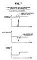
- gear change from the fourth speed 4TH, the fifth speed 5TH and the sixth speed 6TH to the sixth speed 6TH in the electric failure involves gears of two or more (fourth speed 4TH to sixth speed 6TH), thus causing an excessive shock (down spike and up spike).
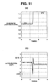
- Fig. 11 shows a resultant diagram of an up shift simulation of changing the gear from the fourth speed 4TH to the sixth speed 6TH in the case of fuse cut (electric failure) caused to the vehicle traveling at 230 km/h with fourth speed 4TH.
- the up shift simulation from the fourth speed 4TH to the sixth speed 6TH causes deceleration of -0.25 G and up spike acceleration of +0.21 G, thus causing acceleration-deceleration range of 0.46 G (> 0.4 G).
- the present invention has been invented. It is an object of the present invention to provided a shift control system of an automatic transmission that can securely prevent an interlock by eliminating a sleeping failure, and that can secure a high shift controllability which is not, in a period of shift, restricted in terms of hydraulic pressure control range of each of friction elements.
- a hydraulic pressure circuit has a constitution provided with solenoid hydraulic pressure control valves for controlling individually an engagement pressure and a disengagement pressure to a plurality of friction elements related to a shift of the automatic transmission.
- the shift control system of the automatic transmission includes a shift controlling means for achieving a plurality of forward gears by outputting the following commands when the shift is requested; an engagement pressure control command to the solenoid hydraulic pressure control valves of the friction elements which is disengaged at a gear before the shift and is engaged at a gear after the shift, and a disengagement pressure control command to the solenoid hydraulic pressure control valves of the friction elements which is engaged at the gear before the shift and is disengaged at the gear after the shift.
- the shift control system of the automatic transmission comprises:
- the electric failure determining means inputs the hydraulic pressure sensing signal from the hydraulic pressure sensing means for sensing whether or not the pressure of the friction elements is present.
- the electric failure determining means makes the comparison between the supposedly-engaged friction element of the friction elements and the actually-engaged friction element of the friction elements which is sensed by the hydraulic pressure sensing signal to be actually engaged.
- the electric failure determining means determines that the electric system is in failure.
- the electric failure interlock escaping means sticks the gear of the automatic transmission to the given gear.
- the aspect of the present invention has divided functions, namely, the electric failure sensing function is carried out by the electric failure determining means with the sensing function based on the hydraulic pressure sensing signal from the hydraulic pressure sensing means, while the electric failure interlock escaping function is carried out by the electric failure interlock escaping means for sticking the gear to its given position with the escaping function based on an electric failure determination result.
- use of the hydraulic pressure sensing means for sensing the electric failure can eliminate the insensible sleeping failure which is attributable to the sticking fail safe valve, thus securely preventing the interlock.
- eliminating the need for providing between the solenoid hydraulic pressure control valves and the friction elements the fail safe valve which operates with the pressure of each of the friction elements as operation signal pressure can secure high shift controllability which is not, in a period of shift, restricted in terms of hydraulic pressure control range of each of the friction elements.
- the all-power source OFF control determining means determines whether or not the all power sources can be turned off.
- the electric failure interlock escaping means carries out the control for sticking the gear to the escape gear which is provided for each of the failure modes.
- the electric failure interlock escaping means carries out the control for sticking the gear to its given position with the all power sources turned off.
- the routine turns off the all power sources and controls the gear to stick to the fifth speed 5TH among the six forward gears, thus bringing about the gear change from the fourth speed 4TH to the fifth speed 5TH, from the fifth speed 5TH to the fifth speed 5TH, and from the sixth speed 6TH to the fifth speed 5TH in the electric failure which may be caused to the high gear (fourth speed 4TH, fifth speed 5TH, and sixth speed 6TH) traveling vehicle.
- the above gears can prevent any excessive shock which may be caused by the gear change, for example, from the fourth speed 4TH to the sixth speed 6TH.
- the electric failure interlock escaping means before turning off the ignition key and with the all power sources turned off may engage the second friction element and engage, via the fail safe valve, the third friction element, while the electric failure interlock escaping means for restart after turning off the ignition key may engage the second friction element and engage the first friction element by switching the fail safe valve for cutting the engagement pressure of the third friction element.
- the routine sticks the gear to the fifth speed 5TH by engaging the second friction element and the third friction element, while for restart after turning off the ignition key, the routine sticks the gear to the third speed 3RD by engaging the first friction element and the second friction element.
- the routine can prevent the excessive shock which may be caused in the electric failure to the high gear traveling vehicle and can compatibly secure restartability after the electric failure.
- the solenoid valve outputting the solenoid pressure may so switch the valve position as to allow the first fail safe valve to cut the hydraulic pressure passage of the first friction element while connect the hydraulic pressure passage to the third friction element. Substantially simultaneously with this, the thus outputted hydraulic pressure applied from the direction same as the direction of the solenoid valve may keep the thus switched valve position. Thereafter, whether or not the solenoid pressure is outputted from the solenoid valve, the first fail safe valve can keep outputting the hydraulic pressure (self hold pressure).
- the second fail safe valve may select the position for supplying the engagement pressure to the third friction element.
- the second fail safe valve may select the position for supplying the engagement pressure to the first friction element.
- the solenoid valve, the first fail safe valve and the second fail safe valve constitute the system that can select two gears in the electric failure.
- the thus constituted system can facilitate valve layout and make control valve unit smaller, as compared with the conventional technology for selecting the two gears in the electric failure.
- the solenoid valve is a solenoid valve for causing the operation signal pressure of the switch valve disposed on the engagement hydraulic pressure passage to the first friction element having the first engagement piston chamber and the second engagement piston chamber which are engaged in accordance with engagement capacity request.
- the solenoid valve constitutes the fail safe solenoid valve. The above common solenoid valve helps reduce the number of component parts and cost, as compared with the solenoid valves equipped for carrying out the above respective functions.
- the solenoid valve 30 (for bringing about the solenoid pressure to the first fail safe valve) outputting even once the solenoid pressure may, whether or not the solenoid pressure is outputted thereafter, allow the first fail safe valve 31 to keep outputting the self hold pressure.
- Described at first is a constitution.
- Fig. 1 is a skeleton diagram showing a gear train of an automatic transmission having six forward gears and one reverse gear, where a shift control system according to the mode for carrying out is applied to the automatic transmission.
- the automatic transmission uses, as the gear train, a combination of one simple planet gear set G1 and one Ravigneaux gear set G2.
- the simple planet gear set G1 is constituted of a first sun gear S1, a first carrier C1, and a first ring gear R1.
- the Ravigneaux gear set G2 is constituted of a second sun gear S2, a second carrier C2, a third sun gear S3, a third carrier C3, and a third ring gear R3.
- an input shaft IN to which an engine driving force is inputted by way of an engine (not shown) and a torque converter (not shown).
- the input shaft IN directly connects to the first ring gear R1 by way of a first member M1, and also connects to the third carrier C3 by way of a second member M2 and a high clutch H/C.
- the first carrier C1 connects to the third sun gear S3 by way of a third member M3, a low clutch LOW/C and a fifth member M5, and also connects to the second sun gear S2 by way of the third member M3, a 3-5 reverse clutch 3-5 R/C, and a sixth member M6.
- the sixth member M6 is fixed to a transmission case TC by way of a 2-6 brake 2-6/B.
- the first sun gear S1 is fixed to the transmission case TC by way of a fourth member M4.
- the second carrier C2 is fixed to the transmission case TC by way of a seventh member M7, a low & reverse brake L & R/B, and a low one-way clutch LOW/OWC which latter two members are arranged in parallel.
- the third ring gear R3 connects to an output gear OUT by way of an eighth member M8.
- Fig. 2 shows an operation list showing each friction element of the shift control.
- a void circle signifies an engaged state
- an empty block signifies a disengaged state
- X in the void circle signifies the engaged state in an engine brake
- a hatched circle signifies a mechanical operation in an engine driving period.
- a first speed 1ST is achieved through engagement of the low clutch LOW/C and the low & reverse brake L & R/B.
- rotation of the input shaft IN reduced through the first member M1 and the simple plant gear set G1 is inputted to the third sun gear S3 by way of the third member M3, the low clutch LOW/C, and the fifth member M5.
- Engaging the low one-way clutch LOW/OWC may fix the second carrier C2 to the transmission case TC.
- the third ring gear R3 is reduced in rotation while receiving a reaction from the thus fixed second carrier C2, so that reduced rotation at the maximum reduction ratio is outputted from the output gear OUT by way of the eighth member M8.
- the low & reverse brake L & R/B receives a reaction in place of the low one-way clutch LOW/OWC which is idling.
- a second speed 2ND is achieved through engagement of the low clutch LOW/C and the 2-6 brake 2-6/B.
- rotation of the input shaft IN reduced through the first member M1 and the simple planet gear set G1 is inputted to the third sun gear S3 through the third member M3, the low clutch LOW/C and the fifth member M5.
- Engaging the 2-6-brake 2-6/B may fix the second sun gear S2 to the transmission case TC.
- the third ring gear R3 is reduced in rotation while receiving a reaction from the thus fixed second sun gear S2, so that reduced rotation at a reduction ratio smaller than that of the first speed 1ST is outputted from the output gear OUT through the eighth member M8.
- Third speed 3RD is achieved through engagement of the low lutch LOW/C and the 3-5 reverse clutch 3-5 R/C.
- rotation of the input shaft IN reduced through the first member M1 and the simple plant gear set G1 is inputted to the third sun gear S3 through the third member M3, the low clutch LOW/C, and the fifth member M5, and also to the second sun gear S2 through the third member M3, the 3-5 reverse clutch 3-5 R/C, and the sixth member M6, achieving direct coupling f the Ravigneaux-type composite planet gear set G2.
- the third ring gear R3 is rotated in the same rotation as those of the second sun gear S2 and the third sun gear S3, so that reduced rotation at a reduction ratio smaller than that of the second speed 2ND is outputted from the output gear OUT through the eighth member M8.
- Fourth speed 4TH is achieved through engagement of the low clutch LOW/C and the high clutch H/C.
- rotation of the input shaft IN reduced through the first member M1 and the simple planet gear set G1 is inputted to the third sun gear S3 through the third member M3, the low clutch LOW/C, and the fifth member M5.
- rotation of the input shaft IN without being reduced is inputted to the third carrier C3 through the second member M2 and the high clutch H/C.
- the third ring gear R3 is rotated at substantially the middle rotation rate between the two input-rotation rates, so that rotation slightly reduced relative to input rotations is outputted from the output gear OUT through the eighth member M8.
- Fifth speed 5TH is achieved through engagement of the 3-5 reverse clutch 3-5 R/C and the high clutch H/C.
- rotation of the input shaft IN reduced through the first member M1 and the simple plant gear set G1 is inputted to the second sun gear S2 through the third member M3, the 3-5 reverse clutch 3-5 R/C, and the sixth member M6.
- rotation of the input shaft IN without being reduced is inputted to the third carrier C3 through the second member M2 and the high clutch H/C.
- the third ring gear R3 is rotated in such a manner as to be restricted by the two rotations, so that rotation slightly increased relative to input rotations is outputted from the output gear OUT through the eighth member M8.
- Sixth speed 6TH is achieved through engagement of the high clutch H/C and the 2-6 brake 2-6/B.
- rotation of the input shaft IN without being reduced namely, with the input rotation kept
- Engaging the 2-6 brake 2-6/B may fix the second sun gear S2 to the transmission case TC.
- the third ring gear R3 is increased in rotation while receiving a reaction from the thus fixed second sun gear S2, so that rotation further increased relative to fifth speed 5TH is outputted from the output gear OUT through the eighth member M8.
- Reverse speed REV is achieved through engagement of the 3-5 reverse clutch 3-5 R/C and the low & reverse brake L & R/B.
- rotation of the input shaft IN reduced through the first member M1 and the simple planet gear set G1 is inputted to the second sun gear S2 through the third member M3, the 3-5 reverse clutch 3-5 R/C, and the sixth member M6.
- Engaging the low & reverse brake L & R/B may fix the second carrier C2 to the transmission case TC.
- the third ring gear R3 is rotated in the reverse direction while receiving a reaction from the thus fixed second carrier C2, so that reduced reverse rotation is outputted from the output gear OUT through the eighth member M8.
- a hydraulic pressure circuit and an electronic shift control system for achieving the above shift control are described in terms of constitution.
- a first engagement piston chamber 1a of the low clutch LOW/C first friction element
- a second engagement piston chamber 1b of the high clutch H/C first friction element
- an engagement piston chamber 2 of the high clutch H/C third friction element
- an engagement piston chamber 3 of the 2-6 brake 2-6/B an engagement piston chamber 4 of the 3-5 reverse clutch 3-5 R/C (second friction element)
- an engagement piston chamber 5 of the low & reverse brake L & R/B the low clutch LOW/C has the above two engagement piston chambers, namely, the first engagement piston chamber 1a and the second engagement piston chamber 1b to be engageable in accordance with an engagement capacity request.
- a first solenoid hydraulic pressure control valve 6 for controlling the engagement pressure to the low clutch LOW/C
- a second solenoid hydraulic pressure control valve 7 for controlling the engagement pressure to the high clutch H/C
- a third solenoid hydraulic pressure control valve 8 for controlling the engagement pressure to the 2-6 brake 2-6/B
- a fourth solenoid hydraulic pressure control valve 9 for controlling the engagement pressure to the 3-5 reverse clutch 3-5 R/C
- a fifth solenoid hydraulic pressure control valve 10 for controlling the engagement pressure to the low & reverse brake L & R/B.
- the first solenoid hydraulic pressure control valve 6 comprises a first duty solenoid 6a for producing the shift control pressure by a solenoid force with the pilot pressure as source pressure, and a first pressure regulator valve 6b for regulating the low clutch pressure with the D range pressure as source pressure and the shift control pressure and feedback pressure as operation signal pressure.
- the first duty solenoid 6a is controlled in accordance with the duty ratio in such a manner as to bring the low clutch pressure to zero when the solenoid is turned off, and increase the low clutch pressure with an increase in the ON duty ratio when the solenoid is turned on.
- the second solenoid hydraulic pressure control valve 7 comprises a second duty solenoid 7a for producing the shift control pressure by a solenoid force with the pilot pressure as source pressure, and a second pressure regulator valve 7b for regulating the high clutch pressure with the D range pressure as source pressure and the shift control pressure and feedback pressure as operation signal pressure.
- the second duty solenoid 7a is controlled in such a manner as to bring the high clutch pressure to zero when the solenoid is turned on (100% ON duty ratio), increase the high clutch pressure with a decrease in the ON duty ratio, and bring the high clutch pressure to its maximum when the solenoid is turned off.
- the third solenoid hydraulic pressure control valve 8 comprises a third duty solenoid 8a for producing the shift control pressure by a solenoid force with the pilot pressure as source pressure, and a third pressure regulator valve 8b for regulating the 2-6 brake pressure with the D range pressure as source pressure and the shift control pressure and feedback pressure as operation signal pressure.
- the third duty solenoid 8a is controlled in such a manner as to bring the 2-3 brake pressure to zero when the solenoid is turned off, and increase the 2-3 brake pressure with an increase in the ON duty ratio when the solenoid is turned on.
- the fourth solenoid hydraulic pressure control valve 9 comprises a fourth duty solenoid 9a for producing the shift control pressure by a solenoid force with the pilot pressure as source pressure, and a fourth pressure regulator valve 9b for regulating the 3-5 reverse clutch pressure with the line pressure as source pressure and the shift control pressure, R range pressure and feedback pressure as operation signal pressure.
- the fourth duty solenoid 9a is controlled in such a manner as to bring the 3-5 reverse clutch pressure to zero when the solenoid is turned on (100% ON duty ratio), increase the reverse clutch pressure with a decrease in the ON duty ration, and bring the reverse clutch pressure to its maximum when the solenoid is turned off.
- the fifth solenoid hydraulic pressure control valve 10 comprises a fifth duty solenoid 10a for producing the shift control pressure by a solenoid force with the pilot pressure as source pressure, and a fifth pressure regulator valve 10b for regulating the low & reverse brake pressure with the D range pressure or the R range pressure as source pressure and the shift control pressure and feedback pressure as operation signal pressure.
- the fifth duty solenoid 10a is controlled in such a manner as to bring the low & reverse brake pressure to zero when the solenoid is turned off, and increase the low & reverse brake pressure with an increase in the ON duty ratio when the solenoid is turned on.
- a first hydraulic pressure switch 11 hydraulic pressure sensing means
- a second hydraulic pressure switch 12 hydraulic pressure sensing means
- a third hydraulic pressure switch 13 hydraulic pressure sensing means
- a fourth hydraulic pressure switch 14 hydraulic pressure sensing means
- a fifth hydraulic pressure switch 15 hydraulic pressure sensing means
- a manual valve 16 pilot valve 17, a line pressure passage 19, a pilot pressure passage 20, a D range hydraulic pressure passage 21, an R range hydraulic pressure passage 22, a D & R range hydraulic pressure passage 23, a first low clutch hydraulic pressure passage 24a, a second low clutch hydraulic pressure passage 24b, a high clutch hydraulic pressure passage 25; a 2-6 brake hydraulic pressure passage 26, a 3-5 reverse clutch hydraulic pressure passage 27, and a low & reverse brake hydraulic pressure passage 28.
- the first hydraulic pressure switch 11, the second hydraulic pressure switch 12, the third hydraulic pressure switch 13, the fourth hydraulic pressure switch 14 and the fifth hydraulic pressure switch 15 are arranged respectively in the first low clutch hydraulic pressure passage 24a, the high clutch hydraulic pressure passage 25, the 2-6 brake hydraulic pressure passage 26, the 3-5 reverse clutch hydraulic pressure passage 27, and the low & reverse brake hydraulic pressure passage 28, so as to sense the presence of the engagement pressure in accordance with switch signals which are turned on when the engagement pressure is present and turned off when the engagement pressure is not present.
- a solenoid valve 30 a first fail safe valve 31, a second fail safe valve 32, a switch valve 33, a solenoid hydraulic pressure passage 34, and a self hold hydraulic pressure passage 35.
- the solenoid valve 30 is an ON/OFF switch valve which uses the solenoid force for operating the valve with the pilot pressure as source pressure. When the solenoid is turned on, the solenoid valve 30 outputs the solenoid pressure attributable to the pilot pressure, while when the solenoid is turned off, the solenoid valve 30 drains the solenoid pressure attributable to the pilot pressure.
- the first fail safe valve 31 is a spool valve which is fitted with a spring for applying a biasing force in a direction opposite to a direction of operation signal pressure with the line pressure as source pressure, where the operation signal pressure is defined as the solenoid pressure (from the solenoid valve 30) and the feedback output pressure (line pressure). With the solenoid pressure outputted from the solenoid valve 30, the feedback output pressure can keep the output of the line pressure.
- the second fail safe valve 32 is a spool valve for switching two positions.
- the second fail safe valve 32 is fitted with a spring for applying a biasing force in a direction same as a direction of a self hold pressure (line pressure) from the first fail safe valve 32 with the self hold pressure and the line pressure as operation signal pressure.
- line pressure self hold pressure
- the second fail safe valve 32 selects a side for supplying the D range pressure to the high clutch H/C, while when the self hold pressure is not caused, the second fail safe valve 32 selects a side for supplying the D range pressure to the low clutch LOW/C.
- the switch valve 33 is disposed on the second low clutch hydraulic pressure passage 24b.
- the switch valve 33 is a spool valve operating with the solenoid pressure (from the solenoid valve 30) as operation signal pressure.
- the solenoid pressure is not outputted from the solenoid valve 30
- the switch valve 33 supplies the hydraulic pressure to both the first engagement piston chamber 1a and the second engagement piston chamber 1b.
- the switch valve 33 drains the hydraulic pressure of the second engagement piston chamber 1b, and supplies the hydraulic pressure to the first engagement piston chamber 1a.
- an automatic transmission control unit 40 (shift controlling means) and a shift lever 50.
- the shift lever 50 has a P range for locking a transmission output shaft in stoppage of the vehicle, an R range for achieving the reverse gear, an N range for achieving a neutral state which shows a state in which forward movement and reverse movement are possible without outputting the input torque of the vacant engine, a D range for achieving each of the forward gears, and an engine brake range for controlling in such a manner as to engage the low & reverse brake L & R/B at the first shift.
- the shift lever 50 connects to the manual valve 16. The driver operating the shift lever 50 can shift the position of the manual valve 16, thus achieving the target shift.
- a vehicle speed sensor 41 a throttle sensor 42 for sensing throttle opening, an engine speed sensor 43 for sensing engine speed, a turbine speed sensor 44 for sensing turbine speed, an inhibitor switch 45 for sensing the position (range) of the shift lever 50, and an oil temperature sensor 46 for sensing oil temperature in the transmission.
- the vehicle speed sensor 41, the throttle sensor 42, the engine speed sensor 43, the turbine sped sensor 44, the inhibitor switch 45 and the oil temperature sensor 46 constitute the electronic shift control system in combination with the automatic transmission control unit 40.
- the automatic transmission control unit 40 inputs switch signals from the first hydraulic pressure switch 11, the second hydraulic pressure switch 12, the third hydraulic pressure switch 13, the fourth hydraulic pressure switch 14 and the fifth hydraulic pressure switch 15 and signals from the vehicle speed sensor 41, the throttle sensor 42, the engine speed sensor 43, the turbine speed sensor 44, the inhibitor switch 45 and the oil temperature sensor 46, so as to carry out computing in accordance with the above input information, a preprogrammed shift control regulation; a preprogrammed fail safe control regulation and the like.
- the automatic transmission control unit 40 outputs solenoid drive signals to the first duty solenoid 6a, the second duty solenoid 7a, the third duty solenoid 8a, the fourth duty solenoid 9a, the fifth duty solenoid 10a and the solenoid valve 30.
- Fig. 4 is a flow chart showing a fail safe control process carried out with the automatic transmission control unit 40 and a fail safe operation involved with the fail safe control process. Hereinafter, the description is made on each step.
- step S7 to step S17 correspond to the electric failure interlock escaping means as set forth in claims.
- the routine takes sequentially the step S1, the step S2, the step S3, the step S4, and the step S5 in the flow chart in Fig. 4. Then, the routine moves from the step S5 back to the step S2, followed by the repeated sequential movement of taking the step S3, the step S4 and the step S5.
- the routine for example at D range travel of the vehicle, compares the operation point (determined from the vehicular speed sensed with the vehicle speed sensor 41 and from the throttle opening sensed with the throttle sensor 42) with a predetermined shift schedule.
- the operation point crossing a shift line of the shift schedule carries out an ordinary shift control, namely, the gear of the operation point before the crossing is shifted (up or down) to the gear of the operation point after the crossing.
- the routine takes sequentially the step S1, the step S2, the step S3, the step S4, the step S5, the step S6 and the step S7 in the flow chart in Fig. 4.
- the routine carries out the fail safe shift control for sticking the gear to the escape gear.
- the routine carries out the fail safe shift control for sticking the gear to the escape gear, which control can be achieved by the operable solenoid and the like.
- the routine sequentially takes the step S1, the step S2, the step S3, the step S4, the step S5, the step S6, the step S8, the step S9, the step S10 and the step S11 in the flow chart in Fig. 4.
- the routine sticks the gear to the fifth speed 5TH by differentiating in polarity the second duty solenoid 7a and the fourth duty solenoid 9a from the other solenoids.
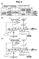
- the solenoid valve 30 outputting even once the solenoid pressure before the electric failure is caused may switch the spool of the first fail safe valve 31 to the spring's shrink side, as is seen in Fig. 5(b). Substantially simultaneously with this, the output pressure from the first fail safe valve 31 may act in the direction same as the direction of the solenoid pressure, thus causing the self hold pressure for holding the spool in the present position (switched position). Whether or not the solenoid pressure is outputted from the solenoid valve 30, the thus caused self hold pressure may stick the first fail safe valve 31 on the spring's shrink side, thus holding the output pressure.
- the second fail safe valve 32 sticking to the spring's shrink side with the output pressure applied from the first fail safe valve 31 allows the spool to be held in the position for supplying the D range pressure to the second solenoid hydraulic pressure control valve 7 of the high clutch H/C.
- the second duty solenoid 7a and the fourth duty solenoid 9a are so polarized as to output the high clutch pressure and the 3-5 reverse clutch pressure respectively when the second duty solenoid 7a and the fourth duty solenoid 9a are electrically turned off.
- the other duty solenoids do not output the engagement pressure when the other duty solenoids are electrically turned off. With this, turning off the all power sources may engage the high clutch H/C and the 3-5 reverse clutch 3-5 R/C, thus sticking the gear to the fifth speed 5TH (see Fig. 2).
- the routine sequentially takes the step S12, the step S13, the step S14, the step S15, the step S16, and the step S17 in the flow chart in Fig. 4.
- the routine sticks the gear to the third speed 3RD.
- Turning off the ignition key may stop an oil pump, thus turning off the operation of the hydraulic pressure, and further thus cutting the source pressure of the first fail safe valve 31 and releasing the self hold pressure.
- the spool of the first fail safe valve 31 makes the stroke to the spring's extension side.
- turning on the ignition key for restart may recover the hydraulic pressure operation.
- the above cut output pressure of the first fail safe valve 31 may stick the spool of the second fail safe valve 32 to the spring's shrink side by the hydraulic pressure applied to the spring's opposite side, thus inputting the D range pressure directly to the low clutch LOW/C and cutting the source pressure of the high clutch H/C.
- restarting the routine after turning off the ignition key may engage the low clutch LOW/C (attributable to the turned on hydraulic pressure [from the oil pump] after the turned off hydraulic pressure [from the oil pump]) and engage the 3-5 reverse clutch 3-5 R/C (attributable to all power sources turned off), thus sticking the gear to the third speed 3RD (see Fig. 2).
- Fig. 5(a) summarizes the fail safe operations before and after the ignition key is turned off in the case of the electric failure capable of turning off the all power sources.
- the routine takes sequentially the step S4, the step 8, the step 9, the step 10, the step 11, the step 12, the step 13, the step 14, the step 15, the step 16, and the step 17.
- the above described applicability is to the automatic transmission that has the six forward gears and the one reverse gear.
- the applicability is also to an automatic transmission that has four forward gears, five forward gears, seven forward gears and the like, provided that such automatic transmission has a hydraulic pressure circuit constitution which has solenoid hydraulic pressure control valves for controlling individually engagement pressures to a plurality of friction elements related to shift of the automatic transmission.
- the engagement pressure of the friction element is sensed with the hydraulic switch.
- a hydraulic pressure sensor capable of sensing a state (engagement and disengagement) is, however, replaceable.
- the solenoid valve 30 sending the operation signal pressure to the first fail safe valve and the second safe valve is of a selectable valve type for turning on and off.
- the present invention is, however, not limited to the above type.
Landscapes
- Engineering & Computer Science (AREA)
- General Engineering & Computer Science (AREA)
- Mechanical Engineering (AREA)
- Control Of Transmission Device (AREA)
Abstract
Description
an engagement pressure control command to the solenoid hydraulic pressure control valves of the friction elements which is disengaged at a gear before the shift and is engaged at a gear after the shift, and
a disengagement pressure control command to the solenoid hydraulic pressure control valves of the friction elements which is engaged at the gear before the shift and is disengaged at the gear after the shift.
for a restart after the ignition key is turned off, the fail safe valve cutting the engagement pressure of the third friction element while supplying the engagement pressure to the first friction element.
Claims (6)
- A shift control system of an automatic transmission, a hydraulic pressure circuit having a constitution provided with solenoid hydraulic pressure control valves for controlling individually an engagement pressure and a disengagement pressure to a plurality of friction elements related to a shift of the automatic transmission, the shift control system of the automatic transmission including a shift controlling means for achieving a plurality of forward gears by outputting the following commands when the shift is requested;
an engagement pressure control command to the solenoid hydraulic pressure control valves of the friction elements which is disengaged at a gear before the shift and is engaged at a gear after the shift, and
a disengagement pressure control command to the solenoid hydraulic pressure control valves of the friction elements which is engaged at the gear before the shift and is disengaged at the gear after the shift,
the shift control system of the automatic transmission comprising:1) a hydraulic pressure sensing means for sensing whether or not a pressure of the friction elements is present, the hydraulic pressure sensing means being disposed on the plurality of the friction elements or each of engagement-disengagement hydraulic pressure passages;2) an electric failure determining means for determining that an electric system is in failure through:a comparison between the following friction elements, when a hydraulic pressure sensing signal is inputted from the hydraulic pressure sensing means and when any of the forward gears is held:a supposedly-engaged friction element of the friction elements which is supposed to be engaged at the any of the forward gears, andan actually-engaged friction element of the friction elements which is sensed by the hydraulic pressure sensing signal to be actually engaged, anda determination that the supposedly-engaged friction element is not in accordance with the actually-engaged friction element; and3) an electric failure interlock escaping means for sticking the gear of the automatic transmission to a given gear when the electric failure determining means determines that the electric failure is caused. - The shift control system of the automatic transmission as claimed in claim 1, wherein
the shift control system further comprises an all-power source OFF control determining means for determining, based on an engagement-disengagement state of the friction elements, a capability of turning off all power source, when the electric failure determining means determines that the electric failure is caused, and
when the all power source is determined to be incapable of being turned off, the electric failure interlock escaping means is so controlled as to stick the gear of the automatic transmission to an escape gear provided for each failure mode; while when the all power source is determined to be capable of being turned off, the electric failure interlock escaping means is so controlled, with the all power source turned off, as to stick the gear of the automatic transmission to the given gear. - The shift control system of the automatic transmission as claimed in claim 2, wherein
the shift controlling means is a means for achieving six forward gears, and
the electric failure interlock escaping means is a means for turning off the all power source and sticking the gear to a fifth speed when:the electric failure determining means determines that the electric failure is caused, andthe all-power source OFF control determining means determines that the all power source is capable of being turned off. - The shift control system of the automatic transmission as claimed in claim 3, wherein
the shift controlling means is a means for achieving a third speed by engaging a first friction element with a second friction element as a common friction element and for achieving a fifth speed by engaging a third friction element with the second friction element as the common friction element,
the solenoid hydraulic pressure control valves include a fourth solenoid hydraulic pressure control valve for the second friction element and a second solenoid hydraulic pressure control valve for the third friction element, the fourth solenoid hydraulic pressure control valve and the second solenoid hydraulic pressure control valve supplying the engagement pressure, respectively, to the second friction element and the third friction element in an electrically turned off state, and
a fail safe valve is disposed on an engagement hydraulic pressure passage of the first friction element and on an engagement hydraulic pressure passage of the third friction element,
when the all power source is turned off and before an ignition key is turned off, the fail safe valve supplying the engagement pressure to the third friction element while cutting the engagement pressure of the first friction element, and
for a restart after the ignition key is turned off, the fail safe valve cutting the engagement pressure of the third friction element while supplying the engagement pressure to the first friction element. - The shift control system of the automatic transmission as claimed in claim 4, wherein
the fail safe valve includes:a solenoid valve,a first fail safe valve outputting a hydraulic pressure with a solenoid pressure outputted from the solenoid valve as an operation signal pressure, the first fail safe valve having a self hold function for holding a self hydraulic pressure output by a self output hydraulic pressure with the outputted hydraulic pressure operating in a direction same as a direction of the solenoid pressure, anda second fail safe valve selecting, with the hydraulic pressure outputted from the first fail safe valve as an operation signal pressure, a side for supplying the engagement pressure to the third friction element when the hydraulic pressure of the first fail safe valve is outputted, while the second fail safe valve selecting, with the hydraulic pressure outputted from the first fail safe valve as the operation signal pressure, a side for supplying the engagement pressure to the first friction element when the hydraulic pressure of the first fail safe valve is not outputted. - The shift control system of the automatic transmission as claimed in claim 5, wherein
the first friction element has a first engagement piston chamber and a second engagement piston chamber which are engageable in accordance with an engagement capacity request,
a switch valve is disposed on the engagement hydraulic pressure passage to the first friction element, the switch valve making a first switching operation of supplying the hydraulic pressure to both of the first engagement piston chamber and the second engagement piston chamber and a second switching operation of supplying the hydraulic pressure to the first engagement piston chamber, and
the solenoid valve acts as a one common solenoid valve for causing an operation signal pressure of the switch valve and for constituting the fail safe valve.
Applications Claiming Priority (3)
| Application Number | Priority Date | Filing Date | Title |
|---|---|---|---|
| JP2001302947 | 2001-09-28 | ||
| JP2001302947 | 2001-09-28 | ||
| PCT/JP2002/010059 WO2003029700A1 (en) | 2001-09-28 | 2002-09-27 | Shift control device for automatic transmission |
Publications (3)
| Publication Number | Publication Date |
|---|---|
| EP1431626A1 true EP1431626A1 (en) | 2004-06-23 |
| EP1431626A4 EP1431626A4 (en) | 2007-10-03 |
| EP1431626B1 EP1431626B1 (en) | 2009-11-11 |
Family
ID=19123103
Family Applications (1)
| Application Number | Title | Priority Date | Filing Date |
|---|---|---|---|
| EP02768113A Expired - Lifetime EP1431626B1 (en) | 2001-09-28 | 2002-09-27 | Shift control device for automatic transmission |
Country Status (5)
| Country | Link |
|---|---|
| US (1) | US6966862B2 (en) |
| EP (1) | EP1431626B1 (en) |
| JP (1) | JP3965386B2 (en) |
| DE (1) | DE60234363D1 (en) |
| WO (1) | WO2003029700A1 (en) |
Cited By (11)
| Publication number | Priority date | Publication date | Assignee | Title |
|---|---|---|---|---|
| WO2006097209A1 (en) * | 2005-03-18 | 2006-09-21 | Zf Friedrichshafen Ag | Gear control device |
| WO2006097210A1 (en) * | 2005-03-18 | 2006-09-21 | Zf Friedrichshafen Ag | Electrohydraulic gear control device |
| DE102005024691B4 (en) * | 2004-05-31 | 2008-05-29 | Aisin AW Co., Ltd., Anjo | Hydraulic control device for an automatic vehicle transmission |
| CN1920345B (en) * | 2005-08-26 | 2010-08-18 | 加特可株式会社 | Fail detecting apparatus for automatic transmission |
| EP1729038A3 (en) * | 2005-05-31 | 2010-10-20 | JATCO Ltd | Automatic transmission control method and system having fail-safe function |
| EP1818573A3 (en) * | 2006-01-26 | 2010-12-15 | JATCO Ltd | Automatic transmission control system |
| EP1750041A3 (en) * | 2005-08-01 | 2011-03-02 | Toyota Jidosha Kabushiki Kaisha | Control apparatus for vehicular automatic transmission |
| CN102808940A (en) * | 2012-08-12 | 2012-12-05 | 哈尔滨东安汽车发动机制造有限公司 | Controlling method for preventing interlocking between gears of six-speed automatic transmission |
| US8434381B2 (en) | 2009-08-28 | 2013-05-07 | GM Global Technology Operations LLC | Transmission for a motor vehicle |
| DE112006002889B4 (en) | 2005-12-28 | 2018-07-19 | Aisin Aw Co., Ltd. | Hydraulic control device for an automatic transmission |
| DE102020214121A1 (en) | 2020-11-10 | 2022-05-12 | Zf Friedrichshafen Ag | Emergency operation strategy for a motor vehicle drive train comprising an automatic transmission that can be driven by a plurality of drive machines |
Families Citing this family (17)
| Publication number | Priority date | Publication date | Assignee | Title |
|---|---|---|---|---|
| CN100366956C (en) * | 2003-12-10 | 2008-02-06 | 株式会社电装 | Automatic shift control system with shift lever position sensor |
| US7198587B2 (en) * | 2003-12-16 | 2007-04-03 | General Motors Corporation | Transmission with selectable braking one-way clutch |
| JP4211646B2 (en) * | 2004-03-19 | 2009-01-21 | トヨタ自動車株式会社 | Hydraulic control device for automatic transmission |
| JP4453468B2 (en) * | 2004-07-16 | 2010-04-21 | 日産自動車株式会社 | Preceding vehicle following travel control device |
| JP2006046542A (en) * | 2004-08-05 | 2006-02-16 | Toyota Motor Corp | Hydraulic control device for automatic transmission for vehicle |
| JP4353148B2 (en) * | 2005-07-13 | 2009-10-28 | トヨタ自動車株式会社 | Control device for automatic transmission |
| KR100868207B1 (en) * | 2006-07-19 | 2008-11-11 | 현대자동차주식회사 | Hydraulic control device for 7-speed automatic transmission |
| US8086380B2 (en) * | 2006-11-17 | 2011-12-27 | GM Global Technology Operations LLC | Variable bleed solenoid recovery system |
| US7648440B2 (en) * | 2007-01-24 | 2010-01-19 | Gm Global Technology Operations, Inc. | Method and apparatus to control operation of an electro-mechanical transmission |
| US7670254B2 (en) * | 2007-01-24 | 2010-03-02 | Gm Global Technology Operations, Inc. | Method and apparatus to monitor devices of a hydraulic circuit of an electro-mechanical transmission |
| US8113988B2 (en) * | 2008-04-04 | 2012-02-14 | GM Global Technology Operations LLC | Hydraulic control module for vehicle transmission and diagnostic detection method for the same |
| JP5126056B2 (en) * | 2008-12-26 | 2013-01-23 | アイシン・エィ・ダブリュ株式会社 | Control device for automatic transmission |
| US8221288B2 (en) * | 2009-06-05 | 2012-07-17 | Allison Transmission, Inc. | Electro-hydraulic control system diagnostics |
| WO2017043340A1 (en) * | 2015-09-11 | 2017-03-16 | ジヤトコ株式会社 | Automatic transmission and fault determination method for automatic transmissions |
| CA3107303C (en) | 2018-12-20 | 2023-02-14 | Halliburton Energy Services, Inc. | Wellsite pumping systems and methods of operation |
| EA039848B1 (en) * | 2020-09-18 | 2022-03-18 | Открытое Акционерное Общество "Минский Завод Колёсных Тягачей" | Electrohydraulic gearshift control system of a six-speed hydromechanic gearbox |
| CN114838122B (en) * | 2022-03-29 | 2023-10-27 | 中国人民解放军陆军装甲兵学院 | A fault detection system and method for in-the-loop transmission shift hydraulic system |
Family Cites Families (18)
| Publication number | Priority date | Publication date | Assignee | Title |
|---|---|---|---|---|
| JPS4838575B1 (en) * | 1970-11-21 | 1973-11-19 | ||
| AU612674B2 (en) * | 1987-06-24 | 1991-07-18 | Kabushiki Kaisha Komatsu Seisakusho | Transmission controller |
| JPS6435155A (en) | 1987-07-30 | 1989-02-06 | Komatsu Mfg Co Ltd | Safety device for transmission |
| AU628508B2 (en) * | 1990-03-20 | 1992-09-17 | Kabushiki Kaisha Komatsu Seisakusho | Abnormality detection device for speed change system |
| US5609067A (en) * | 1994-10-14 | 1997-03-11 | Caterpillar Inc. | Transmission control fault detection |
| JP3374168B2 (en) | 1994-12-01 | 2003-02-04 | ジヤトコ株式会社 | Transmission control device for automatic transmission |
| JP3519161B2 (en) | 1995-03-22 | 2004-04-12 | ジヤトコ株式会社 | Automotive control device |
| JP2876108B2 (en) * | 1995-05-12 | 1999-03-31 | アイシン・エィ・ダブリュ株式会社 | Control device for automatic transmission |
| JP3637631B2 (en) * | 1995-05-12 | 2005-04-13 | マツダ株式会社 | Automatic transmission failure determination device and failure determination method |
| US6125321A (en) * | 1996-06-07 | 2000-09-26 | Toyota Jidosha Kabushiki Kaisha | Motor vehicle drive system controller and automatic drive controller |
| JP3687341B2 (en) * | 1998-03-30 | 2005-08-24 | マツダ株式会社 | Control device for automatic transmission |
| JP3354873B2 (en) | 1998-07-28 | 2002-12-09 | ダイハツ工業株式会社 | Hydraulic control device for automatic transmission for vehicles |
| JP4253899B2 (en) | 1999-02-24 | 2009-04-15 | アイシン・エィ・ダブリュ株式会社 | Hydraulic control device for automatic transmission |
| US6149548A (en) * | 1999-04-01 | 2000-11-21 | Daimlerchrysler Corporation | Element overlap control for an automatic transmission |
| JP3736604B2 (en) * | 1999-08-20 | 2006-01-18 | ジヤトコ株式会社 | Automatic transmission failure speed change control device |
| JP3652561B2 (en) | 1999-09-21 | 2005-05-25 | ジヤトコ株式会社 | Control device for automatic transmission |
| JP3695257B2 (en) * | 1999-10-19 | 2005-09-14 | 日産自動車株式会社 | Fail-safe system for direct acting valve type automatic transmission |
| JP4270530B2 (en) * | 2000-01-31 | 2009-06-03 | 本田技研工業株式会社 | Control device for automatic transmission for vehicle |
-
2002
- 2002-09-27 JP JP2003532879A patent/JP3965386B2/en not_active Expired - Fee Related
- 2002-09-27 WO PCT/JP2002/010059 patent/WO2003029700A1/en not_active Ceased
- 2002-09-27 DE DE60234363T patent/DE60234363D1/en not_active Expired - Lifetime
- 2002-09-27 US US10/490,161 patent/US6966862B2/en not_active Expired - Lifetime
- 2002-09-27 EP EP02768113A patent/EP1431626B1/en not_active Expired - Lifetime
Cited By (15)
| Publication number | Priority date | Publication date | Assignee | Title |
|---|---|---|---|---|
| DE102005024691B4 (en) * | 2004-05-31 | 2008-05-29 | Aisin AW Co., Ltd., Anjo | Hydraulic control device for an automatic vehicle transmission |
| WO2006097210A1 (en) * | 2005-03-18 | 2006-09-21 | Zf Friedrichshafen Ag | Electrohydraulic gear control device |
| US7794349B2 (en) | 2005-03-18 | 2010-09-14 | Zf Friedrichshafen Ag | Gear control device |
| WO2006097209A1 (en) * | 2005-03-18 | 2006-09-21 | Zf Friedrichshafen Ag | Gear control device |
| EP1729038A3 (en) * | 2005-05-31 | 2010-10-20 | JATCO Ltd | Automatic transmission control method and system having fail-safe function |
| EP1750041A3 (en) * | 2005-08-01 | 2011-03-02 | Toyota Jidosha Kabushiki Kaisha | Control apparatus for vehicular automatic transmission |
| CN1920345B (en) * | 2005-08-26 | 2010-08-18 | 加特可株式会社 | Fail detecting apparatus for automatic transmission |
| DE112006002889B4 (en) | 2005-12-28 | 2018-07-19 | Aisin Aw Co., Ltd. | Hydraulic control device for an automatic transmission |
| DE112006002889B8 (en) * | 2005-12-28 | 2018-12-27 | Aisin Aw Co., Ltd. | Hydraulic control device for an automatic transmission |
| EP1818573A3 (en) * | 2006-01-26 | 2010-12-15 | JATCO Ltd | Automatic transmission control system |
| KR101386866B1 (en) * | 2006-01-26 | 2014-04-17 | 닛산 지도우샤 가부시키가이샤 | Control apparatus of automatic transmission |
| CN101008445B (en) * | 2006-01-26 | 2012-11-14 | 加特可株式会社 | Control apparatus of automatic transmission |
| US8434381B2 (en) | 2009-08-28 | 2013-05-07 | GM Global Technology Operations LLC | Transmission for a motor vehicle |
| CN102808940A (en) * | 2012-08-12 | 2012-12-05 | 哈尔滨东安汽车发动机制造有限公司 | Controlling method for preventing interlocking between gears of six-speed automatic transmission |
| DE102020214121A1 (en) | 2020-11-10 | 2022-05-12 | Zf Friedrichshafen Ag | Emergency operation strategy for a motor vehicle drive train comprising an automatic transmission that can be driven by a plurality of drive machines |
Also Published As
| Publication number | Publication date |
|---|---|
| EP1431626A4 (en) | 2007-10-03 |
| WO2003029700A1 (en) | 2003-04-10 |
| US20040235601A1 (en) | 2004-11-25 |
| US6966862B2 (en) | 2005-11-22 |
| DE60234363D1 (en) | 2009-12-24 |
| JP3965386B2 (en) | 2007-08-29 |
| EP1431626B1 (en) | 2009-11-11 |
| JPWO2003029700A1 (en) | 2005-01-20 |
Similar Documents
| Publication | Publication Date | Title |
|---|---|---|
| EP1431626B1 (en) | Shift control device for automatic transmission | |
| US20040038765A1 (en) | Hydraulic control system for automatic transmission | |
| JPH0125944B2 (en) | ||
| US6929584B2 (en) | Hydraulic pressure control apparatus and method for vehicular automatic transmission | |
| JP2008157425A (en) | Hydraulic control device for automatic transmission and hybrid drive device including the same | |
| US6805649B2 (en) | Hydraulic control system for automatic transmission | |
| EP1574758B1 (en) | Hydraulic control apparatus of automatic transmission | |
| KR20070115663A (en) | Automatic transmission | |
| EP1729038A2 (en) | Automatic transmission control method and system having fail-safe function | |
| EP1744084B1 (en) | Control apparatus for automatic transmission | |
| JP2008157426A (en) | Hydraulic control device for automatic transmission and hybrid drive device including the same | |
| JPH02102965A (en) | Hydraulic control device in automatic transmission | |
| US7393299B2 (en) | Hydraulic control apparatus and hydraulic control method for automatic transmission | |
| US6398684B1 (en) | Control device of automatic transmission | |
| US5984818A (en) | Hydraulic control system for automatic transmissions | |
| US5050459A (en) | Hydraulic control system in automatic transmission and hydraulic control method in same | |
| US5651751A (en) | Shift control system of an automatic transmission used in a vehicle | |
| US4777848A (en) | Method and device for controlling automatic transmission between two speed change patterns | |
| US6887183B2 (en) | System and method of controlling automatic transmission | |
| US6361464B1 (en) | Control device of automatic transmission | |
| US5513104A (en) | Vehicle automatic transmission with valve duty factor control | |
| JP2003106432A (en) | Automatic transmission hydraulic control circuit | |
| JP2003106443A (en) | Control valve for automatic transmission for vehicles | |
| JPH02278076A (en) | Automatic transmission control device | |
| JP2561148B2 (en) | Transmission control device |
Legal Events
| Date | Code | Title | Description |
|---|---|---|---|
| PUAI | Public reference made under article 153(3) epc to a published international application that has entered the european phase |
Free format text: ORIGINAL CODE: 0009012 |
|
| 17P | Request for examination filed |
Effective date: 20040323 |
|
| AK | Designated contracting states |
Kind code of ref document: A1 Designated state(s): AT BE BG CH CY CZ DE DK EE ES FI FR GB GR IE IT LI LU MC NL PT SE SK TR |
|
| A4 | Supplementary search report drawn up and despatched |
Effective date: 20070903 |
|
| 17Q | First examination report despatched |
Effective date: 20080624 |
|
| GRAP | Despatch of communication of intention to grant a patent |
Free format text: ORIGINAL CODE: EPIDOSNIGR1 |
|
| GRAS | Grant fee paid |
Free format text: ORIGINAL CODE: EPIDOSNIGR3 |
|
| GRAA | (expected) grant |
Free format text: ORIGINAL CODE: 0009210 |
|
| AK | Designated contracting states |
Kind code of ref document: B1 Designated state(s): DE FR GB |
|
| REG | Reference to a national code |
Ref country code: GB Ref legal event code: FG4D |
|
| REF | Corresponds to: |
Ref document number: 60234363 Country of ref document: DE Date of ref document: 20091224 Kind code of ref document: P |
|
| PLBE | No opposition filed within time limit |
Free format text: ORIGINAL CODE: 0009261 |
|
| STAA | Information on the status of an ep patent application or granted ep patent |
Free format text: STATUS: NO OPPOSITION FILED WITHIN TIME LIMIT |
|
| 26N | No opposition filed |
Effective date: 20100812 |
|
| REG | Reference to a national code |
Ref country code: FR Ref legal event code: PLFP Year of fee payment: 15 |
|
| REG | Reference to a national code |
Ref country code: FR Ref legal event code: PLFP Year of fee payment: 16 |
|
| REG | Reference to a national code |
Ref country code: FR Ref legal event code: PLFP Year of fee payment: 17 |
|
| PGFP | Annual fee paid to national office [announced via postgrant information from national office to epo] |
Ref country code: DE Payment date: 20180911 Year of fee payment: 17 Ref country code: FR Payment date: 20180813 Year of fee payment: 17 |
|
| PGFP | Annual fee paid to national office [announced via postgrant information from national office to epo] |
Ref country code: GB Payment date: 20180926 Year of fee payment: 17 |
|
| REG | Reference to a national code |
Ref country code: DE Ref legal event code: R119 Ref document number: 60234363 Country of ref document: DE |
|
| PG25 | Lapsed in a contracting state [announced via postgrant information from national office to epo] |
Ref country code: DE Free format text: LAPSE BECAUSE OF NON-PAYMENT OF DUE FEES Effective date: 20200401 |
|
| GBPC | Gb: european patent ceased through non-payment of renewal fee |
Effective date: 20190927 |
|
| PG25 | Lapsed in a contracting state [announced via postgrant information from national office to epo] |
Ref country code: FR Free format text: LAPSE BECAUSE OF NON-PAYMENT OF DUE FEES Effective date: 20190930 Ref country code: GB Free format text: LAPSE BECAUSE OF NON-PAYMENT OF DUE FEES Effective date: 20190927 |