EP1431622A1 - Gear-shift torque down control device of automatic transmission - Google Patents
Gear-shift torque down control device of automatic transmission Download PDFInfo
- Publication number
- EP1431622A1 EP1431622A1 EP02768115A EP02768115A EP1431622A1 EP 1431622 A1 EP1431622 A1 EP 1431622A1 EP 02768115 A EP02768115 A EP 02768115A EP 02768115 A EP02768115 A EP 02768115A EP 1431622 A1 EP1431622 A1 EP 1431622A1
- Authority
- EP
- European Patent Office
- Prior art keywords
- torque
- reduction
- gear ratio
- shifting
- reduction amount
- Prior art date
- Legal status (The legal status is an assumption and is not a legal conclusion. Google has not performed a legal analysis and makes no representation as to the accuracy of the status listed.)
- Granted
Links
Images




Classifications
-
- F—MECHANICAL ENGINEERING; LIGHTING; HEATING; WEAPONS; BLASTING
- F16—ENGINEERING ELEMENTS AND UNITS; GENERAL MEASURES FOR PRODUCING AND MAINTAINING EFFECTIVE FUNCTIONING OF MACHINES OR INSTALLATIONS; THERMAL INSULATION IN GENERAL
- F16H—GEARING
- F16H63/00—Control outputs from the control unit to change-speed- or reversing-gearings for conveying rotary motion or to other devices than the final output mechanism
- F16H63/40—Control outputs from the control unit to change-speed- or reversing-gearings for conveying rotary motion or to other devices than the final output mechanism comprising signals other than signals for actuating the final output mechanisms
- F16H63/50—Signals to an engine or motor
-
- B—PERFORMING OPERATIONS; TRANSPORTING
- B60—VEHICLES IN GENERAL
- B60W—CONJOINT CONTROL OF VEHICLE SUB-UNITS OF DIFFERENT TYPE OR DIFFERENT FUNCTION; CONTROL SYSTEMS SPECIALLY ADAPTED FOR HYBRID VEHICLES; ROAD VEHICLE DRIVE CONTROL SYSTEMS FOR PURPOSES NOT RELATED TO THE CONTROL OF A PARTICULAR SUB-UNIT
- B60W10/00—Conjoint control of vehicle sub-units of different type or different function
- B60W10/04—Conjoint control of vehicle sub-units of different type or different function including control of propulsion units
-
- B—PERFORMING OPERATIONS; TRANSPORTING
- B60—VEHICLES IN GENERAL
- B60W—CONJOINT CONTROL OF VEHICLE SUB-UNITS OF DIFFERENT TYPE OR DIFFERENT FUNCTION; CONTROL SYSTEMS SPECIALLY ADAPTED FOR HYBRID VEHICLES; ROAD VEHICLE DRIVE CONTROL SYSTEMS FOR PURPOSES NOT RELATED TO THE CONTROL OF A PARTICULAR SUB-UNIT
- B60W10/00—Conjoint control of vehicle sub-units of different type or different function
- B60W10/04—Conjoint control of vehicle sub-units of different type or different function including control of propulsion units
- B60W10/06—Conjoint control of vehicle sub-units of different type or different function including control of propulsion units including control of combustion engines
-
- B—PERFORMING OPERATIONS; TRANSPORTING
- B60—VEHICLES IN GENERAL
- B60W—CONJOINT CONTROL OF VEHICLE SUB-UNITS OF DIFFERENT TYPE OR DIFFERENT FUNCTION; CONTROL SYSTEMS SPECIALLY ADAPTED FOR HYBRID VEHICLES; ROAD VEHICLE DRIVE CONTROL SYSTEMS FOR PURPOSES NOT RELATED TO THE CONTROL OF A PARTICULAR SUB-UNIT
- B60W10/00—Conjoint control of vehicle sub-units of different type or different function
- B60W10/10—Conjoint control of vehicle sub-units of different type or different function including control of change-speed gearings
- B60W10/11—Stepped gearings
-
- B—PERFORMING OPERATIONS; TRANSPORTING
- B60—VEHICLES IN GENERAL
- B60W—CONJOINT CONTROL OF VEHICLE SUB-UNITS OF DIFFERENT TYPE OR DIFFERENT FUNCTION; CONTROL SYSTEMS SPECIALLY ADAPTED FOR HYBRID VEHICLES; ROAD VEHICLE DRIVE CONTROL SYSTEMS FOR PURPOSES NOT RELATED TO THE CONTROL OF A PARTICULAR SUB-UNIT
- B60W30/00—Purposes of road vehicle drive control systems not related to the control of a particular sub-unit, e.g. of systems using conjoint control of vehicle sub-units
- B60W30/18—Propelling the vehicle
-
- B—PERFORMING OPERATIONS; TRANSPORTING
- B60—VEHICLES IN GENERAL
- B60W—CONJOINT CONTROL OF VEHICLE SUB-UNITS OF DIFFERENT TYPE OR DIFFERENT FUNCTION; CONTROL SYSTEMS SPECIALLY ADAPTED FOR HYBRID VEHICLES; ROAD VEHICLE DRIVE CONTROL SYSTEMS FOR PURPOSES NOT RELATED TO THE CONTROL OF A PARTICULAR SUB-UNIT
- B60W30/00—Purposes of road vehicle drive control systems not related to the control of a particular sub-unit, e.g. of systems using conjoint control of vehicle sub-units
- B60W30/18—Propelling the vehicle
- B60W30/1819—Propulsion control with control means using analogue circuits, relays or mechanical links
-
- F—MECHANICAL ENGINEERING; LIGHTING; HEATING; WEAPONS; BLASTING
- F16—ENGINEERING ELEMENTS AND UNITS; GENERAL MEASURES FOR PRODUCING AND MAINTAINING EFFECTIVE FUNCTIONING OF MACHINES OR INSTALLATIONS; THERMAL INSULATION IN GENERAL
- F16H—GEARING
- F16H61/00—Control functions within control units of change-speed- or reversing-gearings for conveying rotary motion ; Control of exclusively fluid gearing, friction gearing, gearings with endless flexible members or other particular types of gearing
- F16H61/04—Smoothing ratio shift
- F16H61/0437—Smoothing ratio shift by using electrical signals
-
- B—PERFORMING OPERATIONS; TRANSPORTING
- B60—VEHICLES IN GENERAL
- B60W—CONJOINT CONTROL OF VEHICLE SUB-UNITS OF DIFFERENT TYPE OR DIFFERENT FUNCTION; CONTROL SYSTEMS SPECIALLY ADAPTED FOR HYBRID VEHICLES; ROAD VEHICLE DRIVE CONTROL SYSTEMS FOR PURPOSES NOT RELATED TO THE CONTROL OF A PARTICULAR SUB-UNIT
- B60W2510/00—Input parameters relating to a particular sub-units
- B60W2510/10—Change speed gearings
- B60W2510/1005—Transmission ratio engaged
-
- B—PERFORMING OPERATIONS; TRANSPORTING
- B60—VEHICLES IN GENERAL
- B60W—CONJOINT CONTROL OF VEHICLE SUB-UNITS OF DIFFERENT TYPE OR DIFFERENT FUNCTION; CONTROL SYSTEMS SPECIALLY ADAPTED FOR HYBRID VEHICLES; ROAD VEHICLE DRIVE CONTROL SYSTEMS FOR PURPOSES NOT RELATED TO THE CONTROL OF A PARTICULAR SUB-UNIT
- B60W2540/00—Input parameters relating to occupants
- B60W2540/16—Ratio selector position
-
- B—PERFORMING OPERATIONS; TRANSPORTING
- B60—VEHICLES IN GENERAL
- B60W—CONJOINT CONTROL OF VEHICLE SUB-UNITS OF DIFFERENT TYPE OR DIFFERENT FUNCTION; CONTROL SYSTEMS SPECIALLY ADAPTED FOR HYBRID VEHICLES; ROAD VEHICLE DRIVE CONTROL SYSTEMS FOR PURPOSES NOT RELATED TO THE CONTROL OF A PARTICULAR SUB-UNIT
- B60W2710/00—Output or target parameters relating to a particular sub-units
- B60W2710/06—Combustion engines, Gas turbines
- B60W2710/0666—Engine torque
-
- F—MECHANICAL ENGINEERING; LIGHTING; HEATING; WEAPONS; BLASTING
- F16—ENGINEERING ELEMENTS AND UNITS; GENERAL MEASURES FOR PRODUCING AND MAINTAINING EFFECTIVE FUNCTIONING OF MACHINES OR INSTALLATIONS; THERMAL INSULATION IN GENERAL
- F16H—GEARING
- F16H59/00—Control inputs to control units of change-speed- or reversing-gearings for conveying rotary motion
- F16H59/68—Inputs being a function of gearing status
- F16H2059/6807—Status of gear-change operation, e.g. clutch fully engaged
-
- F—MECHANICAL ENGINEERING; LIGHTING; HEATING; WEAPONS; BLASTING
- F16—ENGINEERING ELEMENTS AND UNITS; GENERAL MEASURES FOR PRODUCING AND MAINTAINING EFFECTIVE FUNCTIONING OF MACHINES OR INSTALLATIONS; THERMAL INSULATION IN GENERAL
- F16H—GEARING
- F16H59/00—Control inputs to control units of change-speed- or reversing-gearings for conveying rotary motion
- F16H59/68—Inputs being a function of gearing status
- F16H59/70—Inputs being a function of gearing status dependent on the ratio established
- F16H2059/706—Monitoring gear ratio in stepped transmissions, e.g. by calculating the ratio from input and output speed
-
- F—MECHANICAL ENGINEERING; LIGHTING; HEATING; WEAPONS; BLASTING
- F16—ENGINEERING ELEMENTS AND UNITS; GENERAL MEASURES FOR PRODUCING AND MAINTAINING EFFECTIVE FUNCTIONING OF MACHINES OR INSTALLATIONS; THERMAL INSULATION IN GENERAL
- F16H—GEARING
- F16H61/00—Control functions within control units of change-speed- or reversing-gearings for conveying rotary motion ; Control of exclusively fluid gearing, friction gearing, gearings with endless flexible members or other particular types of gearing
- F16H2061/0075—Control functions within control units of change-speed- or reversing-gearings for conveying rotary motion ; Control of exclusively fluid gearing, friction gearing, gearings with endless flexible members or other particular types of gearing characterised by a particular control method
- F16H2061/0087—Adaptive control, e.g. the control parameters adapted by learning
-
- F—MECHANICAL ENGINEERING; LIGHTING; HEATING; WEAPONS; BLASTING
- F16—ENGINEERING ELEMENTS AND UNITS; GENERAL MEASURES FOR PRODUCING AND MAINTAINING EFFECTIVE FUNCTIONING OF MACHINES OR INSTALLATIONS; THERMAL INSULATION IN GENERAL
- F16H—GEARING
- F16H2306/00—Shifting
- F16H2306/40—Shifting activities
- F16H2306/42—Changing the input torque to the transmission
-
- F—MECHANICAL ENGINEERING; LIGHTING; HEATING; WEAPONS; BLASTING
- F16—ENGINEERING ELEMENTS AND UNITS; GENERAL MEASURES FOR PRODUCING AND MAINTAINING EFFECTIVE FUNCTIONING OF MACHINES OR INSTALLATIONS; THERMAL INSULATION IN GENERAL
- F16H—GEARING
- F16H63/00—Control outputs from the control unit to change-speed- or reversing-gearings for conveying rotary motion or to other devices than the final output mechanism
- F16H63/40—Control outputs from the control unit to change-speed- or reversing-gearings for conveying rotary motion or to other devices than the final output mechanism comprising signals other than signals for actuating the final output mechanisms
- F16H63/50—Signals to an engine or motor
- F16H63/502—Signals to an engine or motor for smoothing gear shifts
Definitions
- the present invention relates to a system for controlling a torque reduction at shifting for an automatic transmission, and more particularly, to torque-reduction control for enhancing the shift quality at upshifting.
- This torque-reduction control is designed such that torque for producing a speed change is increased by a reduced portion of engine torque to allow completion of shifting in a short time. Moreover, a load is decreased by a shortened portion of a shift time to allow enhancement in the endurance reliability.
- the present invention is made in view of the above-mentioned problems of the prior art, and aims to provide a system for controlling a torque reduction at shifting for an automatic transmission wherein start and completion timings of torque reduction are controlled to prevent elongation of shifting, thus allowing enhancement in the shift quality and in the endurance reliability of a friction material for shifting.
- the invention as described in claim 1 is directed to a system for controlling a torque reduction at shifting for an automatic transmission, the system comprising: torque changing means for changing an output torque of a prime mover; shift-state detecting means for detecting a shift state of the automatic transmission shift-controlled by shift control means in accordance with running conditions including a driving state; and torque-reduction control means for reducing, when detecting start of an upshifting by said shift-state detecting means, the output torque by said torque changing means during a period from this detection to completion of the upshifting, characterized in that there arrange actual gear-ratio detecting means for detecting an actual gear ratio out of input rotation and output rotation of the automatic transmission, and torque-reduction amount computing means for calculating a gain of a torque-reduction amount based on the detected actual gear ratio.
- an actual gear ratio is detected by the actual gear-ratio detecting means out of input rotation and output rotation of the automatic transmission, and a torque-reduction amount is calculated in the torque-reduction amount computing means out of the detected actual gear ratio and a torque-reduction amount set gain. Therefore, even if a gradient of change of an actual gear ratio varies, a torque-reduction amount follows a change in the actual gear ratio, so that a torque-reduction amount can be set appropriately, resulting in appropriate control of the start and completion timings of torque-reduction control. With this, stable torque-reduction control is possible to prevent elongation of shifting, allowing enhancement in the shift quality and in the endurance reliability of a friction material for shifting.
- the invention as described in claim 2 is directed to the system for controlling a torque reduction at shifting for an automatic transmission as specified in claim 1, characterized in that said torque-reduction amount computing means include means having a plurality of set gear ratios and for changing the torque-reduction amount set gain by the detected actual gear ratio reaches the set gear ratio.
- the invention as described in clam 3 is directed to the system for controlling a torque reduction at shifting for an automatic transmission as specified in claim 1 or 2, characterized in that said torque-reduction amount computing means include means having a plurality of set gear ratios immediately after start of shifting and for changing an absolute value of said torque-reduction amount set gain to be greater as shifting progresses and putting said torque-reduction amount set gain to zero when said actual gear ratio reaches the set gear ratio of zero gain to maintain the torque-reduction amount constant.
- the invention as described in claim 4 is directed to the system for controlling a torque reduction at shifting for an automatic transmission as specified in claims 1 through 3, characterized in that said torque-reduction amount computing means include means having a plurality of set gear ratios immediately before completion of shifting and for changing the absolute value of said torque-reduction amount set gain to be smaller as shifting progresses.
- this system for controlling a torque reduction at shifting for an automatic transmission, it includes a plurality of set gear ratios immediately before completion of shifting and changes the absolute value of said gain to be smaller as shifting progresses, allowing smooth completion of torque-reduction control. Moreover, the absolute value of the torque-reduction amount set gain is changed from a great value to a small value, allowing achievement of coincidence of the shifting completion timing and the torque-reduction control completion timing while regaining torque quickly, resulting in prevention of a shift shock and the like due to torque reduction.
- FIG. 1 is a system drawing showing a system for controlling a torque reduction in the embodiment, wherein 1 designates an engine as a prime mover, and 2 designates an automatic transmission. Output torque of the engine 1 is input to the automatic transmission 2, which transmits to an output shaft 3 output torque at a gear ratio in accordance with the selected speed so as to run the vehicle.
- the engine 1 includes a plurality of injectors 4 for injecting fuel, wherein fuel injection of each injector 4 is carried out by an engine control unit 5.
- the engine control unit 5 is constructed to input essentially a signal out of an engine-speed sensor 6 for sensing an engine speed Ne, a signal out of a coolant-temperature sensor 7 for sensing the engine-coolant temperature, and a signal out of a throttle-opening sensor 8 for sensing a throttle opening TVO corresponding to an engine load so as to compute a fuel injection amount, then operate individually the injectors 4 by timing engine rotation by a time corresponding thereto, wherein operation of ones of the injectors 4 for carrying out fuel injection into some cylinders can be stopped as required to reduce output torque.
- the injectors 4 and the engine control unit 5 correspond to torque changing means described in claims.
- torque-reduction control may be carried out through retard for changing an ignition timing or electronic throttle control for changing the throttle opening by using the electronic throttle opening.
- the automatic transmission 2 includes a control valve 9 for controlling shifting by supplying the hydraulic pressure or stopping the supply to actuators for engaging or releasing friction elements, not shown.
- the control valve 9 has therein a first shift solenoid 11, a second shift solenoid 12, and a line-pressure solenoid 13.
- the shift solenoids 11, 12 are of a well-known structure that various friction elements are operated by an ON-OFF combination as shown in FIG. 2 to form each gear. At this time, it is used a line pressure formed by duty controlling the line-pressure solenoid 13.
- a shift control unit 14 determines essentially an optimum gear on the basis of the throttle opening TVO obtained from the throttle-opening sensor 8 and the vehicle speed obtained from the vehicle-speed sensor 15 which is constructed to sense the number of revolutions of the output shaft 3, carrying out ON-OFF switching of the shift solenoids 11, 12.
- the shift control unit 14 outputs a signal for torque-reduction operation to the engine control unit 5 so as to enhance the shift quality and the endurance reliability of a friction material for shifting.
- FIG. 3 is a flow chart illustrating torque-reduction control at upshifting.
- a step 101 it is determined whether or not an actual gear ratio is within the range of a second set gear ratio GRB indicating that the inertia phase progresses over a predetermined amount or more and a first set gear ratio GRA indicating immediately after start of the inertia phase or less. If it is within the set range, flow proceeds to a step 102. Otherwise, flow proceeds to a step 103.
- GRC third set gear ratio
- step 105 it is determined whether or not the actual gear ratio is within the range of a fourth set gear ratio GRD indicating that the inertia phase further progresses over a predetermined amount and the third set gear ratio GRC or less. If it is within the set range, flow proceeds to a step 106. Otherwise, flow proceeds to a step 107.
- step 107 it is determined whether or not the actual gear ratio is within the range of a fifth set gear ratio GRE indicating that the inertia phase further progresses over a predetermined amount and the fourth set gear ratio GRD or less. If it is within the set range, flow proceeds to a step 108. Otherwise, flow proceeds to a step 109.
- GR1 GRD
- GR2 GRE
- TD1 TDD
- TD2 TDE
- GR1 GRE
- GR2 GRF
- TD1 TDE
- TD2 TDF
- the actual gear ratio is calculated out of the engine speed and the vehicle speed, which is compared with set gear ratios to determine a torque-reduction amount.
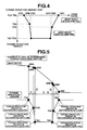
- FIG. 4 illustrates a map of torque-reduction amount showing the relationship between a torque-reduction amount and a gear ratio.
- This torque-reduction amount map is provided for each type of shifting, i.e. 1-3 shifting, 2-3 shifting, 3-4 shifting or the like, for example, to allow calculation of an optimum torque-reduction amount in accordance with each shifting.
- FIG. 5 is a time chart for setting a torque-reduction amount in accordance with a change in gear ratio and on the basis of the torque-reduction amount map as shown in FIG. 4.
- the gear ratios GRA, GRB, GRC, GRD, GRE, GRF are set as a changing point of a torque-reduction amount set gain to carry out control such that at start of torque-reduction control, torque is reduced gradually, whereas at completion of torque-reduction control, torque is regained gradually.
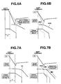
- FIGS. 6A-8B are time charts illustrating a vehicle-body acceleration G, gear ratio, torque-reduction amount TD when torque-reduction control in the embodiment is applied and when torque-reduction control in a comparative example is applied.
- FIG. 10 is a flow chart illustrating torque-reduction control in the comparative example.
- a step 201 When a shift command is output, at a step 201, torque-reduction control is started. At a step 202, engine torque is sustained as is, and then, at a step 203, it is determined whether or not a predetermined time T1 has elapsed. After a lapse of the predetermined time T1, at a step 204, engine torque is reduced gradually, and at a step 205, it is determined whether or not an actual gear ratio is equal to or smaller than the first set gear ratio G1. If the actual gear ratio is equal to or smaller than the first set gear ratio G1, at a step 206, engine torque is reduced up to a predetermined amount at a stroke.
- step 207 when the actual gear ratio is equal to the third set gear ratio G3, engine torque is regained at a stroke, achieving shortened shift time (refer to a time chart of an actual gear ratio and a torque-reduction amount in FIG. 11).
- FIGS. 6A and 6B show time charts for comparison with a case where a start timing of torque reduction is too advanced in the comparative example.
- a torque reduction is started. If a start timing is too advanced, the state occurs that acceleration of a torque portion lowered by a torque reduction is too reduced (refer hereafter to as drop).
- drop acceleration of a torque portion lowered by a torque reduction is too reduced.
- FIGS. 7A and 7B are time charts for comparing a case where a start timing of torque reduction is too delayed in the comparative example with the present embodiment.
- a torque reduction is started. If a start timing is too delayed, progression of the inertia phase is delayed to elongate shifting.
- a torque reduction when reaching the first set gear ratio GRA as in the embodiment in FIG. 7B, quick progression of the inertia phase can be achieved.
- FIGS. 8A and 8B are time charts for comparison with a case where a completion timing of torque reduction is too advanced in the comparative example.
- FIGS. 9A-9C are time charts illustrating as comparative examples a case where completion of torque-reduction control is carried out at a predetermined gradient as previously set by regaining a torque-reduction amount when reaching a predetermined gear ratio GR, and a case where completion of torque-reduction control is carried out by arranging change points of a torque-reduction amount set gain.
- the absolute value of the torque-reduction amount set gain is changed from a great value to a small value, allowing achievement of coincidence of the shifting completion timing and the torque-reduction control completion timing while regaining torque quickly, resulting in prevention of a shift shock and the like due to torque reduction.
- the torque-reduction amount set gain is previously set in an area of each gear ratio. Alternatively, it may be changed continuously with respect to a gear ratio.
Landscapes
- Engineering & Computer Science (AREA)
- Chemical & Material Sciences (AREA)
- Combustion & Propulsion (AREA)
- Mechanical Engineering (AREA)
- Transportation (AREA)
- General Engineering & Computer Science (AREA)
- Automation & Control Theory (AREA)
- Control Of Transmission Device (AREA)
Abstract
Description
Claims (4)
- A system for controlling a torque reduction at shifting for an automatic transmission, the system comprising:torque changing means for changing an output torque of a prime mover;shift-state detecting means for detecting a shift state of the automatic transmission shift-controlled by shift control means in accordance with running conditions including a driving state; andtorque-reduction control means for reducing, when detecting start of an upshifting by said shift-state detecting means, the output torque by said torque changing means during a period from this detection to completion of the upshifting, characterized in thatthere arrange actual gear-ratio detecting means for detecting an actual gear ratio out of input rotation and output rotation of the automatic transmission, and torque-reduction amount computing means for calculating a torque-reduction amount out of a torque-reduction set gain set previously, which is a rate of change of the torque-reduction amount with respect to a change in gear ratio, and the detected actual gear ratio.
- The system for controlling a torque reduction at shifting for an automatic transmission as specified in claim 1, characterized in that said torque-reduction amount computing means include means having a plurality of set gear ratios and for changing the torque-reduction amount set gain by the detected actual gear ratio reaches the set gear ratio.
- The system for controlling a torque reduction at shifting for an automatic transmission as specified in claim 1 or 2, characterized in that
said torque-reduction amount computing means include means having a plurality of set gear ratios corresponding to immediately after start of shifting and for changing an absolute value of said torque-reduction amount set gain to be greater as shifting progresses and putting said torque-reduction amount set gain to zero when said actual gear ratio reaches the set gear ratio of zero gain to maintain the torque-reduction amount constant. - The system for controlling a torque reduction at shifting for an automatic transmission as specified in claims 1 through 3, characterized in that
said torque-reduction amount computing means include means having a plurality of set gear ratios corresponding to immediately before completion of shifting and for changing the absolute value of said torque-reduction amount set gain to be smaller as shifting progresses.
Applications Claiming Priority (3)
| Application Number | Priority Date | Filing Date | Title |
|---|---|---|---|
| JP2001302942 | 2001-09-28 | ||
| JP2001302942 | 2001-09-28 | ||
| PCT/JP2002/010061 WO2003029697A1 (en) | 2001-09-28 | 2002-09-27 | Gear-shift torque down control device of automatic transmission |
Publications (3)
| Publication Number | Publication Date |
|---|---|
| EP1431622A1 true EP1431622A1 (en) | 2004-06-23 |
| EP1431622A4 EP1431622A4 (en) | 2007-07-04 |
| EP1431622B1 EP1431622B1 (en) | 2009-11-11 |
Family
ID=19123099
Family Applications (1)
| Application Number | Title | Priority Date | Filing Date |
|---|---|---|---|
| EP02768115A Expired - Lifetime EP1431622B1 (en) | 2001-09-28 | 2002-09-27 | Gear-shift torque down control device of automatic transmission |
Country Status (5)
| Country | Link |
|---|---|
| US (1) | US6991583B2 (en) |
| EP (1) | EP1431622B1 (en) |
| JP (1) | JPWO2003029697A1 (en) |
| DE (1) | DE60234360D1 (en) |
| WO (1) | WO2003029697A1 (en) |
Cited By (1)
| Publication number | Priority date | Publication date | Assignee | Title |
|---|---|---|---|---|
| CN101612935A (en) * | 2008-06-25 | 2009-12-30 | 福特环球技术公司 | The transmission schedule of multi-stroke engine |
Families Citing this family (5)
| Publication number | Priority date | Publication date | Assignee | Title |
|---|---|---|---|---|
| US7762925B2 (en) * | 2006-12-29 | 2010-07-27 | Honda Motor Co., Ltd. | Engine power reduction during automatic transmission shifting |
| US9404575B2 (en) * | 2007-06-29 | 2016-08-02 | GM Global Technology Operations LLC | Transmission upshift flare detection and mitigation |
| US8096920B2 (en) * | 2008-06-25 | 2012-01-17 | Ford Global Technologies, Llc | Transmission scheduling for multi-stroke engine |
| US8442732B1 (en) | 2011-10-27 | 2013-05-14 | Eaton Corporation | Method and system for determining a driveline ratio for a powertrain having an auxiliary transmission |
| US9423022B2 (en) | 2014-07-14 | 2016-08-23 | Honda Motor Co., Ltd. | Apparatus and methods for determining vehicular transmission output torque |
Family Cites Families (8)
| Publication number | Priority date | Publication date | Assignee | Title |
|---|---|---|---|---|
| JPS59126072A (en) * | 1983-01-07 | 1984-07-20 | Toyota Motor Corp | Speed change control of vehicle equipped with automatic speed change gear |
| EP0182376B1 (en) | 1984-11-22 | 1991-05-08 | Nissan Motor Co., Ltd. | Device for controlling shift in automatic transmission |
| JPH0245628A (en) * | 1988-08-08 | 1990-02-15 | Nissan Motor Co Ltd | Synthetic controller for lightening speed change shock for power train |
| JPH08156652A (en) * | 1994-12-07 | 1996-06-18 | Hitachi Ltd | Vehicle drive torque control device |
| US5562567A (en) * | 1995-06-30 | 1996-10-08 | General Motors Corporation | Shift torque management |
| JPH1047469A (en) * | 1996-07-31 | 1998-02-20 | Jatco Corp | Upshift control device for automatic transmission |
| JP3282017B2 (en) * | 1996-09-19 | 2002-05-13 | 株式会社ユニシアジェックス | Shift shock reduction device for vehicles |
| JP3252731B2 (en) * | 1996-12-25 | 2002-02-04 | アイシン・エィ・ダブリュ株式会社 | Transmission control device for automatic transmission |
-
2002
- 2002-09-27 DE DE60234360T patent/DE60234360D1/en not_active Expired - Lifetime
- 2002-09-27 WO PCT/JP2002/010061 patent/WO2003029697A1/en not_active Ceased
- 2002-09-27 EP EP02768115A patent/EP1431622B1/en not_active Expired - Lifetime
- 2002-09-27 JP JP2003532876A patent/JPWO2003029697A1/en active Pending
- 2002-09-27 US US10/489,957 patent/US6991583B2/en not_active Expired - Lifetime
Cited By (2)
| Publication number | Priority date | Publication date | Assignee | Title |
|---|---|---|---|---|
| CN101612935A (en) * | 2008-06-25 | 2009-12-30 | 福特环球技术公司 | The transmission schedule of multi-stroke engine |
| CN101612935B (en) * | 2008-06-25 | 2013-05-08 | 福特环球技术公司 | Transmission schedule for multi-stroke engine |
Also Published As
| Publication number | Publication date |
|---|---|
| US6991583B2 (en) | 2006-01-31 |
| DE60234360D1 (en) | 2009-12-24 |
| WO2003029697A1 (en) | 2003-04-10 |
| JPWO2003029697A1 (en) | 2005-01-20 |
| EP1431622A4 (en) | 2007-07-04 |
| US20040235617A1 (en) | 2004-11-25 |
| EP1431622B1 (en) | 2009-11-11 |
Similar Documents
| Publication | Publication Date | Title |
|---|---|---|
| EP1647741A1 (en) | Engine torque control device | |
| JPH0712809B2 (en) | Integrated control device for automatic transmission and engine | |
| JPH0481658B2 (en) | ||
| KR100713054B1 (en) | Engine torque control device | |
| EP3061996B1 (en) | Control device for continuously variable transmission | |
| EP0805060B1 (en) | Control system for internal combustion engines for automotive vehicles | |
| JP3746100B2 (en) | Shift control device and control method | |
| JPH0245628A (en) | Synthetic controller for lightening speed change shock for power train | |
| US6991583B2 (en) | System for controlling torque reduction at shifting for automatic transmission | |
| US7287631B2 (en) | Lock-up control for torque converter | |
| US5800306A (en) | Method and system for controlling automatic power transmission | |
| KR100354004B1 (en) | Method for engine controlling of vehicle | |
| JP3304654B2 (en) | Engine torque control device | |
| JP3009781B2 (en) | Control device for automatic transmission | |
| KR100491566B1 (en) | Shift control system for automatic transmission | |
| JPH0759904B2 (en) | Engine control device in vehicle with automatic transmission | |
| US7278952B2 (en) | Terminating or disallowing signals to increase a throttle opening | |
| JP2003343302A (en) | Control device for engine and automatic transmission | |
| KR100494887B1 (en) | Method of decreasing engine torgue under kick-down for an automatic transmission in vehicles | |
| KR100290342B1 (en) | Shift control method during power-off upshift of automatic transmission | |
| JPH08177541A (en) | Engine torque control device | |
| JP2925769B2 (en) | Engine control device | |
| KR20030044097A (en) | Apparatus for engine torque reduction controlling in automatic transmission and method thereof | |
| JPS6367455A (en) | Line pressure control device for continuously variable transmission | |
| EP1447259A2 (en) | Power control apparatus and power control method for internal combustion engines |
Legal Events
| Date | Code | Title | Description |
|---|---|---|---|
| PUAI | Public reference made under article 153(3) epc to a published international application that has entered the european phase |
Free format text: ORIGINAL CODE: 0009012 |
|
| 17P | Request for examination filed |
Effective date: 20040318 |
|
| AK | Designated contracting states |
Kind code of ref document: A1 Designated state(s): AT BE BG CH CY CZ DE DK EE ES FI FR GB GR IE IT LI LU MC NL PT SE SK TR |
|
| A4 | Supplementary search report drawn up and despatched |
Effective date: 20070601 |
|
| 17Q | First examination report despatched |
Effective date: 20071001 |
|
| GRAP | Despatch of communication of intention to grant a patent |
Free format text: ORIGINAL CODE: EPIDOSNIGR1 |
|
| RIC1 | Information provided on ipc code assigned before grant |
Ipc: F16H 59/46 20060101ALI20090311BHEP Ipc: F16H 61/04 20060101AFI20090311BHEP |
|
| GRAS | Grant fee paid |
Free format text: ORIGINAL CODE: EPIDOSNIGR3 |
|
| GRAA | (expected) grant |
Free format text: ORIGINAL CODE: 0009210 |
|
| AK | Designated contracting states |
Kind code of ref document: B1 Designated state(s): DE FR GB |
|
| REG | Reference to a national code |
Ref country code: GB Ref legal event code: FG4D |
|
| REF | Corresponds to: |
Ref document number: 60234360 Country of ref document: DE Date of ref document: 20091224 Kind code of ref document: P |
|
| PLBE | No opposition filed within time limit |
Free format text: ORIGINAL CODE: 0009261 |
|
| STAA | Information on the status of an ep patent application or granted ep patent |
Free format text: STATUS: NO OPPOSITION FILED WITHIN TIME LIMIT |
|
| 26N | No opposition filed |
Effective date: 20100812 |
|
| REG | Reference to a national code |
Ref country code: FR Ref legal event code: PLFP Year of fee payment: 15 |
|
| REG | Reference to a national code |
Ref country code: FR Ref legal event code: PLFP Year of fee payment: 16 |
|
| REG | Reference to a national code |
Ref country code: FR Ref legal event code: PLFP Year of fee payment: 17 |
|
| PGFP | Annual fee paid to national office [announced via postgrant information from national office to epo] |
Ref country code: DE Payment date: 20180911 Year of fee payment: 17 Ref country code: FR Payment date: 20180813 Year of fee payment: 17 |
|
| PGFP | Annual fee paid to national office [announced via postgrant information from national office to epo] |
Ref country code: GB Payment date: 20180926 Year of fee payment: 17 |
|
| REG | Reference to a national code |
Ref country code: DE Ref legal event code: R119 Ref document number: 60234360 Country of ref document: DE |
|
| PG25 | Lapsed in a contracting state [announced via postgrant information from national office to epo] |
Ref country code: DE Free format text: LAPSE BECAUSE OF NON-PAYMENT OF DUE FEES Effective date: 20200401 |
|
| GBPC | Gb: european patent ceased through non-payment of renewal fee |
Effective date: 20190927 |
|
| PG25 | Lapsed in a contracting state [announced via postgrant information from national office to epo] |
Ref country code: FR Free format text: LAPSE BECAUSE OF NON-PAYMENT OF DUE FEES Effective date: 20190930 Ref country code: GB Free format text: LAPSE BECAUSE OF NON-PAYMENT OF DUE FEES Effective date: 20190927 |