EP1431544A1 - Start assister of fuel injection pump - Google Patents
Start assister of fuel injection pump Download PDFInfo
- Publication number
- EP1431544A1 EP1431544A1 EP02760662A EP02760662A EP1431544A1 EP 1431544 A1 EP1431544 A1 EP 1431544A1 EP 02760662 A EP02760662 A EP 02760662A EP 02760662 A EP02760662 A EP 02760662A EP 1431544 A1 EP1431544 A1 EP 1431544A1
- Authority
- EP
- European Patent Office
- Prior art keywords
- piston
- fuel injection
- fuel
- housing
- chamber
- Prior art date
- Legal status (The legal status is an assumption and is not a legal conclusion. Google has not performed a legal analysis and makes no representation as to the accuracy of the status listed.)
- Granted
Links
- 239000000446 fuel Substances 0.000 title claims abstract description 129
- 238000002347 injection Methods 0.000 title claims abstract description 78
- 239000007924 injection Substances 0.000 title claims abstract description 78
- 239000000295 fuel oil Substances 0.000 claims description 21
- 238000007906 compression Methods 0.000 description 14
- 230000002708 enhancing effect Effects 0.000 description 9
- 230000000694 effects Effects 0.000 description 5
- 230000001965 increasing effect Effects 0.000 description 5
- 238000007789 sealing Methods 0.000 description 5
- 239000000498 cooling water Substances 0.000 description 4
- 238000007599 discharging Methods 0.000 description 4
- 239000003921 oil Substances 0.000 description 4
- 230000006866 deterioration Effects 0.000 description 3
- 230000008602 contraction Effects 0.000 description 2
- 230000003111 delayed effect Effects 0.000 description 2
- 239000002828 fuel tank Substances 0.000 description 2
- 230000002093 peripheral effect Effects 0.000 description 2
- 238000003825 pressing Methods 0.000 description 2
- 230000002542 deteriorative effect Effects 0.000 description 1
- 239000013013 elastic material Substances 0.000 description 1
- 238000007726 management method Methods 0.000 description 1
- 230000000149 penetrating effect Effects 0.000 description 1
- 239000007858 starting material Substances 0.000 description 1
- 229920003002 synthetic resin Polymers 0.000 description 1
- 239000000057 synthetic resin Substances 0.000 description 1
Images




Classifications
-
- F—MECHANICAL ENGINEERING; LIGHTING; HEATING; WEAPONS; BLASTING
- F02—COMBUSTION ENGINES; HOT-GAS OR COMBUSTION-PRODUCT ENGINE PLANTS
- F02M—SUPPLYING COMBUSTION ENGINES IN GENERAL WITH COMBUSTIBLE MIXTURES OR CONSTITUENTS THEREOF
- F02M59/00—Pumps specially adapted for fuel-injection and not provided for in groups F02M39/00 -F02M57/00, e.g. rotary cylinder-block type of pumps
- F02M59/38—Pumps characterised by adaptations to special uses or conditions
- F02M59/42—Pumps characterised by adaptations to special uses or conditions for starting of engines
-
- F—MECHANICAL ENGINEERING; LIGHTING; HEATING; WEAPONS; BLASTING
- F02—COMBUSTION ENGINES; HOT-GAS OR COMBUSTION-PRODUCT ENGINE PLANTS
- F02D—CONTROLLING COMBUSTION ENGINES
- F02D1/00—Controlling fuel-injection pumps, e.g. of high pressure injection type
- F02D1/02—Controlling fuel-injection pumps, e.g. of high pressure injection type not restricted to adjustment of injection timing, e.g. varying amount of fuel delivered
-
- F—MECHANICAL ENGINEERING; LIGHTING; HEATING; WEAPONS; BLASTING
- F02—COMBUSTION ENGINES; HOT-GAS OR COMBUSTION-PRODUCT ENGINE PLANTS
- F02D—CONTROLLING COMBUSTION ENGINES
- F02D1/00—Controlling fuel-injection pumps, e.g. of high pressure injection type
- F02D1/02—Controlling fuel-injection pumps, e.g. of high pressure injection type not restricted to adjustment of injection timing, e.g. varying amount of fuel delivered
- F02D1/025—Controlling fuel-injection pumps, e.g. of high pressure injection type not restricted to adjustment of injection timing, e.g. varying amount of fuel delivered by means dependent on engine working temperature
-
- F—MECHANICAL ENGINEERING; LIGHTING; HEATING; WEAPONS; BLASTING
- F02—COMBUSTION ENGINES; HOT-GAS OR COMBUSTION-PRODUCT ENGINE PLANTS
- F02M—SUPPLYING COMBUSTION ENGINES IN GENERAL WITH COMBUSTIBLE MIXTURES OR CONSTITUENTS THEREOF
- F02M41/00—Fuel-injection apparatus with two or more injectors fed from a common pressure-source sequentially by means of a distributor
- F02M41/02—Fuel-injection apparatus with two or more injectors fed from a common pressure-source sequentially by means of a distributor the distributor being spaced from pumping elements
- F02M41/06—Fuel-injection apparatus with two or more injectors fed from a common pressure-source sequentially by means of a distributor the distributor being spaced from pumping elements the distributor rotating
-
- F—MECHANICAL ENGINEERING; LIGHTING; HEATING; WEAPONS; BLASTING
- F02—COMBUSTION ENGINES; HOT-GAS OR COMBUSTION-PRODUCT ENGINE PLANTS
- F02M—SUPPLYING COMBUSTION ENGINES IN GENERAL WITH COMBUSTIBLE MIXTURES OR CONSTITUENTS THEREOF
- F02M59/00—Pumps specially adapted for fuel-injection and not provided for in groups F02M39/00 -F02M57/00, e.g. rotary cylinder-block type of pumps
- F02M59/20—Varying fuel delivery in quantity or timing
- F02M59/24—Varying fuel delivery in quantity or timing with constant-length-stroke pistons having variable effective portion of stroke
- F02M59/26—Varying fuel delivery in quantity or timing with constant-length-stroke pistons having variable effective portion of stroke caused by movements of pistons relative to their cylinders
- F02M59/265—Varying fuel delivery in quantity or timing with constant-length-stroke pistons having variable effective portion of stroke caused by movements of pistons relative to their cylinders characterised by the arrangement or form of spill port of spill contour on the piston
Definitions
- the present invention relates to a structure of a start assister of a fuel injection pump.
- start assister of a fuel injection pump comprising a start-advancing mechanism for advancing a fuel injection timing by closing a sub port in a plunger part of the fuel injection pump.
- This conventional start assister has a drain passage formed in a housing to be connected to the sub port.
- the drain passage is opened and closed, i.e., the sub port is opened and closed by a peripheral portion of the piston, wherein the fuel injection timing is advanced by closing the sub port.
- An actuator such as a temperature-sensing member, a solenoid, or the like is installed in the start assister.
- the sliding of the piston for opening and closing the sub port depends on expansion and contraction movement of a pin of the actuator.
- the housing In the housing are formed upper and lower chambers over and under the piston, and bored respective passages for connecting the upper and lower chambers to a fuel gallery.
- the pin of the temperature-sensing member is arranged in higher-pressured one of the upper and lower chambers over and under the piston. Therefore, the temperature-sensing member is subjected to change of pressure in the corresponding chamber and liable to be permeated by fuel oil in the corresponding chamber, thereby being possible to be damaged or deteriorated.
- the temperature-sensing member, solenoid, or the like, serving as the actuator is fixedly installed in the housing.
- the standardized start assister is unable to have the installed actuator replaced with another type actuator, thereby being difficult to correspond to various demands.
- the inlay-gap between the housing and piston requires complicated processing and management as precise as the inlay-gap between the plunger and the plunger barrel.
- a start assister of a fuel injection pump comprises a piston slidably installed in a housing, an upper chamber formed over the piston, a lower chamber formed under the piston, and a sub port opened and closed by sliding of the piston, wherein a fuel injection timing is advanced by closing the sub port.
- the start assister is characterized by a temperature-sensing member for sliding the piston being arranged on one side in the piston-sliding direction, a telescopic pin of the temperature-sensing member arranged in a low-pressure chamber divided into the upper chamber and the lower chamber, and a connection pin interposed between the telescopic pin and the piston.
- connection pin connecting the piston to the telescopic pin of the temperature-sensing member may be suitably selected in its diametrical size so as to reduce fluctuation of pressure in the upper and lower chambers causing load on the temperature-sensing member, thereby preventing functional deterioration and damage of the temperature-sensing member and enhancing its reliability.
- a stopper may be formed by either the telescopic pin or the connection pin so as to prevent the telescopic pin from being contracted shorter than its telescopic stroke.
- the interior of the temperature-sensing member such as a sleeve, is free from thrust force from the connection pin in the contracting direction, thereby preventing functional deterioration and damage of the temperature-sensing member and enhancing its reliability.
- a seal member may be interposed between the stopper and the temperature-sensing member so as to seal an inside of a main body of the temperature-sensing member from the lower-pressure chamber.
- a start assister of a fuel injection pump comprises function members.
- a piston slidably inlayed into a housing, and an actuator installed in the housing so as to slide the piston serve as the function members.
- a temperature-sensing member, a solenoid or the like serves as the actuator.
- a sub port is opened and closed by sliding of the piston.
- a fuel injection timing is advanced by closing the sub port.
- the function members installed in the housing are optionally exchangeable.
- the function members of the start assister may be assembled together so as to make a unit detachably installed in the housing.
- the units can be provided so that each of them ensures its function and precision, thereby enhancing its reliability.
- the units having different actuators such as the temperature-sensing member and the solenoid can be prepared corresponding to various uses, and one of the units is selectively installed so as to provide a suitable structure of advancing fuel injection timing.
- a start assister of a fuel injection pump comprises: a sub port for draining a part of fuel oil admitted into a plunger barrel from a fuel gallery; a drain passage connected to the sub port; a piston for opening and closing the drain passage being slidably inlayed into a housing so as to have an inlay-gap between the piston and the housing, wherein the piston closes the sub port so as to advance fuel injection timing; an upper chamber formed over the piston; and a lower chamber formed under the piston.
- the upper chamber and the lower chamber communicate with the fuel gallery through only the inlay-gap between the housing and the piston.
- a high-pressure chamber may be formed in the housing so as to be open toward a side surface of the piston opposite to the fuel gallery and to communicate with the upper chamber and the lower chamber through the inlay-gap between the housing and the piston.
- the piston can be pressed against an inner side surface of the inlay hole facing the open side of the fuel gallery so as to improve the sealing of the lower and upper chambers from the fuel gallery, thereby keeping the pressure accumulated in the lower and upper chambers and enhancing the efficiency of advancing fuel injection timing. Even if the volume of the inlay-gap between the inlay-hole and the piston changes, the enhanced sealing between the fuel gallery and the upper and lower chambers is still ensured so as to have steady property of advancing fuel injection timing.
- a plunger barrel 8 is inlaid into a housing H, and a plunger 7 is vertically slidably inserted in the plunger barrel 8.
- the plunger 7 is biased downward and vertically reciprocated by rotating cam (not shown) below the plunger 7.
- Fuel oil reserved in a fuel tank is supplied to a fuel gallery 43 by a trochoid pump.
- a fuel-compression chamber 44 for applying pressure to the inducted fuel is formed above the plunger 7.
- a main port (not shown) formed in the plunger barrel 8 can be brought into communication with the fuel-compression chamber 44.
- the main port communicates with the fuel gallery 43 through a fuel-supply oil passage so as to be constantly supplied with fuel.
- Fuel inducted into the fuel-compression chamber 44 from the fuel gallery 43 through the main port is pressurized by the plunger 7 sliding upward so as to be discharged to a distributor shaft 9 through a fuel-discharging passage 21.
- Fuel oil is distributed to plural delivery valves 12 by rotating the distributor shaft 9, and the fuel oil supplied to each of the delivery valves 12 is discharged to an injection nozzle so as to be injected.
- a reference numeral 16 designates a plunger lead for setting an effective stroke of the plunger 7 on discharging fuel.
- a sub port 42 is formed in the plunger barrel 8, and a sub lead 7b is formed at a top portion 7a of the plunger 7, so that the sub lead 7b can be brought into communication with the sub port 42 at a certain rotation range of the plunger 7.
- the fuel compression-chamber 44 may be brought into communication with the sub port 42 through the sub lead 7b.
- An inlay-hole Ha is bored downward in the housing H beside the plunger barrel 8.
- a space under the piston 46 in the inlay-hole Ha is made as a lower chamber 48, and a space over the piston 46 is made as an upper chamber 49.
- the lower chamber 48 communicates with the upper chamber 49 through a communication hole 46a formed at the top surface of the piston 46.
- the lower chamber 48 communicates with the fuel gallery 43.
- An oil passage 81 in communication with the sub port 42 is arranged in the radial direction in the plunger barrel 8, and the oil passage 81 communicates with the inlay-hole Ha through a drain passage 83 formed in the housing H.
- the piston 46 is biased upward by a spring 51.
- a thermo-element 61 serving as a temperature-sensing member is arranged above the piston 46, and it is fastened to a supporter 41 inserted into the inlay-hole Ha.
- thermo-element 61 wax 61c having mobility is enclosed in a main body 61d of the thermo-element 61, and the wax 61c is sealed by a sleeve 61b made of elastic material.
- a sleeve 61b made of elastic material.
- a telescopic piston 61a Into a cylindrical hollow formed in the sleeve 61b is slidably fitted a telescopic piston 61a.
- the piston 61a is axially movably supported in a cover 61e of the main body 61d.
- a cooling water chamber 63 through which cooling water flows is formed around the portion of the main body 61d enclosing the wax 61c, so that the expansion/contraction of the wax 61c depends on the temperature of cooling water flowing through the cooling water chamber 63.
- thermo-element 61 has the telescopic pin 61a extended downward, and the telescopic pin 61a abuts against the top surface of the piston 46 with a connection pin 62 between the telescopic pin 61a and the top surface of the piston 46.
- a low-pressured chamber 50 connected to a fuel tank is formed inside the supporter 41 supporting the thermo-element 61.
- the telescopic pin 61a, the main body 61d, and the cover 61e are disposed at their lower end portions in the low-pressured chamber 50.
- the supporter 41 separates the low-pressured chamber 50 from the upper and lower chambers 49 and 48 in communication with the high-pressured fuel gallery 43.
- the fuel gallery 43 has an opening toward the inlay hale Ha so as to communicate with the lower chamber 48.
- the drain passage 83 also has an opening toward the inlay hale Ha, which is closed by a side surface of the upwardly slid piston 46 shown in Fig.1.
- the upwardly slid piston 46 separates the fuel gallery 43 from the drain passage 83. If the telescopic pin 61a of the thermo-element 61 is extended to slide the piston 46 downward as shown in Fig.2, the drain passage 83 is opened to the upper chamber 49 so as to be brought into communication with the fuel gallery 43 through the communication hole 46 and a communication hole 46a' formed at the side surface of the piston 46.
- a start assister 10 of the fuel injection pump 1 comprises the piston 46, the lower chamber 48, the upper chamber 49, the low-pressured chamber 50, the thermo-element 61, the spring 51, and the like.
- the piston 46 is slid upward to close the sub port 42, whereby the beginning of fuel-discharging is not delayed, i.e., the fuel injection timing is advanced.
- thermo-element 61 While the piston 46, operated with the telescopic pin 61a of the thermo-element 61 through the connection pin 61, slides in the upper and lower chambers 49 and 48 in communication with the fuel gallery 43, components of the thermo-element 61, i.e., the telescopic pin 61a, the main body 61d, the cover 61e, and the like are arranged in the low-pressured chamber 50 separated from the upper and lower chambers 49 and 48 so as not to be subjected to fluctuation of pressure generated in the upper and lower chambers 49 and 48. Namely, the components of the thermo-element 60 are subjected to only pressure in the low-pressure chamber 50 almost as high as the atmospheric pressure.
- the pulsating pressure in the fuel gallery 43 for example, which occurs by the trochoid pump for feeding fuel oil, is transmitted to the upper and lower chambers 49 and 48, thereby causing the fluctuation of pressure applied to the upper and lower chambers 49 and 48.
- thermo-element 61 is prevented from being functionally deteriorated and being damaged, thereby enhancing its reliability.
- connection pin 62 having a diameter suitable to be connected to the telescopic pin 61a of the thermo-element 61 and the piston 46, load onto the thermo-element 60 caused by the fluctuation of pressure in the upper and lower chambers 49 and 48 can be lowered so as to prevent the thermo-element 61 from being functionally deteriorated and being damaged, thereby enhancing its reliability.
- a stopper 61f is formed at the lower end of the telescopic pin 61a.
- the stopper 61f abuts against the bottom end surface of the cover 61e so as to keep the telescopic pin 61a from further sliding in its contracting direction, whereby the contracting force of the telescopic pin 61a to be applied to the connection pin 62 is received by the stopper 61f and the bottom end surface of the cover 61e.
- thermo-element 61 is prevented from being functionally deteriorated and being damaged, thereby enhancing its reliability.
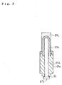
- a seal member 65 made of rubber, synthetic resin or the like may be interposed between the stopper 61f and the bottom surface of the cover 61e, as shown in Fig. 3.
- the seal member 65 is attached to the stopper 61f side, for example, but it may be attached to the bottom surface of the cover 61e.
- the wax 61c does not press the sleeve 61b in the direction to push out the piston 61a, so that fuel oil is apt to be introduced into an opening between the telescopic pin 61a and the sleeve 61b when fuel oil pressure is applied.
- the seal member 65 interposed between the stopper 61f and the bottom surface of the cover 61e prevents the entrance of fuel oil into the opening between the telescopic pin 61a and the sleeve 61b.
- the entrance of fuel oil into the opening between the telescopic pin 61a and the sleeve 61b changes the bottom end position of the contracted telescopic pin 61a so as to change the opening and closing timings of the sub port.
- the above arrangement prevents this entrance of fuel oil functionally deteriorating and damaging the thermo-element 61, thereby enhancing reliability of the thermo-element 61.
- thermo-element 61 is arranged above the piston 46 in this embodiment. Alternatively, the thermo-element 61 may be arranged below the piston 46.
- the present start assister 10 can have optional exchange of only an actuator for driving the piston 46.
- the start assister 10 having the housing H in which the thermo-element 60 serving as the actuator for driving the piston 46 is installed as shown in Fig. 4 can change its specification only by replacing the thermo-element 60 with a solenoid 71 shown in Fig.5.
- thermo-element 61 and the solenoid 71 are screwed into the housing H.
- the thermo-element 61 and solenoid 71 have respective main bodies 61 and 71, which are provided at their lower portions with standardized tapped holes.
- thermo-element 61 the solenoid 71 and the like serve as exchangeable actuators, one of which can be selectively installed in the housing H, thereby providing a fuel injection timing advancing structure suitable to any of various uses.
- the piston 46, the thermo-element 61 and others serving as members constituting the start assister 10 may be assembled together in a spindle barrel 75 so as to form a unit detachably fitted into the housing H.
- the unit is installed by screwing the spindle barrel 75 into the housing H, so as to constitute the low-pressure chamber in the spindle barrel 75.
- the piston 46 is slidably inlayed into a recessed portion 75a at the bottom end of the spindle barrel 75, so as to be driven by the telescopic pin 61a of the thermo-element 61.
- the solenoid 71 serves as the actuator for driving the piston 46, as shown in Fig.7
- the piston 46', the solenoid 71, and the like serving as members constituting the start assister 10 may be assembled integrally in a spindle barrel 75' so as to form a unit detachably installed in the housing H.
- the unit is installed by screwing the spindle barrel 75' to the housing H.
- the piston 46' is slidably inlayed into an inlay-hole 75a' the spindle barrel 75', so as to be driven by the solenoid 71.
- the drain passage 83 When the piston 46' is slid upward by the spring 51, the drain passage 83 is closed by a periphery of the piston 46'. When the piston 46' slides downward, the drain passage 83 is brought into communication with the fuel gallery 43 through a communication hole 46e' of the piston 46'.
- the unit as assembly of the piston 46, the thermo-element 61 and the like in the spindle barrel 75 and the unit as assembly of the piston 46', the solenoid 71 and the like in the spindle barrel 75' are exchangeable corresponding to needs, so as to be installed in the housing H.
- the function members of the start assister 10 are unified so as to provide a unit having function and precision ensuring enhanced reliability.
- thermo-element and the solenoid Any suitable one of exchangeable various units having different actuators such as the thermo-element and the solenoid is selected and installed in the housing H so as to have injection-time-advancing control at start-up time corresponding to use.
- the fuel injection pump 1 shown in Fig. 7 has the plunger 7 portion configured almost similar to that of the above-mentioned fuel injection pump 1 shown in Figs. 1 and 2. Description of members of the fuel injection pump 1 and its start assister 10 shown in Fig. 7, which are designated by the same reference numerals with those of Figs. 1 and 2, are omitted.
- the inlay-hole Ha having a lower portion into which a timer piston 146 is vertically slidably inserted so as to have a predetermined inlay-gap S therebetween.
- a space under the timer piston 146 in the inlay-hole Ha is made as a lower chamber 148, and a space over the timer piston 146 is made as an upper chamber 149.
- the lower chamber 148 communicates with the upper chamber 149 through a communication hole 146a vertically penetrating the timer piston 146.
- the oil passage 81 in communication with the sub port 42 is arranged in the radial direction in the plunger barrel 8 so as to communicate with the inlay-hole Ha through the drain passage 83 formed in the housing H.
- the timer piston 146 is biased upward by a spring 151.
- a thermo-element 161 serving as a temperature-sensing member is arranged above the timer piston 146, and fastened to a supporter 141 inserted into the inlay-hole Ha.
- thermo-element 161 has a downwardly extended telescopic piston 161a abutting against the top surface of the timer piston 146 through a pin 161b.
- the telescopic pin 161a is contracted at a low temperature state where temperature is not higher than a preset temperature.
- the telescopic pin 161a is expanded so as to downwardly slide the timer piston 146 essentially slid upward by biasing of the spring 151.
- the timer piston 146 slides upward by the biasing force of the spring 151 so as to contract the telescopic pin 161a.
- the present start assister 10 of the fuel injection pump 1 comprises the timer piston 146, the lower chamber 148, the upper chamber 149, a high-pressure chamber 150, the communication passage 83, the spring 151, and the like.
- the fuel gallery 43 has an opening toward the inlay hale Ha, which is closed by the side surface of the timer piston 146.
- the drain passage 83 also has an opening toward the inlay hale Ha, which is closed by the side surface of the timer piston 146.
- the timer piston 146 In a state of the timer piston 146 having slid upward (shown in Fig. 8), the timer piston 146 separates the fuel gallery 43 from the drain passage 83.
- the telescopic pin 161a of the thermo-element 161 is expanded and the timer piston 146 slides downward, the fuel gallery 43 and the drain passage 83 are brought into communication with each other through a recessed groove 146b formed at a periphery of the timer piston 146.
- the high-pressure chamber 150 having an opening toward the side surface of the piston is formed in the housing H opposite to the fuel gallery 43.
- the inlay-gap S is ensured between the timer piston 146 and the housing H so as to bring the lower and upper chambers 148 and 149 into communication with the drain passage 83 through the inlay-gap S. Accordingly, when the sub port 42 is closed by the timer piston 146, fuel oil in the fuel-compression chamber 44 pressurized by the plunger 7 leaks out to the lower chamber 148 and the upper chamber 149 from the inlay-gap S, so that the pressure in the lower and upper chambers 148 and 149 is accumulated at the level of fuel injection pressure in the fuel-compression chamber 44.
- the high-pressure chamber 150 also communicates with the lower chamber 148 and the upper chamber 149 through the inlay-gap S so as to accumulate pressure leveled with the fuel injection pressure in the fuel-compression chamber 44.
- the lower chamber 148 and the upper chamber 149 communicate with the fuel gallery 43 through the inlay-gap S.
- the high-pressure chamber 150 accumulating the fuel injection pressure is arranged opposite to the fuel gallery 43, the pressure in the high-pressure chamber 150 presses the timer piston 146 toward the fuel gallery 43 side.
- the inlay-gap S between the timer piston 146 and the inner side surface of the inlay-hole Ha on the fuel gallery 43 side is shortened, so that both of them contact together, thereby improving the sealing between the fuel gallery 43 and the upper and lower chambers 149 and 148. Therefore, the pressure accumulated in the lower chamber 148, the upper chamber 149, and the high-pressure chamber 150 is maintained.
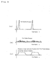
- Fig.9 (a) shows fuel injection pressure in the fuel-compression chamber 44 caused by the plunger 7
- Fig.9 (b) shows fuel gallery pressure
- Fig. 9 (c) shows pressure in the lower chamber 148, the upper chamber 149, and the high-pressure chamber 150.
- the fuel injection pressure leaks out through the inlay-gap S and accumulated in the lower chamber 148, the upper chamber 149, and the high-pressure chamber 150, so that the pressure in these chambers 148,149,150 is increased and then maintained for a determined time.
- the increased pressure in the lower chamber 148, the upper chamber 149, and the high-pressure chamber 150 is higher than the pressure in the fuel gallery 43.
- the injection pressure accumulated in the lower chamber 148, the upper chamber 149, and the high-pressure chamber 150 is kept at such a high level as to advance the injection timing at a degree larger than the advanced timing when the lower chamber 148 and the upper chamber 149 communicate with the fuel gallery 43 through drilled bores or the like.
- the high-pressure chamber 150 opposite to the fuel gallery 43 and open toward the side surface of the timer piston 146 is formed in the housing H so as to communicate with the upper and lower chambers 148 and 149 through the inlay-gap S between the housing H and the timer piston 146, thereby pressing the timer piston 146 against the inner side surface of the inlay-hole Ha facing the open side of the fuel gallery 43 so as to improve the sealing between the fuel gallery 43 and the upper and lower chambers 148 and 149.
- the pressure accumulated in the lower 148 chamber and the upper chamber 149 can be preserved so as to enhance the efficiency of advancing fuel injection timing.
- the start assister according to the present invention is applicable to a fuel injection pump used for a diesel engine and so forth.
Landscapes
- Engineering & Computer Science (AREA)
- Chemical & Material Sciences (AREA)
- Combustion & Propulsion (AREA)
- Mechanical Engineering (AREA)
- General Engineering & Computer Science (AREA)
- Fuel-Injection Apparatus (AREA)
- High-Pressure Fuel Injection Pump Control (AREA)
Abstract
Description
Claims (9)
- A start assister of a fuel injection pump, comprising:characterized by:a piston slidably installed in a housing;an upper chamber formed over the piston;a lower chamber formed under the piston; anda sub port opened and closed by sliding of the piston, wherein a fuel injection timing is advanced by closing the sub port,a temperature-sensing member for sliding the piston being arranged on one side in the piston-sliding direction;a telescopic pin of the temperature-sensing member arranged in a low-pressure chamber divided into the upper chamber and the lower chamber; anda connection pin interposed between the telescopic pin and the piston.
- The start assister of a fuel injection pump as set forth in claim 1, further comprising:a stopper formed by either the telescopic pin or the connection pin so as to prevent the telescopic pin from being contracted shorter than its telescopic stroke.
- The start assister of a fuel injection pump as set forth in claim 2, further comprising:a seal member interposed between the stopper and the temperature-sensing member so as to seal an inside of a main body of the temperature-sensing member from the lower-pressure chamber.
- A start assister of a fuel injection pump, comprising:characterized in that the function members installed in the housing are optionally exchangeable.function members including
a piston slidably inlayed into a housing, and
an actuator installed in the housing so as to slide the piston; anda sub port opened and closed by sliding of the piston, wherein fuel injection timing is advanced by closing the sub port, - The start assister of a fuel injection pump as set forth in claim 4, characterized in that the actuator is a temperature-sensing member.
- The start assister of a fuel injection pump as set forth in claim 4, characterized in that the actuator is a solenoid.
- The start assister of a fuel injection pump as set forth in claim 4, characterized in that the function members of the start assister are assembled together so as to make a unit detachably installed in the housing.
- A start assister of a fuel injection pump, comprising:characterized in that the upper chamber and the lower chamber communicate with the fuel gallery through only the inlay-gap between the housing and the piston.a sub port for draining a part of fuel oil admitted into a plunger barrel from a fuel gallery;a drain passage connected to the sub port;a piston for opening and closing the drain passage being slidably inlayed into a housing so as to have an inlay-gap between the piston and the housing, wherein the piston closes the sub port so as to advance fuel injection timing;an upper chamber formed over the piston; anda lower chamber formed under the piston;
- The start assister of a fuel injection pump as set forth in claim 8, characterized in that:the fuel gallery is open toward a side surface of the piston;a high-pressure chamber is formed in the housing so as to be open toward a side surface of the piston opposite to the fuel gallery and to communicate with the upper chamber and the lower chamber through the inlay-gap between the housing and the piston.
Applications Claiming Priority (5)
| Application Number | Priority Date | Filing Date | Title |
|---|---|---|---|
| JP2001300938A JP2003106173A (en) | 2001-09-28 | 2001-09-28 | Starting aids for fuel injection pump |
| JP2001300939A JP2003106240A (en) | 2001-09-28 | 2001-09-28 | Starting assist device for fuel injection pump |
| JP2001300939 | 2001-09-28 | ||
| JP2001300938 | 2001-09-28 | ||
| PCT/JP2002/008354 WO2003029631A1 (en) | 2001-09-28 | 2002-08-19 | Start assister of fuel injection pump |
Publications (3)
| Publication Number | Publication Date |
|---|---|
| EP1431544A1 true EP1431544A1 (en) | 2004-06-23 |
| EP1431544A4 EP1431544A4 (en) | 2010-06-02 |
| EP1431544B1 EP1431544B1 (en) | 2012-04-25 |
Family
ID=26623287
Family Applications (1)
| Application Number | Title | Priority Date | Filing Date |
|---|---|---|---|
| EP02760662A Expired - Lifetime EP1431544B1 (en) | 2001-09-28 | 2002-08-19 | Start assister of fuel injection pump |
Country Status (6)
| Country | Link |
|---|---|
| US (1) | US6880508B2 (en) |
| EP (1) | EP1431544B1 (en) |
| KR (1) | KR100847392B1 (en) |
| CN (1) | CN100374698C (en) |
| AT (1) | ATE555290T1 (en) |
| WO (1) | WO2003029631A1 (en) |
Families Citing this family (3)
| Publication number | Priority date | Publication date | Assignee | Title |
|---|---|---|---|---|
| JP3993841B2 (en) * | 2003-06-12 | 2007-10-17 | ヤンマー株式会社 | Fuel injection pump having a cold start advancement mechanism |
| JP4427523B2 (en) * | 2006-05-09 | 2010-03-10 | ヤンマー株式会社 | Fuel injection pump |
| US20090165761A1 (en) * | 2007-12-28 | 2009-07-02 | Curtis Lyle Fitchpatrick | Fuel control system having a cold start strategy |
Family Cites Families (10)
| Publication number | Priority date | Publication date | Assignee | Title |
|---|---|---|---|---|
| DE2648043C2 (en) * | 1976-10-23 | 1984-05-24 | Robert Bosch Gmbh, 7000 Stuttgart | Fuel injection pump for internal combustion engines |
| DE2716307A1 (en) * | 1977-04-13 | 1978-10-19 | Volkswagenwerk Ag | FUEL INJECTION PUMP FOR A SELF-IGNITING COMBUSTION ENGINE |
| DE2931908A1 (en) * | 1979-08-07 | 1981-02-26 | Bosch Gmbh Robert | FUEL INJECTION PUMP FOR INTERNAL COMBUSTION ENGINES |
| JPS60116853A (en) * | 1983-11-26 | 1985-06-24 | Diesel Kiki Co Ltd | Distributor type fuel injection pump |
| US4838232A (en) * | 1984-08-14 | 1989-06-13 | Ail Corporation | Fuel delivery control system |
| DE69332476T2 (en) * | 1992-08-20 | 2003-05-08 | Toyota Jidosha K.K., Toyota | Fuel injection regulator for internal combustion engines. |
| US5740782A (en) * | 1996-05-20 | 1998-04-21 | Lowi, Jr.; Alvin | Positive-displacement-metering, electro-hydraulic fuel injection system |
| JP3558486B2 (en) * | 1997-05-15 | 2004-08-25 | 日産ディーゼル工業株式会社 | Fuel injection control system for diesel engine |
| WO2000047888A1 (en) * | 1999-02-09 | 2000-08-17 | Hitachi, Ltd. | High-pressure fuel feed pump of internal combustion engine |
| JP4117079B2 (en) * | 1999-02-15 | 2008-07-09 | ヤンマー株式会社 | Injection timing control structure of distributed fuel injection pump |
-
2002
- 2002-08-19 WO PCT/JP2002/008354 patent/WO2003029631A1/en not_active Ceased
- 2002-08-19 CN CNB02818873XA patent/CN100374698C/en not_active Expired - Fee Related
- 2002-08-19 EP EP02760662A patent/EP1431544B1/en not_active Expired - Lifetime
- 2002-08-19 AT AT02760662T patent/ATE555290T1/en active
- 2002-08-19 KR KR1020047003448A patent/KR100847392B1/en not_active Expired - Fee Related
-
2004
- 2004-03-05 US US10/793,037 patent/US6880508B2/en not_active Expired - Lifetime
Non-Patent Citations (2)
| Title |
|---|
| No further relevant documents disclosed * |
| See also references of WO03029631A1 * |
Also Published As
| Publication number | Publication date |
|---|---|
| US6880508B2 (en) | 2005-04-19 |
| CN1558986A (en) | 2004-12-29 |
| US20040197198A1 (en) | 2004-10-07 |
| CN100374698C (en) | 2008-03-12 |
| EP1431544A4 (en) | 2010-06-02 |
| KR20040039339A (en) | 2004-05-10 |
| EP1431544B1 (en) | 2012-04-25 |
| KR100847392B1 (en) | 2008-07-18 |
| ATE555290T1 (en) | 2012-05-15 |
| WO2003029631A1 (en) | 2003-04-10 |
Similar Documents
| Publication | Publication Date | Title |
|---|---|---|
| US6662784B1 (en) | Pump assembly, valve and method | |
| US7954464B2 (en) | Cylinder head of an internal combustion engine having an electrohydraulic valve controller | |
| JP4681119B2 (en) | Radial piston pump for high pressure fuel generation | |
| JPS62107265A (en) | Electrostriction type oil pressure control valve | |
| US20120103179A1 (en) | Pump unit | |
| JP2002533612A (en) | Piston pump for high pressure fuel formation | |
| US6755625B2 (en) | Inlet throttle valve | |
| US4840160A (en) | Valve control device | |
| US5979415A (en) | Fuel injection pump with a hydraulically-spill valve | |
| US20070166174A1 (en) | Statically sealed high pressure fuel pump and method | |
| US6880508B2 (en) | Start assister of fuel injection pump | |
| KR20050059264A (en) | Valve for the control of fluids | |
| KR920702750A (en) | Fuel Dispensing Injection Pumps for Internal Combustion Engines | |
| US6622706B2 (en) | Pump, pump components and method | |
| JPH0712029A (en) | High pressure fuel pump | |
| US6427663B1 (en) | Inlet throttle pump assembly for diesel engine and method | |
| JP2584569B2 (en) | Hydraulic valve clearance compensator for internal combustion engine | |
| JP2001271726A (en) | Fuel pressurization pump | |
| JPH05149210A (en) | Fuel injection valve of internal combustion engine | |
| JPH11324855A (en) | Fuel injection device with oil seal | |
| CZ20022525A3 (en) | Fuel injection device and method for producing a system pressure within this injection device | |
| JPH0519575Y2 (en) | ||
| JP2003106173A (en) | Starting aids for fuel injection pump | |
| JP2003106240A (en) | Starting assist device for fuel injection pump | |
| JPS5936671Y2 (en) | Overflow valve of distribution type fuel injection pump |
Legal Events
| Date | Code | Title | Description |
|---|---|---|---|
| PUAI | Public reference made under article 153(3) epc to a published international application that has entered the european phase |
Free format text: ORIGINAL CODE: 0009012 |
|
| 17P | Request for examination filed |
Effective date: 20040220 |
|
| AK | Designated contracting states |
Kind code of ref document: A1 Designated state(s): AT BE CH CY DE DK ES FI FR GB GR IE IT LI LU MC NL PT SE |
|
| A4 | Supplementary search report drawn up and despatched |
Effective date: 20100503 |
|
| 17Q | First examination report despatched |
Effective date: 20101208 |
|
| GRAP | Despatch of communication of intention to grant a patent |
Free format text: ORIGINAL CODE: EPIDOSNIGR1 |
|
| GRAS | Grant fee paid |
Free format text: ORIGINAL CODE: EPIDOSNIGR3 |
|
| GRAA | (expected) grant |
Free format text: ORIGINAL CODE: 0009210 |
|
| AK | Designated contracting states |
Kind code of ref document: B1 Designated state(s): AT BE CH CY DE DK ES FI FR GB GR IE IT LI LU MC NL PT SE |
|
| REG | Reference to a national code |
Ref country code: GB Ref legal event code: FG4D |
|
| REG | Reference to a national code |
Ref country code: CH Ref legal event code: EP |
|
| REG | Reference to a national code |
Ref country code: AT Ref legal event code: REF Ref document number: 555290 Country of ref document: AT Kind code of ref document: T Effective date: 20120515 |
|
| REG | Reference to a national code |
Ref country code: IE Ref legal event code: FG4D |
|
| REG | Reference to a national code |
Ref country code: DE Ref legal event code: R096 Ref document number: 60242750 Country of ref document: DE Effective date: 20120621 |
|
| REG | Reference to a national code |
Ref country code: NL Ref legal event code: T3 |
|
| REG | Reference to a national code |
Ref country code: AT Ref legal event code: MK05 Ref document number: 555290 Country of ref document: AT Kind code of ref document: T Effective date: 20120425 |
|
| PG25 | Lapsed in a contracting state [announced via postgrant information from national office to epo] |
Ref country code: SE Free format text: LAPSE BECAUSE OF FAILURE TO SUBMIT A TRANSLATION OF THE DESCRIPTION OR TO PAY THE FEE WITHIN THE PRESCRIBED TIME-LIMIT Effective date: 20120425 Ref country code: CY Free format text: LAPSE BECAUSE OF FAILURE TO SUBMIT A TRANSLATION OF THE DESCRIPTION OR TO PAY THE FEE WITHIN THE PRESCRIBED TIME-LIMIT Effective date: 20120425 Ref country code: FI Free format text: LAPSE BECAUSE OF FAILURE TO SUBMIT A TRANSLATION OF THE DESCRIPTION OR TO PAY THE FEE WITHIN THE PRESCRIBED TIME-LIMIT Effective date: 20120425 |
|
| PG25 | Lapsed in a contracting state [announced via postgrant information from national office to epo] |
Ref country code: PT Free format text: LAPSE BECAUSE OF FAILURE TO SUBMIT A TRANSLATION OF THE DESCRIPTION OR TO PAY THE FEE WITHIN THE PRESCRIBED TIME-LIMIT Effective date: 20120827 Ref country code: GR Free format text: LAPSE BECAUSE OF FAILURE TO SUBMIT A TRANSLATION OF THE DESCRIPTION OR TO PAY THE FEE WITHIN THE PRESCRIBED TIME-LIMIT Effective date: 20120726 |
|
| PG25 | Lapsed in a contracting state [announced via postgrant information from national office to epo] |
Ref country code: BE Free format text: LAPSE BECAUSE OF FAILURE TO SUBMIT A TRANSLATION OF THE DESCRIPTION OR TO PAY THE FEE WITHIN THE PRESCRIBED TIME-LIMIT Effective date: 20120425 |
|
| PG25 | Lapsed in a contracting state [announced via postgrant information from national office to epo] |
Ref country code: DK Free format text: LAPSE BECAUSE OF FAILURE TO SUBMIT A TRANSLATION OF THE DESCRIPTION OR TO PAY THE FEE WITHIN THE PRESCRIBED TIME-LIMIT Effective date: 20120425 Ref country code: AT Free format text: LAPSE BECAUSE OF FAILURE TO SUBMIT A TRANSLATION OF THE DESCRIPTION OR TO PAY THE FEE WITHIN THE PRESCRIBED TIME-LIMIT Effective date: 20120425 |
|
| PLBE | No opposition filed within time limit |
Free format text: ORIGINAL CODE: 0009261 |
|
| STAA | Information on the status of an ep patent application or granted ep patent |
Free format text: STATUS: NO OPPOSITION FILED WITHIN TIME LIMIT |
|
| REG | Reference to a national code |
Ref country code: CH Ref legal event code: PL |
|
| PG25 | Lapsed in a contracting state [announced via postgrant information from national office to epo] |
Ref country code: MC Free format text: LAPSE BECAUSE OF NON-PAYMENT OF DUE FEES Effective date: 20120831 |
|
| 26N | No opposition filed |
Effective date: 20130128 |
|
| PG25 | Lapsed in a contracting state [announced via postgrant information from national office to epo] |
Ref country code: CH Free format text: LAPSE BECAUSE OF NON-PAYMENT OF DUE FEES Effective date: 20120831 Ref country code: ES Free format text: LAPSE BECAUSE OF FAILURE TO SUBMIT A TRANSLATION OF THE DESCRIPTION OR TO PAY THE FEE WITHIN THE PRESCRIBED TIME-LIMIT Effective date: 20120805 Ref country code: LI Free format text: LAPSE BECAUSE OF NON-PAYMENT OF DUE FEES Effective date: 20120831 |
|
| REG | Reference to a national code |
Ref country code: IE Ref legal event code: MM4A |
|
| REG | Reference to a national code |
Ref country code: DE Ref legal event code: R097 Ref document number: 60242750 Country of ref document: DE Effective date: 20130128 |
|
| PG25 | Lapsed in a contracting state [announced via postgrant information from national office to epo] |
Ref country code: IE Free format text: LAPSE BECAUSE OF NON-PAYMENT OF DUE FEES Effective date: 20120819 |
|
| PG25 | Lapsed in a contracting state [announced via postgrant information from national office to epo] |
Ref country code: LU Free format text: LAPSE BECAUSE OF NON-PAYMENT OF DUE FEES Effective date: 20120819 |
|
| REG | Reference to a national code |
Ref country code: FR Ref legal event code: PLFP Year of fee payment: 15 |
|
| PGFP | Annual fee paid to national office [announced via postgrant information from national office to epo] |
Ref country code: NL Payment date: 20160711 Year of fee payment: 15 |
|
| PGFP | Annual fee paid to national office [announced via postgrant information from national office to epo] |
Ref country code: IT Payment date: 20160822 Year of fee payment: 15 Ref country code: DE Payment date: 20160816 Year of fee payment: 15 Ref country code: GB Payment date: 20160817 Year of fee payment: 15 |
|
| PGFP | Annual fee paid to national office [announced via postgrant information from national office to epo] |
Ref country code: FR Payment date: 20160712 Year of fee payment: 15 |
|
| REG | Reference to a national code |
Ref country code: DE Ref legal event code: R119 Ref document number: 60242750 Country of ref document: DE |
|
| REG | Reference to a national code |
Ref country code: NL Ref legal event code: MM Effective date: 20170901 |
|
| GBPC | Gb: european patent ceased through non-payment of renewal fee |
Effective date: 20170819 |
|
| REG | Reference to a national code |
Ref country code: FR Ref legal event code: ST Effective date: 20180430 |
|
| PG25 | Lapsed in a contracting state [announced via postgrant information from national office to epo] |
Ref country code: NL Free format text: LAPSE BECAUSE OF NON-PAYMENT OF DUE FEES Effective date: 20170901 |
|
| PG25 | Lapsed in a contracting state [announced via postgrant information from national office to epo] |
Ref country code: DE Free format text: LAPSE BECAUSE OF NON-PAYMENT OF DUE FEES Effective date: 20180301 Ref country code: GB Free format text: LAPSE BECAUSE OF NON-PAYMENT OF DUE FEES Effective date: 20170819 |
|
| PG25 | Lapsed in a contracting state [announced via postgrant information from national office to epo] |
Ref country code: FR Free format text: LAPSE BECAUSE OF NON-PAYMENT OF DUE FEES Effective date: 20170831 Ref country code: IT Free format text: LAPSE BECAUSE OF NON-PAYMENT OF DUE FEES Effective date: 20170819 |