EP1431520A2 - Variable vane arm/unison ring attachment system - Google Patents
Variable vane arm/unison ring attachment system Download PDFInfo
- Publication number
- EP1431520A2 EP1431520A2 EP03257899A EP03257899A EP1431520A2 EP 1431520 A2 EP1431520 A2 EP 1431520A2 EP 03257899 A EP03257899 A EP 03257899A EP 03257899 A EP03257899 A EP 03257899A EP 1431520 A2 EP1431520 A2 EP 1431520A2
- Authority
- EP
- European Patent Office
- Prior art keywords
- vane
- arm
- bushing
- curvature
- radius
- Prior art date
- Legal status (The legal status is an assumption and is not a legal conclusion. Google has not performed a legal analysis and makes no representation as to the accuracy of the status listed.)
- Granted
Links
Images


Classifications
-
- F—MECHANICAL ENGINEERING; LIGHTING; HEATING; WEAPONS; BLASTING
- F01—MACHINES OR ENGINES IN GENERAL; ENGINE PLANTS IN GENERAL; STEAM ENGINES
- F01D—NON-POSITIVE DISPLACEMENT MACHINES OR ENGINES, e.g. STEAM TURBINES
- F01D17/00—Regulating or controlling by varying flow
- F01D17/10—Final actuators
- F01D17/12—Final actuators arranged in stator parts
- F01D17/14—Final actuators arranged in stator parts varying effective cross-sectional area of nozzles or guide conduits
- F01D17/16—Final actuators arranged in stator parts varying effective cross-sectional area of nozzles or guide conduits by means of nozzle vanes
- F01D17/162—Final actuators arranged in stator parts varying effective cross-sectional area of nozzles or guide conduits by means of nozzle vanes for axial flow, i.e. the vanes turning around axes which are essentially perpendicular to the rotor centre line
-
- F—MECHANICAL ENGINEERING; LIGHTING; HEATING; WEAPONS; BLASTING
- F05—INDEXING SCHEMES RELATING TO ENGINES OR PUMPS IN VARIOUS SUBCLASSES OF CLASSES F01-F04
- F05D—INDEXING SCHEME FOR ASPECTS RELATING TO NON-POSITIVE-DISPLACEMENT MACHINES OR ENGINES, GAS-TURBINES OR JET-PROPULSION PLANTS
- F05D2230/00—Manufacture
- F05D2230/60—Assembly methods
- F05D2230/64—Assembly methods using positioning or alignment devices for aligning or centring, e.g. pins
-
- F—MECHANICAL ENGINEERING; LIGHTING; HEATING; WEAPONS; BLASTING
- F05—INDEXING SCHEMES RELATING TO ENGINES OR PUMPS IN VARIOUS SUBCLASSES OF CLASSES F01-F04
- F05D—INDEXING SCHEME FOR ASPECTS RELATING TO NON-POSITIVE-DISPLACEMENT MACHINES OR ENGINES, GAS-TURBINES OR JET-PROPULSION PLANTS
- F05D2250/00—Geometry
- F05D2250/20—Three-dimensional
- F05D2250/29—Three-dimensional machined; miscellaneous
- F05D2250/292—Three-dimensional machined; miscellaneous tapered
-
- F—MECHANICAL ENGINEERING; LIGHTING; HEATING; WEAPONS; BLASTING
- F05—INDEXING SCHEMES RELATING TO ENGINES OR PUMPS IN VARIOUS SUBCLASSES OF CLASSES F01-F04
- F05D—INDEXING SCHEME FOR ASPECTS RELATING TO NON-POSITIVE-DISPLACEMENT MACHINES OR ENGINES, GAS-TURBINES OR JET-PROPULSION PLANTS
- F05D2260/00—Function
- F05D2260/50—Kinematic linkage, i.e. transmission of position
-
- F—MECHANICAL ENGINEERING; LIGHTING; HEATING; WEAPONS; BLASTING
- F05—INDEXING SCHEMES RELATING TO ENGINES OR PUMPS IN VARIOUS SUBCLASSES OF CLASSES F01-F04
- F05D—INDEXING SCHEME FOR ASPECTS RELATING TO NON-POSITIVE-DISPLACEMENT MACHINES OR ENGINES, GAS-TURBINES OR JET-PROPULSION PLANTS
- F05D2260/00—Function
- F05D2260/70—Adjusting of angle of incidence or attack of rotating blades
- F05D2260/79—Bearing, support or actuation arrangements therefor
Definitions
- the present invention relates to a variable vane arm/unison ring/vane attachment system for use in a variable incidence vane system in a gas turbine engine.
- a variable vane arm 11 is used to control the incidence angle of vanes 8 in the compressor section of gas turbine engines.
- the vanes 8 are arranged as a stage set around the circumference of the compressor.
- the vane arm 11 attaches to each vane spindle 26 which rotates in a bearing mounted in the compressor case.
- the set of vanes 8 in a stage are actuated by a circumferential synchronizing or unison ring 15 that rotates about the engine axis.
- the vane arm 11 imparts motion from the synchronizing ring 15 to the vane spindle 26 and has to accommodate all the relative motion between the ring 15 and the vane 8.
- the vane arm 11 incorporates a brazed bushing 12 which has chamfered reliefs 14 to allow for differences in kinematic motion of the vane arm 11, which travels in a planar arc relative to the engine circumference, and the unison ring 15 which rotates about the engine center line and translates axially.
- the bushing 12 interfaces with a pin 16 attached to the unison ring 15 by means of a single swage and a tack weld.
- the vane arm 11 has a non-tapered claw feature 20 which has two curved members 22 and 23 for engaging slots 24 and 25 in a vane spindle 26.
- the current vane arm/unison ring attachment system suffers from a number of deficiencies including wear between the pin and vane arm bushing, a potential for relative vibration at the joint interface between the pin 16 and the unison ring 15, and slop at the inner diameter of the unison ring 15 which causes wear at the mating surface.
- an attachment system for use in a variable incidence vane system.
- the attachment system comprises a vane arm for joining a unison ring to a variable vane spindle.
- the vane arm has an arm portion and a bushing connected to the arm portion.
- the attachment system further comprises a pin for joining the vane arm to the unison ring. The pin fits within the bushing and is joined to the unison ring by a dual swage.
- the present invention also relates in another aspect to a vane arm having an arm portion and a bushing connected to the arm portion.
- the arm portion has a thickness and the bushing has a height which is maximized to fit within a cross section of the unison ring with a clearance between top and bottom surfaces of the bushing sufficient to eliminate any potential for contact and subsequent wear of the top and bottom surfaces.
- variable vane arm/unison ring/vane attachment system is set forth in the following detailed description and the accompanying drawings wherein like reference numerals depict like elements.
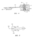
- FIGS. 3 - 6 illustrate an improved vane arm 102 in accordance with the present invention for use in an attachment system 10 used in a variable incidence vane system within a gas turbine engine.
- the vane arm 102 is used to join a vane spindle 26 and a unison ring 15.
- the vane arm 102 has an arm portion 104 with a thickness T.
- the arm portion 104 may be formed from any suitable material known in the art such as a nickel based alloy.
- a suitable nickel based alloy which may be used to form the arm portion 104 is Inconel 718.
- the vane arm 102 also has a bushing 106 connected to it.
- the bushing 106 is joined to the vane arm 102 by brazing using any suitable brazing material such as a gold based alloy or a nickel based alloy.
- the bushing 106 may also be formed from a nickel based alloy such as Inconel 718. It may also be formed from any other suitable metallic material known in the art. While it is preferred to braze the bushing 106 to the vane arm 102, if desired, the bushing 106 may be integrally formed with the vane arm 102.
- the bushing 106 has an upper portion 108 and a lower portion 110.
- the upper portion 108 has an outer diameter greater than the outer diameter of the lower portion 110.
- the bushing 106 has an interior bore 112 for receiving a pin 114 about which the bushing 106 can rotate.
- One of the features of the bushing 106 is that it has no chamfered reliefs.
- the bushing 106 has a height H which is maximized to fit within the cross section of the unison ring 15. There is a clearance between the ring 15 and the top and/or bottom of bushing 106 to eliminate the potential for contact and subsequent wear at these surfaces. The value of the clearance is intended to accommodate the kinematic travel of the bushing 106 relative to the ring 15, i.e. the bushing 106 slides up the pin 114 as the ring 15 is rotated.
- the vane arm 102 is joined to the unison ring 15 by the pin 114 which is sized to fit within the bore 112.
- the pin 114 has a first bore 124 machined in a first end and a second bore 126 machined in a second end 122.
- the joint between the unison ring 15 and the pin 114 is formed by a first swage 116 at the first end 120 of the pin 114 and a second swage 118 at the second end 122 of the pin 114.
- the vane arm/unison ring attachment described hereinabove provides a number of key advantages.
- Second, the increased bushing height provides increased bearing area which minimizes wear.
- the dual swaging of the pin 114 eliminates slop at the inner diameter of the unison ring 15, preventing wear at that mating surface.
- the vane arm 102 is also provided with an integrally formed claw feature 128 which has, as shown in FIG. 5, a tapered leading edge 130 and 132 on the first and second curved members 134 and 136 used to engage the offset slots 24 and 25 in a vane spindle 26.
- the tapered leading edges 130 and 132 taper inwardly from the leading edge of each curved member 134 and 136 towards a longitudinal axis 138 of the arm portion 104.
- the first curved member 134 has a first radius of curvature and the second curved member 136 has a second radius of curvature which is different from the first radius of curvature.
- the purpose of the different radii of curvature is to provide a fool proofing feature which prevents the arm from being installed backwards on the vane.
- the tapered claw feature 128 of the vane arm 102 provides a number of advantages. First, it reduces assembly fillet stress caused by interference fit with claw and vane spindle. Second, it reduces stress Kt caused by vane arm stem deflection and vane air loads. Third, it improves manufacturing ability to blend finish and inspect fillet area underneath the vane arm claw.
- variable vane arm/unison ring/vane attachment system which fully satisfies the objects, means, and advantages set forth hereinbefore. While the present invention has been described in the context of specific embodiments thereof, other alternatives, modifications, and variations will become apparent to those skilled in the art having read the foregoing description. Accordingly, it is intended to embrace those alternatives, modifications, and variations which fall within the broad scope of the appended claims.
Landscapes
- Engineering & Computer Science (AREA)
- Mechanical Engineering (AREA)
- General Engineering & Computer Science (AREA)
- Control Of Turbines (AREA)
- Supercharger (AREA)
- Turbine Rotor Nozzle Sealing (AREA)
- Structures Of Non-Positive Displacement Pumps (AREA)
Abstract
Description
Claims (16)
- An attachment system for use with a variable incidence vane system comprising:a vane arm (102) for connecting a unison ring (15) and a spindle (26);said vane arm (102) having an arm portion (104) and a bushing (106) connected to said arm portion (104);a pin (114) for connecting said vane arm (102) to said unison ring (15); andsaid pin (114) fitting within said bushing (106) and being joined to said unison ring by a dual swage (116,118).
- The attachment system according to claim 1, wherein said bushing (106) is connected to said arm portion (104) by brazing.
- The attachment system according to claim 1 or 2, wherein said bushing (106) has no chamfered reliefs.
- The attachment system according to any preceding claim, further comprising said vane arm (102) having means for connecting said vane arm (102) to said vane spindle (26).
- The attachment system according to claim 4, wherein said connecting means comprises a claw (128) having a tapered leading edge (130,132).
- The attachment system according to claim 5, wherein said vane spindle (26) has two offset slots and said connecting means further comprises first and second curved members (134,136) for engaging said slots.
- The attachment system according to claim 6, wherein said first curved member (134) has a first radius of curvature, said second curved member (136) has a second radius of curvature, and said first radius of curvature is different from said second radius of curvature.
- A vane arm (102) for use in an attachment system having a unison ring (15) comprising:an arm portion (104) and a bushing (106) connected to said arm portion (104);said arm portion (104) having a thickness (T); andsaid bushing (106) having a height (H) which is maximized to fit within a cross section of the unison ring (15) with a clearance between top and bottom surfaces of said bushing (106) sufficient to eliminate any potential for contact and subsequent wear of said top and bottom surfaces.
- A vane arm according to claim 8, further comprising a tapered claw structure (128) for joining said vane arm (104) to another structure.
- A vane arm according to claim 9, wherein said tapered claw structure (128) includes a tapered leading edge (130,132).
- A vane arm according to claim 10, wherein said tapered claw structure includes a first curved member (134) having a first radius of curvature, a second curved member (136) having a second radius of curvature, and said first radius of curvature being different from said second radius of curvature.
- A vane arm (102) for use in a gas turbine engine comprising an arm portion (104), a bushing (106) at a first end of said arm portion (104), and an integrally formed tapered claw feature (128) at a second end of said arm portion (104).
- A vane arm according to claim 12, further comprising said bushing (106) being brazed to said arm portion (104).
- A vane arm according to claim 12 or 13, wherein said arm portion, said tapered claw feature (128), and said bushing (106) are each formed from a nickel based alloy.
- A vane arm according to any of claims 12 to 14, wherein said claw feature (128) comprises a first curved member (134) having a tapered leading edge (130) and a second curved member (136) having a tapered leading edge (132).
- A vane arm according to claim 15, wherein said first curved member (134) has a first radius of curvature, said second curved member (136) has a second radius of curvature, and said first radius of curvature is different from said second radius of curvature.
Priority Applications (1)
| Application Number | Priority Date | Filing Date | Title |
|---|---|---|---|
| EP10011410A EP2273074B1 (en) | 2002-12-16 | 2003-12-16 | Vane arm |
Applications Claiming Priority (2)
| Application Number | Priority Date | Filing Date | Title |
|---|---|---|---|
| US10/320,031 US6984104B2 (en) | 2002-12-16 | 2002-12-16 | Variable vane arm/unison ring attachment system |
| US320031 | 2002-12-16 |
Publications (3)
| Publication Number | Publication Date |
|---|---|
| EP1431520A2 true EP1431520A2 (en) | 2004-06-23 |
| EP1431520A3 EP1431520A3 (en) | 2006-09-27 |
| EP1431520B1 EP1431520B1 (en) | 2010-10-13 |
Family
ID=32392970
Family Applications (2)
| Application Number | Title | Priority Date | Filing Date |
|---|---|---|---|
| EP10011410A Expired - Lifetime EP2273074B1 (en) | 2002-12-16 | 2003-12-16 | Vane arm |
| EP03257899A Expired - Lifetime EP1431520B1 (en) | 2002-12-16 | 2003-12-16 | Variable vane arm/unison ring attachment system |
Family Applications Before (1)
| Application Number | Title | Priority Date | Filing Date |
|---|---|---|---|
| EP10011410A Expired - Lifetime EP2273074B1 (en) | 2002-12-16 | 2003-12-16 | Vane arm |
Country Status (4)
| Country | Link |
|---|---|
| US (2) | US6984104B2 (en) |
| EP (2) | EP2273074B1 (en) |
| JP (1) | JP2004197742A (en) |
| DE (1) | DE60334520D1 (en) |
Cited By (5)
| Publication number | Priority date | Publication date | Assignee | Title |
|---|---|---|---|---|
| FR2875559A1 (en) * | 2004-09-21 | 2006-03-24 | Snecma Moteurs Sa | LEVER FOR CONTROLLING THE ANGULAR SETTING OF A STATOR BLADE IN A TURBOMACHINE |
| WO2007112910A1 (en) * | 2006-03-30 | 2007-10-11 | Borgwarner Inc. | Turbocharger |
| GB2440346A (en) * | 2006-07-25 | 2008-01-30 | Rolls Royce Plc | Bearing assembly for a variable vane |
| WO2014113010A1 (en) | 2013-01-17 | 2014-07-24 | United Technologies Corporation | Vane lever arm for a variable area vane arrangement |
| EP3865675A1 (en) * | 2020-02-13 | 2021-08-18 | Honeywell International Inc. | Variable vane system for turbomachine with linkage having tapered receiving aperture for unison ring pin |
Families Citing this family (32)
| Publication number | Priority date | Publication date | Assignee | Title |
|---|---|---|---|---|
| US7570627B2 (en) * | 2005-03-11 | 2009-08-04 | Freescale Semiconductor, Inc. | Method for sharing bandwidth using reduced duty cycle signals and media access control |
| EP1722073B1 (en) * | 2005-05-13 | 2013-01-23 | BorgWarner, Inc. | Variable geometry turbocharger unison ring |
| EP1811135A1 (en) * | 2006-01-23 | 2007-07-25 | ABB Turbo Systems AG | Variable guiding device |
| CN101743379A (en) * | 2007-04-10 | 2010-06-16 | 艾利奥特公司 | Centrifugal compressor having adjustable inlet guide vanes |
| US9133726B2 (en) * | 2007-09-17 | 2015-09-15 | United Technologies Corporation | Seal for gas turbine engine component |
| US8202043B2 (en) * | 2007-10-15 | 2012-06-19 | United Technologies Corp. | Gas turbine engines and related systems involving variable vanes |
| US8240983B2 (en) * | 2007-10-22 | 2012-08-14 | United Technologies Corp. | Gas turbine engine systems involving gear-driven variable vanes |
| US8105019B2 (en) * | 2007-12-10 | 2012-01-31 | United Technologies Corporation | 3D contoured vane endwall for variable area turbine vane arrangement |
| US8215902B2 (en) * | 2008-10-15 | 2012-07-10 | United Technologies Corporation | Scalable high pressure compressor variable vane actuation arm |
| US8414248B2 (en) * | 2008-12-30 | 2013-04-09 | Rolls-Royce Corporation | Variable geometry vane |
| SG166033A1 (en) * | 2009-05-08 | 2010-11-29 | Pratt & Whitney Services Pte Ltd | Method of electrical discharge surface repair of a variable vane trunnion |
| US8534990B2 (en) * | 2009-11-11 | 2013-09-17 | Hamilton Sundstrand Corporation | Inlet guide vane drive system with spring preload on mechanical linkage |
| US8851832B2 (en) * | 2009-12-31 | 2014-10-07 | Rolls-Royce North American Technologies, Inc. | Engine and vane actuation system for turbine engine |
| US8668444B2 (en) * | 2010-09-28 | 2014-03-11 | General Electric Company | Attachment stud for a variable vane assembly of a turbine compressor |
| US8714916B2 (en) * | 2010-09-28 | 2014-05-06 | General Electric Company | Variable vane assembly for a turbine compressor |
| US9045984B2 (en) | 2012-05-31 | 2015-06-02 | United Technologies Corporation | Stator vane mistake proofing |
| US9404384B2 (en) | 2012-09-12 | 2016-08-02 | United Technologies Corporation | Gas turbine engine synchronizing ring with multi-axis joint |
| US10030533B2 (en) * | 2012-09-21 | 2018-07-24 | United Technologies Corporation | Flanged bushing for variable vane |
| US10208618B2 (en) * | 2013-02-04 | 2019-02-19 | United Technologies Corporation | Vane arm having a claw |
| EP2971597B1 (en) | 2013-03-13 | 2021-12-29 | Raytheon Technologies Corporation | Machined vane arm of a variable vane actuation system |
| US10145264B2 (en) | 2013-07-08 | 2018-12-04 | United Technologies Corporation | Variable vane actuation system |
| US10253646B2 (en) | 2013-08-22 | 2019-04-09 | United Technologies Corporation | Vane arm assembly |
| US20160298633A1 (en) * | 2013-12-16 | 2016-10-13 | United Technologies Corporation | Shortened support for compressor variable vane |
| US10302011B2 (en) * | 2015-11-23 | 2019-05-28 | Garrett Transportation I Inc. | Exhaust gas variable turbine assembly |
| US10753224B2 (en) * | 2017-04-27 | 2020-08-25 | General Electric Company | Variable stator vane actuator overload indicating bushing |
| US10526911B2 (en) | 2017-06-22 | 2020-01-07 | United Technologies Corporation | Split synchronization ring for variable vane assembly |
| US10815818B2 (en) * | 2017-07-18 | 2020-10-27 | Raytheon Technologies Corporation | Variable-pitch vane assembly |
| DE102018202119A1 (en) | 2018-02-12 | 2019-08-14 | MTU Aero Engines AG | Lever connection of a guide vane adjustment for turbomachinery |
| US11255217B2 (en) * | 2019-09-17 | 2022-02-22 | Raytheon Technologies Corporation | Vane arm for variable vanes |
| JP7431640B2 (en) | 2020-03-31 | 2024-02-15 | 川崎重工業株式会社 | gas turbine engine unison ring |
| DE202023106055U1 (en) | 2023-10-19 | 2023-11-30 | MTU Aero Engines AG | Lever connection of a guide vane adjustment for turbomachines |
| DE202023106491U1 (en) | 2023-11-07 | 2023-12-13 | MTU Aero Engines AG | Lever connection of a guide vane adjustment for a turbomachine |
Family Cites Families (12)
| Publication number | Priority date | Publication date | Assignee | Title |
|---|---|---|---|---|
| GB837649A (en) * | 1957-11-12 | 1960-06-15 | Gen Electric | Improvements in compressor stator vane assembly |
| FR1425074A (en) * | 1965-02-22 | 1966-01-14 | Kolomensky Teplovozostroitelny | Adjustable steering device for radial turbine |
| US3502260A (en) * | 1967-09-22 | 1970-03-24 | Gen Electric | Stator vane linkage for axial flow compressors |
| US3788763A (en) * | 1972-11-01 | 1974-01-29 | Gen Motors Corp | Variable vanes |
| US3954349A (en) * | 1975-06-02 | 1976-05-04 | United Technologies Corporation | Lever connection to syncring |
| US4668165A (en) * | 1986-03-27 | 1987-05-26 | The United States Of America As Represented By The Secretary Of The Air Force | Super gripper variable vane arm |
| US4767264A (en) * | 1986-10-31 | 1988-08-30 | United Technologies Corporation | Vane lever arm construction |
| US4792277A (en) * | 1987-07-08 | 1988-12-20 | United Technologies Corporation | Split shroud compressor |
| US4979874A (en) * | 1989-06-19 | 1990-12-25 | United Technologies Corporation | Variable van drive mechanism |
| JP2000210737A (en) * | 1999-01-25 | 2000-08-02 | Yuusu Kitaura:Kk | Swaging method and swaging structure |
| US6325531B1 (en) * | 1999-12-03 | 2001-12-04 | Thomas R. Lindley | Concrete vibrator head with enhanced vibration and fluid bearing |
| US6330995B1 (en) * | 2000-02-29 | 2001-12-18 | General Electric Company | Aircraft engine mount |
-
2002
- 2002-12-16 US US10/320,031 patent/US6984104B2/en not_active Expired - Lifetime
-
2003
- 2003-12-16 EP EP10011410A patent/EP2273074B1/en not_active Expired - Lifetime
- 2003-12-16 JP JP2003417554A patent/JP2004197742A/en not_active Ceased
- 2003-12-16 EP EP03257899A patent/EP1431520B1/en not_active Expired - Lifetime
- 2003-12-16 DE DE60334520T patent/DE60334520D1/en not_active Expired - Lifetime
-
2005
- 2005-08-02 US US11/196,653 patent/US7448848B2/en not_active Expired - Fee Related
Cited By (8)
| Publication number | Priority date | Publication date | Assignee | Title |
|---|---|---|---|---|
| FR2875559A1 (en) * | 2004-09-21 | 2006-03-24 | Snecma Moteurs Sa | LEVER FOR CONTROLLING THE ANGULAR SETTING OF A STATOR BLADE IN A TURBOMACHINE |
| JP2006090319A (en) * | 2004-09-21 | 2006-04-06 | Snecma | Control lever for setting the angle of stator blades in turboshaft engines |
| US7524165B2 (en) | 2004-09-21 | 2009-04-28 | Snecma | Control lever for the angular setting of a stator blade in a turboshaft engine |
| WO2007112910A1 (en) * | 2006-03-30 | 2007-10-11 | Borgwarner Inc. | Turbocharger |
| GB2440346A (en) * | 2006-07-25 | 2008-01-30 | Rolls Royce Plc | Bearing assembly for a variable vane |
| WO2014113010A1 (en) | 2013-01-17 | 2014-07-24 | United Technologies Corporation | Vane lever arm for a variable area vane arrangement |
| EP2946117A4 (en) * | 2013-01-17 | 2016-02-24 | United Technologies Corp | DAWN LEVER ARM FOR A VARIABLE SURFACE VANE ARRANGEMENT |
| EP3865675A1 (en) * | 2020-02-13 | 2021-08-18 | Honeywell International Inc. | Variable vane system for turbomachine with linkage having tapered receiving aperture for unison ring pin |
Also Published As
| Publication number | Publication date |
|---|---|
| EP2273074B1 (en) | 2012-05-09 |
| EP1431520B1 (en) | 2010-10-13 |
| EP1431520A3 (en) | 2006-09-27 |
| JP2004197742A (en) | 2004-07-15 |
| US20050265824A1 (en) | 2005-12-01 |
| US7448848B2 (en) | 2008-11-11 |
| EP2273074A1 (en) | 2011-01-12 |
| US20040115045A1 (en) | 2004-06-17 |
| DE60334520D1 (en) | 2010-11-25 |
| US6984104B2 (en) | 2006-01-10 |
Similar Documents
| Publication | Publication Date | Title |
|---|---|---|
| US6984104B2 (en) | Variable vane arm/unison ring attachment system | |
| EP2093380B1 (en) | Single channel inner diameter shroud with lightweight inner core in a gas turbine | |
| US5553378A (en) | Method of manufacturing a piston | |
| KR100490183B1 (en) | Pipe joint and seal therefor | |
| EP0770810B1 (en) | Expansion joint | |
| EP1359297A1 (en) | Connection method for turbo charger turbine shaft | |
| EP1445537A3 (en) | Sealing assembly for the aft end of a ceramic matrix composite liner in a gas turbine engine combustor | |
| CN101173615A (en) | Variable throat exhaust turbocharger | |
| US4806040A (en) | Ceramic ball and socket joint | |
| CN101300428A (en) | Transverse shaft ball joint with sealing ring for the end of the transverse shaft sleeve | |
| EP1043529A3 (en) | High-efficiency poppet and seat assembly | |
| KR20180011451A (en) | Turbine wastegate | |
| KR20180011452A (en) | Turbine wastegate | |
| US6499387B2 (en) | Unified multi-piece piston and method of manufacture | |
| EP1329279B1 (en) | Friction welding of a reinforcing element on a thin walled member with an interlayer member interposed between | |
| US6302648B1 (en) | Steam turbine jointed stationary blade | |
| JPH01164811A (en) | Manufacture of crankshaft | |
| CN101012937A (en) | Manufacture of a combustion chamber | |
| US5592913A (en) | Exhaust valve with a tapered stem portion | |
| JP2003322135A (en) | Propeller shaft and manufacturing method thereof | |
| EP3971404B1 (en) | Exhaust duct of gas turbine engine | |
| EP3896299B1 (en) | Hinged assembly with fail-safe hinge pin | |
| US20100272572A1 (en) | Method for producing an integrally bladed rotor, and rotor | |
| JP2023537324A (en) | Wastegate actuator mechanism for turbocharger wastegate system | |
| CN215672375U (en) | Aeroengine inner casing, interstage casing and aeroengine |
Legal Events
| Date | Code | Title | Description |
|---|---|---|---|
| PUAI | Public reference made under article 153(3) epc to a published international application that has entered the european phase |
Free format text: ORIGINAL CODE: 0009012 |
|
| AK | Designated contracting states |
Kind code of ref document: A2 Designated state(s): AT BE BG CH CY CZ DE DK EE ES FI FR GB GR HU IE IT LI LU MC NL PT RO SE SI SK TR |
|
| AX | Request for extension of the european patent |
Extension state: AL LT LV MK |
|
| PUAL | Search report despatched |
Free format text: ORIGINAL CODE: 0009013 |
|
| AK | Designated contracting states |
Kind code of ref document: A3 Designated state(s): AT BE BG CH CY CZ DE DK EE ES FI FR GB GR HU IE IT LI LU MC NL PT RO SE SI SK TR |
|
| AX | Request for extension of the european patent |
Extension state: AL LT LV MK |
|
| 17P | Request for examination filed |
Effective date: 20061212 |
|
| AKX | Designation fees paid |
Designated state(s): AT BE BG |
|
| RBV | Designated contracting states (corrected) |
Designated state(s): DE FR GB |
|
| REG | Reference to a national code |
Ref country code: DE Ref legal event code: 8566 |
|
| 17Q | First examination report despatched |
Effective date: 20070802 |
|
| GRAP | Despatch of communication of intention to grant a patent |
Free format text: ORIGINAL CODE: EPIDOSNIGR1 |
|
| GRAS | Grant fee paid |
Free format text: ORIGINAL CODE: EPIDOSNIGR3 |
|
| GRAA | (expected) grant |
Free format text: ORIGINAL CODE: 0009210 |
|
| AK | Designated contracting states |
Kind code of ref document: B1 Designated state(s): DE FR GB |
|
| REG | Reference to a national code |
Ref country code: GB Ref legal event code: FG4D |
|
| REF | Corresponds to: |
Ref document number: 60334520 Country of ref document: DE Date of ref document: 20101125 Kind code of ref document: P |
|
| PLBE | No opposition filed within time limit |
Free format text: ORIGINAL CODE: 0009261 |
|
| STAA | Information on the status of an ep patent application or granted ep patent |
Free format text: STATUS: NO OPPOSITION FILED WITHIN TIME LIMIT |
|
| REG | Reference to a national code |
Ref country code: FR Ref legal event code: ST Effective date: 20110831 |
|
| 26N | No opposition filed |
Effective date: 20110714 |
|
| PG25 | Lapsed in a contracting state [announced via postgrant information from national office to epo] |
Ref country code: FR Free format text: LAPSE BECAUSE OF NON-PAYMENT OF DUE FEES Effective date: 20110103 |
|
| REG | Reference to a national code |
Ref country code: DE Ref legal event code: R097 Ref document number: 60334520 Country of ref document: DE Effective date: 20110714 |
|
| REG | Reference to a national code |
Ref country code: DE Ref legal event code: R082 Ref document number: 60334520 Country of ref document: DE Representative=s name: KLUNKER, SCHMITT-NILSON, HIRSCH, DE Ref country code: DE Ref legal event code: R081 Ref document number: 60334520 Country of ref document: DE Owner name: UNITED TECHNOLOGIES CORP. (N.D.GES.D. STAATES , US Free format text: FORMER OWNER: UNITED TECHNOLOGIES CORP., HARTFORD, CONN., US |
|
| PGFP | Annual fee paid to national office [announced via postgrant information from national office to epo] |
Ref country code: DE Payment date: 20191119 Year of fee payment: 17 |
|
| PGFP | Annual fee paid to national office [announced via postgrant information from national office to epo] |
Ref country code: GB Payment date: 20191122 Year of fee payment: 17 |
|
| REG | Reference to a national code |
Ref country code: DE Ref legal event code: R119 Ref document number: 60334520 Country of ref document: DE |
|
| GBPC | Gb: european patent ceased through non-payment of renewal fee |
Effective date: 20201216 |
|
| PG25 | Lapsed in a contracting state [announced via postgrant information from national office to epo] |
Ref country code: DE Free format text: LAPSE BECAUSE OF NON-PAYMENT OF DUE FEES Effective date: 20210701 Ref country code: GB Free format text: LAPSE BECAUSE OF NON-PAYMENT OF DUE FEES Effective date: 20201216 |