EP1431517A2 - Turbine nozzles - Google Patents
Turbine nozzles Download PDFInfo
- Publication number
- EP1431517A2 EP1431517A2 EP03257926A EP03257926A EP1431517A2 EP 1431517 A2 EP1431517 A2 EP 1431517A2 EP 03257926 A EP03257926 A EP 03257926A EP 03257926 A EP03257926 A EP 03257926A EP 1431517 A2 EP1431517 A2 EP 1431517A2
- Authority
- EP
- European Patent Office
- Prior art keywords
- turbine nozzle
- hook
- assembly
- turbine
- nozzle
- Prior art date
- Legal status (The legal status is an assumption and is not a legal conclusion. Google has not performed a legal analysis and makes no representation as to the accuracy of the status listed.)
- Withdrawn
Links
Images


Classifications
-
- F—MECHANICAL ENGINEERING; LIGHTING; HEATING; WEAPONS; BLASTING
- F01—MACHINES OR ENGINES IN GENERAL; ENGINE PLANTS IN GENERAL; STEAM ENGINES
- F01D—NON-POSITIVE DISPLACEMENT MACHINES OR ENGINES, e.g. STEAM TURBINES
- F01D9/00—Stators
- F01D9/02—Nozzles; Nozzle boxes; Stator blades; Guide conduits, e.g. individual nozzles
- F01D9/04—Nozzles; Nozzle boxes; Stator blades; Guide conduits, e.g. individual nozzles forming ring or sector
- F01D9/041—Nozzles; Nozzle boxes; Stator blades; Guide conduits, e.g. individual nozzles forming ring or sector using blades
-
- Y—GENERAL TAGGING OF NEW TECHNOLOGICAL DEVELOPMENTS; GENERAL TAGGING OF CROSS-SECTIONAL TECHNOLOGIES SPANNING OVER SEVERAL SECTIONS OF THE IPC; TECHNICAL SUBJECTS COVERED BY FORMER USPC CROSS-REFERENCE ART COLLECTIONS [XRACs] AND DIGESTS
- Y02—TECHNOLOGIES OR APPLICATIONS FOR MITIGATION OR ADAPTATION AGAINST CLIMATE CHANGE
- Y02T—CLIMATE CHANGE MITIGATION TECHNOLOGIES RELATED TO TRANSPORTATION
- Y02T50/00—Aeronautics or air transport
- Y02T50/60—Efficient propulsion technologies, e.g. for aircraft
Definitions
- This invention relates generally to gas turbine engine nozzles and more particularly, to methods and apparatus for assembling gas turbine engine nozzles.
- Gas turbine engines include combustors which ignite fuel-air mixtures which are then channeled through a turbine nozzle assembly towards a turbine.
- At least some known turbine nozzle assemblies include a plurality of nozzles arranged circumferentially and configured as doublets.
- At least some known turbine nozzles include more than two circumferentially-spaced hollow airfoil vanes coupled by integrally-formed inner and outer band platforms.
- the inner band forms a radially inner flowpath boundary and the outer band forms a radially outer flowpath boundary.
- at least some known outer bands include a forward and an aft hook assembly that are used to couple the turbine nozzle within the engine.
- Forming the turbine nozzle with a plurality of integrally-formed airfoil vanes facilitates improving durability and reducing leakage in comparison to turbine nozzles which include only one airfoil vanes.
- leakage may still occur between circumferentially-adjacent turbine nozzles, which are spaced apart by a gap or interface that facilitates engine assembly, and accommodates thermal expansion between the turbine nozzles.
- at least some known turbine nozzles include a seal assembly that is positioned radially outwardly from the aft hook assembly to facilitate minimizing leakage through the interface. Over time, thermal cycling may cause degradation of the seals. However, accessing such interface seals may be difficult due to the location of the nozzle.
- a method for assembling a turbine nozzle for a gas turbine engine comprises providing a turbine nozzle including a plurality of airfoil vanes extending between an inner band and an outer band, wherein the outer band includes at least one mounting system that extends radially outwardly therefrom and includes a rail and at least one hook, and coupling the turbine nozzle into the gas turbine engine using the mounting system such that the turbine nozzle is at least partially supported by the at least one hook.
- the method also comprises positioning a seal assembly between at least one hook and the outer band to facilitate reducing radial leakage through the turbine nozzle.
- a turbine nozzle for a gas turbine engine in another aspect of the invention, includes an outer band, an inner band, at least one airfoil vane that extends between the inner and outer bands, and a seal assembly.
- the outer band includes an inside face, an outside face, and an aft hook assembly that extends outwardly from the outside face.
- the aft hook assembly includes a rail and at least one hook extending outwardly from the rail.
- the seal assembly is positioned adjacent the outer band hook assembly and is radially inward from at least one hook.
- a gas turbine engine in a further aspect, includes at least one turbine nozzle assembly comprising a seal assembly, an outer band, an inner band, and a plurality of airfoil vanes coupled together by the outer and inner bands.
- the outer band includes a hook assembly that extends radially outwardly from the outer band, and includes a rail and at least one hook extending outwardly from the rail.
- the seal assembly is positioned radially inwardly from the at least one hook.
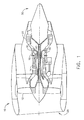
- Figure 1 is a schematic illustration of a gas turbine engine 10 including, in serial flow arrangement, a fan assembly 12, a high-pressure compressor 14, and a combustor 16.
- Engine 10 also includes a high-pressure turbine 18 and a low-pressure turbine 20.
- Engine 10 has an intake side 28 and an exhaust side 30.
- engine 10 is a CF-34 engine commercially available from General Electric Aircraft Engines, Cincinnati, Ohio.
- the highly compressed air is delivered to combustor 16 through a turbine nozzle assembly 32.
- Airflow from combustor 16 drives turbines 18 and 20, and turbine 20 drives fan assembly 12.
- Turbine 18 drives high-pressure compressor 14.
- FIG 2 is a perspective view of a turbine nozzle sector 50 that may be used with gas turbine engine 10 (shown in Figure 1).
- Figure 3 is a side perspective view of turbine nozzle sector 50.
- Figure 4 is a partial cross-sectional view of engine 10 including a partial view of turbine nozzle sector 50.
- Nozzle 50 includes a plurality of circumferentially-spaced airfoil vanes 52 coupled together by an arcuate radially outer band or platform 54 and an arcuate radially inner band or platform 56. More specifically, in the exemplary embodiment, each band 54 and 56 is integrally-formed with airfoil vanes 52, and nozzle sector 50 includes four airfoil vanes 52. In one embodiment, each arcuate nozzle sector 50 is known as a four vane segment.
- Inner band 56 includes an aft flange 60 that extends radially inwardly therefrom. More specifically, flange 60 extends radially inwardly from band 56 with respect to a radially inner surface 62 of band 56. Inner band 56 also includes a forward flange 64 that extends radially inwardly therefrom.
- Forward flange 64 is positioned between an upstream edge 66 of inner band 56 and aft flange 60, and extends radially inwardly from band 56.
- Outer band 54 includes a cantilever mounting system 70 that includes a forward retainer 72, a mid hook assembly 74, and an aft hook assembly 76.
- Cantilever mounting system 70 facilitates supporting turbine nozzle 50 within engine 10 from a surrounding annular engine casing (not shown).
- Forward retainer 72 extends radially outwardly from an outer surface 80 of outer band 54 and defines a channel 82 that extends continuously in a circumferential direction across a leading edge 84 of outer band 54.
- Outer band 54 also includes a trailing edge 86 that is coupled to leading edge 84 by a pair of oppositely-disposed sector ends 87.
- Mid hook assembly 74 is positioned aft of forward retainer 72 and in the exemplary embodiment, includes a plurality of circumferentially-spaced and circumferentially-aligned hooks 90 that each extend upstream from a forward rail 92.
- Forward rail 92 extends radially outwardly from outer band outer surface 80.
- Hook assembly 74 extends in a circumferential direction across outer band outer surface 80 between circumferential ends 87.
- Aft hook assembly 76 is positioned aft of mid hook assembly 74, and as such is between nozzle trailing edge 86 and mid hook assembly 74.
- Hook assembly 76 includes an aft rail 94 and a plurality of hooks 96.
- Rail 94 extends radially outwardly from outer band outer surface 80 in a circumferential direction across outer band outer surface 80 and between circumferential ends 87.
- Hooks 96 do not extend continuously between circumferential ends 87, but rather hooks 96 are scalloped such that adjacent hooks 96 are spaced a distance 102 apart. Accordingly, a scalloped recessed area 104 is defined between each set of adjacent hooks 96. Specifically, each recessed area 104 is radially aligned and radially outwardly from a respective airfoil vane 52. As such, each hook 96 is radially aligned between adjacent vanes 52.
- nozzle 50 includes four scalloped recessed areas 104.
- Airfoil vanes 52 are substantially similar and each includes a first sidewall 110 and a second sidewall 112.
- First sidewall 110 is convex and defines a suction side of each airfoil 52
- second sidewall 112 is concave and defines a pressure side of each airfoil vane 52.
- Sidewalls 110 and 112 are joined at a leading edge 114 and at an axially-spaced trailing edge 116 of each airfoil vane 52, such that a cavity 118 is defined therebetween.
- Scalloped recessed areas 104 facilitate access to cavities defined within vanes 52. In one embodiment, inserts (not shown) are inserted within each cavity 118, and recessed areas 104 facilitate their installation and removal.
- each airfoil trailing edge 116 is spaced chordwise and downstream from each respective airfoil leading edge 114.
- First and second sidewalls 110 and 112, respectively, also extend longitudinally, or radially outwardly, in span from radially inner band 56 to radially outer band 54.
- each arcuate nozzle portion 50 includes a pair of circumferentially inner airfoil vanes 120 and 122, and a pair of circumferentially outer airfoil vanes 124 and 126. Vanes 120, 122, 124, and 126 are also oriented substantially parallel to each other. Separation distance 102 and an orientation of vanes 52 are each variably selected to facilitate creating a highly divergent flowpath through nozzle 50, and to facilitate optimizing aerodynamic accelerating flow through nozzle sector 50.
- Engine 10 includes a rotor assembly 140, such as low pressure turbine 20, that includes at least one row of rotor blades 142 that is downstream from turbine nozzles 50.
- Rotor assembly 140 is surrounded by a rotor shroud 144 that extends circumferentially around rotor assembly 140 and turbine nozzles 50.
- Cantilever mounting system 70 couples each turbine nozzle 50 to rotor shroud 144 through a hanger 148 that is supported by and coupled to shroud 144. More specifically, each hook 96 is slidably coupled within a radially outer channel 150 defined within hanger 148.
- Hanger 148 also includes a radially inner channel 152 defined therein. Radially inner channel 152 is radially inward from radially outer channel 150 and each channel 150 and 152 is defined inwardly from a downstream side 154 of hanger 148. Accordingly, each channel 150 and 152 is adjacent aft hook assembly 76. Furthermore, when aft hook assembly 76 is coupled to hanger 148, a cavity 160 is defined between hanger 148, aft hook assembly 76, and outer band 54.
- seal assembly 170 is positioned radially inwardly from hooks 96 and extends within hanger radially inner channel 152. More specifically, seal assembly 170 includes a seal member 172 that extends in sealing contact between hanger 148 and aft hook assembly rail 94. In one embodiment, seal member 172 extends substantially circumferentially through engine 10 to facilitate minimizing radial leakage past aft hook assembly 76, as described in more detail below. In an alternative embodiment, seal members 170 are segmented spline seals. In the exemplary embodiment, seal member 172 is a w-seal.
- cooling air is extracted from a high pressure source, such as combustor 16, and directed at a high pressure into cavity 160. More specifically, high pressure cooling air circulates through cavity 160 and facilitates cooling outer band 54 and turbine nozzle vanes 52. Combustion gases flowing through turbine nozzle 50 create an area of low pressure conducive for leakage of high pressure cooling air between hanger 148 and aft hook assembly 76. However, the relative high pressure of the cooling air causes seal member 172 to expand to facilitate preventing leakage between hanger 148 and aft hook assembly 76.
- seal assembly 170 facilitates enhanced sealing in comparison to other known turbine nozzles.
- the combination of the enhanced sealing and the position of seal member 170 with respect to the flow path, enables aft hook assembly rail 94 to be fabricated with a radial height 190 that is shorter than other known aft rails.
- aft hook assembly 76 is also scalloped, an overall weight of turbine nozzle 50 is reduced in comparison to other known turbine nozzles that do not include recessed areas 104. As a result, mechanical stresses and thermal stresses induced within nozzle 50 are facilitated to be reduced.
- the above-described turbine nozzle includes a scalloped aft hook assembly that extends from the aft rail.
- the hook assembly includes a plurality of recessed areas that are circumferentially spaced across the outer band. The recessed areas not only reduce an overall weight of the turbine nozzle assembly, but also facilitate reducing thermal stresses induced to the turbine nozzle.
- the turbine nozzle includes a seal assembly that is positioned radially inwardly from the aft hook assembly. Accordingly, the seal assembly is closer to the flowpath than other known seal assemblies, which facilitates enhanced sealing in comparison to other known seal assemblies, and also permits weight and stress reduction measures, including scalloping and/or removing portions of the radial flange above the sealing surface. As a result, the durability and useful life of the turbine nozzle are facilitated to be increased by the combination of the scalloped hook assembly and the seal assembly.
- turbine nozzles Exemplary embodiments of turbine nozzles are described above in detail.
- the nozzles are not limited to the specific embodiments described herein, but rather, components of each turbine nozzle may be utilized independently and separately from other components described herein.
Landscapes
- Engineering & Computer Science (AREA)
- Mechanical Engineering (AREA)
- General Engineering & Computer Science (AREA)
- Turbine Rotor Nozzle Sealing (AREA)
- Gasket Seals (AREA)
Abstract
Description
Claims (8)
- A turbine nozzle (50) for a gas turbine engine (10), said nozzle (50) comprising:an outer band (54) comprising an inside face (62), an outside face (80), and an aft hook assembly (76) extending outwardly from said outside face (80), said aft hook assembly comprising a rail (94) and at least one hook (96) extending outwardly from said rail;an inner band (56);at least one airfoil vane (120), (122), (124), (126) extending between said outer band 54 and said inner band (56); anda seal assembly (170) positioned adjacent said outer band hook assembly (74, 76) and radially inward from said at least one hook.
- A turbine nozzle (50) in accordance with Claim 1 wherein said seal assembly (170) is between said outer band outside face (80) and said aft hook assembly (76) at least one hook (96).
- A turbine nozzle (50) in accordance with Claim 1 wherein said seal assembly (170) comprises a w-seal.
- A turbine nozzle (50) in accordance with Claim 1 wherein said outer band (54) is arcuate and further comprises an upstream side (66), a downstream side (154), and a pair of circumferential outer sides (87) extending between said upstream and downstream sides (66), (154), said aft hook assembly rail (94) extending across said outer band outer face (80) between said circumferential outer sides, said at least one hook (90) comprising at least one scalloped recessed area (104).
- A turbine nozzle (50) in accordance with Claim 4 wherein said at least one scalloped recessed area (104) is substantially radially aligned with a downstream side (154) of said
- A turbine nozzle (50) in accordance with Claim 4 wherein said at least one scalloped recessed area (104) facilitates reducing thermal stresses induced to said turbine nozzle.
- A turbine nozzle (50) in accordance with Claim 4 wherein said at least one scalloped recessed area (104) facilitates radial access to said turbine nozzle airfoil vane (120), (122), (124), (126).
- A turbine nozzle (50) in accordance with Claim 4 wherein said seal assembly (170) is configured to reduce radial fluid leakage past said turbine nozzle 50.
Applications Claiming Priority (2)
| Application Number | Priority Date | Filing Date | Title |
|---|---|---|---|
| US324849 | 1989-03-17 | ||
| US10/324,849 US6893217B2 (en) | 2002-12-20 | 2002-12-20 | Methods and apparatus for assembling gas turbine nozzles |
Publications (2)
| Publication Number | Publication Date |
|---|---|
| EP1431517A2 true EP1431517A2 (en) | 2004-06-23 |
| EP1431517A3 EP1431517A3 (en) | 2005-10-12 |
Family
ID=32393080
Family Applications (1)
| Application Number | Title | Priority Date | Filing Date |
|---|---|---|---|
| EP03257926A Withdrawn EP1431517A3 (en) | 2002-12-20 | 2003-12-16 | Turbine nozzles |
Country Status (4)
| Country | Link |
|---|---|
| US (1) | US6893217B2 (en) |
| EP (1) | EP1431517A3 (en) |
| JP (1) | JP4515086B2 (en) |
| CN (1) | CN100339562C (en) |
Cited By (7)
| Publication number | Priority date | Publication date | Assignee | Title |
|---|---|---|---|---|
| EP2071129A1 (en) * | 2007-12-14 | 2009-06-17 | Snecma | Sectorised distributor for a turbomachine |
| EP1688586B1 (en) * | 2003-10-31 | 2013-07-03 | Kabushiki Kaisha Toshiba | Turbine cascade structure |
| WO2013171407A1 (en) * | 2012-05-16 | 2013-11-21 | Snecma | Turbomachine distributor and production method |
| EP1944473A3 (en) * | 2007-01-05 | 2014-12-17 | Rolls-Royce plc | Nozzle guide vane arrangement |
| EP2971571A4 (en) * | 2013-03-13 | 2016-11-16 | United Technologies Corp | STATOR SEGMENT |
| EP3176388A1 (en) * | 2015-12-04 | 2017-06-07 | MTU Aero Engines GmbH | Guide blade segment with radial securing |
| FR3072718A1 (en) * | 2017-10-20 | 2019-04-26 | Safran Aircraft Engines | DISTRIBUTOR AREA FOR TURBOMACHINE COMPRISING A FASTENING REBORD |
Families Citing this family (22)
| Publication number | Priority date | Publication date | Assignee | Title |
|---|---|---|---|---|
| US7762761B2 (en) * | 2005-11-30 | 2010-07-27 | General Electric Company | Methods and apparatus for assembling turbine nozzles |
| US7360988B2 (en) * | 2005-12-08 | 2008-04-22 | General Electric Company | Methods and apparatus for assembling turbine engines |
| US20070134087A1 (en) * | 2005-12-08 | 2007-06-14 | General Electric Company | Methods and apparatus for assembling turbine engines |
| FR2899275A1 (en) * | 2006-03-30 | 2007-10-05 | Snecma Sa | Ring sector fixing device for e.g. turboprop of aircraft, has cylindrical rims engaged on casing rail, where each cylindrical rim comprises annular collar axially clamped on casing rail using annular locking unit |
| US7419352B2 (en) * | 2006-10-03 | 2008-09-02 | General Electric Company | Methods and apparatus for assembling turbine engines |
| US7771164B2 (en) * | 2006-12-18 | 2010-08-10 | General Electric Company | Method and system for assembling a turbine engine |
| FR2923525B1 (en) * | 2007-11-13 | 2009-12-18 | Snecma | SEALING A ROTOR RING IN A TURBINE FLOOR |
| FR2925572B1 (en) * | 2007-12-24 | 2010-02-12 | Snecma Services | METHOD FOR CHOOSING A SECTOR ARRANGEMENT FOR A TURBOMACHINE DISPENSER |
| US8449249B2 (en) * | 2010-04-09 | 2013-05-28 | Williams International Co., L.L.C. | Turbine nozzle apparatus and associated method of manufacture |
| US8668445B2 (en) * | 2010-10-15 | 2014-03-11 | General Electric Company | Variable turbine nozzle system |
| US8651497B2 (en) | 2011-06-17 | 2014-02-18 | United Technologies Corporation | Winged W-seal |
| US9851008B2 (en) * | 2012-06-04 | 2017-12-26 | United Technologies Corporation | Seal land for static structure of a gas turbine engine |
| US10598036B2 (en) | 2013-03-13 | 2020-03-24 | United Technologies Corporation | Assembly for sealing a gap between components of a turbine engine |
| WO2014152209A1 (en) * | 2013-03-14 | 2014-09-25 | United Technologies Corporation | Assembly for sealing a gap between components of a turbine engine |
| US10822980B2 (en) * | 2013-04-11 | 2020-11-03 | Raytheon Technologies Corporation | Gas turbine engine stress isolation scallop |
| US10138746B2 (en) | 2013-06-14 | 2018-11-27 | United Technologies Corporation | Gas turbine engine flow control device |
| JP5717904B1 (en) * | 2014-08-04 | 2015-05-13 | 三菱日立パワーシステムズ株式会社 | Stator blade, gas turbine, split ring, stator blade remodeling method, and split ring remodeling method |
| EP3088691B1 (en) * | 2015-04-27 | 2019-06-19 | Ansaldo Energia Switzerland AG | Gas turbine disassembly method |
| JP7284737B2 (en) * | 2020-08-06 | 2023-05-31 | 三菱重工業株式会社 | gas turbine vane |
| CN112324521A (en) * | 2020-11-03 | 2021-02-05 | 中国航发沈阳发动机研究所 | Tandem stator structure |
| FR3116861B1 (en) * | 2020-11-27 | 2022-10-21 | Safran Aircraft Engines | DEVICE AND METHOD FOR CONTROLLING THE SECTORS FOR THE ASSEMBLY OF DISTRIBUTORS OF A TURBINE |
| CN115142907B (en) * | 2022-09-02 | 2022-11-22 | 中国航发沈阳发动机研究所 | An integrated structure of an aeroengine guide vane inner ring |
Family Cites Families (37)
| Publication number | Priority date | Publication date | Assignee | Title |
|---|---|---|---|---|
| US3842595A (en) * | 1972-12-26 | 1974-10-22 | Gen Electric | Modular gas turbine engine |
| US4126405A (en) | 1976-12-16 | 1978-11-21 | General Electric Company | Turbine nozzle |
| US4314792A (en) * | 1978-12-20 | 1982-02-09 | United Technologies Corporation | Turbine seal and vane damper |
| US4297077A (en) | 1979-07-09 | 1981-10-27 | Westinghouse Electric Corp. | Cooled turbine vane |
| US4425078A (en) * | 1980-07-18 | 1984-01-10 | United Technologies Corporation | Axial flexible radially stiff retaining ring for sealing in a gas turbine engine |
| US4531289A (en) | 1983-01-28 | 1985-07-30 | F. M. Brick Industries, Inc. | High-power rescue tool |
| US4842249A (en) | 1983-09-16 | 1989-06-27 | Weigand George R | Spreader type rescue tool |
| US4522054A (en) | 1983-09-26 | 1985-06-11 | Power Pry Corporation | Emergency rescue apparatus |
| US4687413A (en) * | 1985-07-31 | 1987-08-18 | United Technologies Corporation | Gas turbine engine assembly |
| US4732029A (en) | 1985-09-17 | 1988-03-22 | Bertino Joseph E | Accident rescue tool |
| US4869465A (en) | 1986-06-24 | 1989-09-26 | Mordechai Yirmiyahu | Power-operated spreader tool |
| US5092735A (en) * | 1990-07-02 | 1992-03-03 | The United States Of America As Represented By The Secretary Of The Air Force | Blade outer air seal cooling system |
| US5149250A (en) * | 1991-02-28 | 1992-09-22 | General Electric Company | Gas turbine vane assembly seal and support system |
| US5289711A (en) | 1991-05-15 | 1994-03-01 | Spiegel Leo J | Apparatus for spreading steel structures |
| CA2070511C (en) * | 1991-07-22 | 2001-08-21 | Steven Milo Toborg | Turbine nozzle support |
| US5243761A (en) | 1992-03-18 | 1993-09-14 | Hale Fire Pump Company | Portable rescue tool |
| US5249920A (en) | 1992-07-09 | 1993-10-05 | General Electric Company | Turbine nozzle seal arrangement |
| US5372476A (en) | 1993-06-18 | 1994-12-13 | General Electric Company | Turbine nozzle support assembly |
| US5358379A (en) * | 1993-10-27 | 1994-10-25 | Westinghouse Electric Corporation | Gas turbine vane |
| US5425260A (en) | 1994-01-27 | 1995-06-20 | Gehron; Michael A. | Accident rescue tool |
| US5662160A (en) | 1995-10-12 | 1997-09-02 | General Electric Co. | Turbine nozzle and related casting method for optimal fillet wall thickness control |
| US5620300A (en) | 1995-11-16 | 1997-04-15 | General Electric Co. | Method of constructing a turbine nozzle to prevent structurally induced excitation forces |
| US5669757A (en) | 1995-11-30 | 1997-09-23 | General Electric Company | Turbine nozzle retainer assembly |
| US5732932A (en) | 1996-03-27 | 1998-03-31 | American Rescue Technology Incorporated | Hydraulic ram attachment for a rescue tool |
| US5953822A (en) | 1996-12-24 | 1999-09-21 | Rescue Technology, Inc. | Rescue tool |
| US5875554A (en) | 1996-12-24 | 1999-03-02 | Rescue Technology, Inc. | Rescue tool |
| US5810333A (en) | 1997-02-06 | 1998-09-22 | Curtiss Wright Flight Systems Inc. | Ram device |
| US6076835A (en) * | 1997-05-21 | 2000-06-20 | Allison Advanced Development Company | Interstage van seal apparatus |
| US6193465B1 (en) | 1998-09-28 | 2001-02-27 | General Electric Company | Trapped insert turbine airfoil |
| DE19848103A1 (en) * | 1998-10-19 | 2000-04-20 | Asea Brown Boveri | Sealing arrangement |
| US6099245A (en) | 1998-10-30 | 2000-08-08 | General Electric Company | Tandem airfoils |
| US6311537B1 (en) | 1998-10-30 | 2001-11-06 | Orlando C. Vigil | Blade tip for a rescue tool |
| US6120242A (en) * | 1998-11-13 | 2000-09-19 | General Electric Company | Blade containing turbine shroud |
| US6227800B1 (en) * | 1998-11-24 | 2001-05-08 | General Electric Company | Bay cooled turbine casing |
| US6164656A (en) | 1999-01-29 | 2000-12-26 | General Electric Company | Turbine nozzle interface seal and methods |
| US6272900B1 (en) | 1999-04-21 | 2001-08-14 | Matthew Kobel | Extension ram tip |
| FR2803871B1 (en) * | 2000-01-13 | 2002-06-07 | Snecma Moteurs | DIAMETER ADJUSTMENT ARRANGEMENT OF A GAS TURBINE STATOR |
-
2002
- 2002-12-20 US US10/324,849 patent/US6893217B2/en not_active Expired - Lifetime
-
2003
- 2003-12-16 EP EP03257926A patent/EP1431517A3/en not_active Withdrawn
- 2003-12-19 JP JP2003421872A patent/JP4515086B2/en not_active Expired - Fee Related
- 2003-12-22 CN CNB2003101131026A patent/CN100339562C/en not_active Expired - Lifetime
Cited By (15)
| Publication number | Priority date | Publication date | Assignee | Title |
|---|---|---|---|---|
| EP1688586B1 (en) * | 2003-10-31 | 2013-07-03 | Kabushiki Kaisha Toshiba | Turbine cascade structure |
| EP1944473A3 (en) * | 2007-01-05 | 2014-12-17 | Rolls-Royce plc | Nozzle guide vane arrangement |
| FR2925107A1 (en) * | 2007-12-14 | 2009-06-19 | Snecma Sa | SECTORIZED DISPENSER FOR A TURBOMACHINE |
| EP2071129A1 (en) * | 2007-12-14 | 2009-06-17 | Snecma | Sectorised distributor for a turbomachine |
| US8147189B2 (en) | 2007-12-14 | 2012-04-03 | Snecma | Sectorized nozzle for a turbomachine |
| GB2516397B (en) * | 2012-05-16 | 2018-11-28 | Snecma | Turbomachine distributor and production method |
| WO2013171407A1 (en) * | 2012-05-16 | 2013-11-21 | Snecma | Turbomachine distributor and production method |
| FR2990719A1 (en) * | 2012-05-16 | 2013-11-22 | Snecma | TURBOMACHINE DISPENSER AND METHOD OF MANUFACTURE |
| GB2516397A (en) * | 2012-05-16 | 2015-01-21 | Snecma | Turbomachine distributor and production method |
| EP2971571A4 (en) * | 2013-03-13 | 2016-11-16 | United Technologies Corp | STATOR SEGMENT |
| US9988915B2 (en) | 2013-03-13 | 2018-06-05 | United Technologies Corporation | Stator segment |
| DE102015224378A1 (en) * | 2015-12-04 | 2017-06-08 | MTU Aero Engines AG | Guide vane segment with radial lock |
| EP3176388A1 (en) * | 2015-12-04 | 2017-06-07 | MTU Aero Engines GmbH | Guide blade segment with radial securing |
| US10370989B2 (en) | 2015-12-04 | 2019-08-06 | MTU Aero Engines AG | Guide vane segment with radical securing elements |
| FR3072718A1 (en) * | 2017-10-20 | 2019-04-26 | Safran Aircraft Engines | DISTRIBUTOR AREA FOR TURBOMACHINE COMPRISING A FASTENING REBORD |
Also Published As
| Publication number | Publication date |
|---|---|
| EP1431517A3 (en) | 2005-10-12 |
| US6893217B2 (en) | 2005-05-17 |
| CN100339562C (en) | 2007-09-26 |
| CN1512039A (en) | 2004-07-14 |
| JP4515086B2 (en) | 2010-07-28 |
| US20040120814A1 (en) | 2004-06-24 |
| JP2004204844A (en) | 2004-07-22 |
Similar Documents
| Publication | Publication Date | Title |
|---|---|---|
| US6893217B2 (en) | Methods and apparatus for assembling gas turbine nozzles | |
| US7762761B2 (en) | Methods and apparatus for assembling turbine nozzles | |
| CN109838281B (en) | Shrouds for Gas Turbine Engines | |
| EP1431513B1 (en) | Gas turbine nozzle and gas turbine engine comprising a gas turbine nozzle | |
| US9845691B2 (en) | Turbine nozzle outer band and airfoil cooling apparatus | |
| US9500095B2 (en) | Turbine shroud segment sealing | |
| US20090238683A1 (en) | Vane with integral inner air seal | |
| EP1795707B1 (en) | Leading edge fillet for gas turbine engine nozzle | |
| US8172504B2 (en) | Hybrid impingement cooled airfoil | |
| EP2264283A2 (en) | A cooled component for a gas turbine engine | |
| US7360988B2 (en) | Methods and apparatus for assembling turbine engines | |
| EP3415719A1 (en) | Turbomachine blade coolings structure | |
| EP2096265A2 (en) | Turbine nozzle with integral impingement blanket | |
| CN107461225B (en) | Nozzle cooling system for gas turbine engine | |
| EP1795712A2 (en) | Methods and apparatus for assembling turbine engines | |
| KR20190000306A (en) | Turbomachine rotor blade | |
| CA2596040C (en) | Methods and apparatus for assembling turbine engines |
Legal Events
| Date | Code | Title | Description |
|---|---|---|---|
| PUAI | Public reference made under article 153(3) epc to a published international application that has entered the european phase |
Free format text: ORIGINAL CODE: 0009012 |
|
| AK | Designated contracting states |
Kind code of ref document: A2 Designated state(s): AT BE BG CH CY CZ DE DK EE ES FI FR GB GR HU IE IT LI LU MC NL PT RO SE SI SK TR |
|
| AX | Request for extension of the european patent |
Extension state: AL LT LV MK |
|
| PUAL | Search report despatched |
Free format text: ORIGINAL CODE: 0009013 |
|
| RIC1 | Information provided on ipc code assigned before grant |
Ipc: 7F 01D 11/00 B Ipc: 7F 01D 25/24 B Ipc: 7F 01D 9/04 A |
|
| AK | Designated contracting states |
Kind code of ref document: A3 Designated state(s): AT BE BG CH CY CZ DE DK EE ES FI FR GB GR HU IE IT LI LU MC NL PT RO SE SI SK TR |
|
| AX | Request for extension of the european patent |
Extension state: AL LT LV MK |
|
| 17P | Request for examination filed |
Effective date: 20060412 |
|
| AKX | Designation fees paid |
Designated state(s): DE FR GB |
|
| 17Q | First examination report despatched |
Effective date: 20060801 |
|
| STAA | Information on the status of an ep patent application or granted ep patent |
Free format text: STATUS: THE APPLICATION IS DEEMED TO BE WITHDRAWN |
|
| 18D | Application deemed to be withdrawn |
Effective date: 20150701 |