EP1431514B1 - Venturi outlet turbine airfoil - Google Patents
Venturi outlet turbine airfoil Download PDFInfo
- Publication number
- EP1431514B1 EP1431514B1 EP03257920A EP03257920A EP1431514B1 EP 1431514 B1 EP1431514 B1 EP 1431514B1 EP 03257920 A EP03257920 A EP 03257920A EP 03257920 A EP03257920 A EP 03257920A EP 1431514 B1 EP1431514 B1 EP 1431514B1
- Authority
- EP
- European Patent Office
- Prior art keywords
- airfoil
- venturi
- slot
- slots
- venturi slots
- Prior art date
- Legal status (The legal status is an assumption and is not a legal conclusion. Google has not performed a legal analysis and makes no representation as to the accuracy of the status listed.)
- Expired - Fee Related
Links
Images


Classifications
-
- F—MECHANICAL ENGINEERING; LIGHTING; HEATING; WEAPONS; BLASTING
- F01—MACHINES OR ENGINES IN GENERAL; ENGINE PLANTS IN GENERAL; STEAM ENGINES
- F01D—NON-POSITIVE DISPLACEMENT MACHINES OR ENGINES, e.g. STEAM TURBINES
- F01D5/00—Blades; Blade-carrying members; Heating, heat-insulating, cooling or antivibration means on the blades or the members
- F01D5/12—Blades
- F01D5/14—Form or construction
- F01D5/18—Hollow blades, i.e. blades with cooling or heating channels or cavities; Heating, heat-insulating or cooling means on blades
- F01D5/187—Convection cooling
-
- F—MECHANICAL ENGINEERING; LIGHTING; HEATING; WEAPONS; BLASTING
- F05—INDEXING SCHEMES RELATING TO ENGINES OR PUMPS IN VARIOUS SUBCLASSES OF CLASSES F01-F04
- F05D—INDEXING SCHEME FOR ASPECTS RELATING TO NON-POSITIVE-DISPLACEMENT MACHINES OR ENGINES, GAS-TURBINES OR JET-PROPULSION PLANTS
- F05D2230/00—Manufacture
- F05D2230/20—Manufacture essentially without removing material
- F05D2230/21—Manufacture essentially without removing material by casting
-
- F—MECHANICAL ENGINEERING; LIGHTING; HEATING; WEAPONS; BLASTING
- F05—INDEXING SCHEMES RELATING TO ENGINES OR PUMPS IN VARIOUS SUBCLASSES OF CLASSES F01-F04
- F05D—INDEXING SCHEME FOR ASPECTS RELATING TO NON-POSITIVE-DISPLACEMENT MACHINES OR ENGINES, GAS-TURBINES OR JET-PROPULSION PLANTS
- F05D2250/00—Geometry
- F05D2250/30—Arrangement of components
- F05D2250/32—Arrangement of components according to their shape
- F05D2250/323—Arrangement of components according to their shape convergent
-
- F—MECHANICAL ENGINEERING; LIGHTING; HEATING; WEAPONS; BLASTING
- F05—INDEXING SCHEMES RELATING TO ENGINES OR PUMPS IN VARIOUS SUBCLASSES OF CLASSES F01-F04
- F05D—INDEXING SCHEME FOR ASPECTS RELATING TO NON-POSITIVE-DISPLACEMENT MACHINES OR ENGINES, GAS-TURBINES OR JET-PROPULSION PLANTS
- F05D2250/00—Geometry
- F05D2250/30—Arrangement of components
- F05D2250/32—Arrangement of components according to their shape
- F05D2250/324—Arrangement of components according to their shape divergent
-
- F—MECHANICAL ENGINEERING; LIGHTING; HEATING; WEAPONS; BLASTING
- F05—INDEXING SCHEMES RELATING TO ENGINES OR PUMPS IN VARIOUS SUBCLASSES OF CLASSES F01-F04
- F05D—INDEXING SCHEME FOR ASPECTS RELATING TO NON-POSITIVE-DISPLACEMENT MACHINES OR ENGINES, GAS-TURBINES OR JET-PROPULSION PLANTS
- F05D2250/00—Geometry
- F05D2250/50—Inlet or outlet
- F05D2250/52—Outlet
-
- F—MECHANICAL ENGINEERING; LIGHTING; HEATING; WEAPONS; BLASTING
- F05—INDEXING SCHEMES RELATING TO ENGINES OR PUMPS IN VARIOUS SUBCLASSES OF CLASSES F01-F04
- F05D—INDEXING SCHEME FOR ASPECTS RELATING TO NON-POSITIVE-DISPLACEMENT MACHINES OR ENGINES, GAS-TURBINES OR JET-PROPULSION PLANTS
- F05D2260/00—Function
- F05D2260/20—Heat transfer, e.g. cooling
- F05D2260/221—Improvement of heat transfer
-
- Y—GENERAL TAGGING OF NEW TECHNOLOGICAL DEVELOPMENTS; GENERAL TAGGING OF CROSS-SECTIONAL TECHNOLOGIES SPANNING OVER SEVERAL SECTIONS OF THE IPC; TECHNICAL SUBJECTS COVERED BY FORMER USPC CROSS-REFERENCE ART COLLECTIONS [XRACs] AND DIGESTS
- Y02—TECHNOLOGIES OR APPLICATIONS FOR MITIGATION OR ADAPTATION AGAINST CLIMATE CHANGE
- Y02T—CLIMATE CHANGE MITIGATION TECHNOLOGIES RELATED TO TRANSPORTATION
- Y02T50/00—Aeronautics or air transport
- Y02T50/60—Efficient propulsion technologies, e.g. for aircraft
Definitions
- the present invention relates generally to gas turbine engines, and, more specifically, to turbines therein.
- air is pressurized in a compressor and mixed with fuel in a combustor for generating hot combustion gases which flow downstream through turbines that extract energy therefrom.
- High and low pressure turbines extract energy in turn for correspondingly powering the compressor and providing useful work, such as powering an upstream fan in an exemplary turbofan engine for powering an aircraft in flight.
- Rotary turbine blades and stationary turbine nozzle vanes have corresponding airfoil profiles precisely configured for maximizing efficiency of energy extraction from the combustion gases. These components are heated by the hot combustion gases during operation, and therefore require suitable cooling for ensuring a long useful life.
- Turbine airfoil cooling is conventionally effected by forming various cooling circuits therein which are fed from air bled from the compressor used as a coolant for protecting the airfoils during operation. Diverting compressed air from the combustor correspondingly decreases efficiency of the engine, and therefore it is desired to minimize the use of parasitic cooling air while suitably protecting the hot turbine components.
- Turbine airfoil discharge holes are found at various locations between the leading and trailing edges of the airfoil and from root to tip thereof, and have various sizes and configurations selected to improve performance in the complex three-dimensional combustion gas flow field surrounding the airfoils. And, the airfoils are subject to complex stress distribution at the different parts thereof due to the complex temperature distribution.
- the cooling configurations of the turbine airfoils are also dependent on the physical size of the airfoils from large to small, with the smaller airfoils having additional problems for efficient cooling thereof due to the practical lower limit in size of cooling features which may be introduced therein.
- the trailing edge of a turbine airfoil is relatively thin in view of the typical aerodynamic profile of the airfoil which has a maximum thickness near the leading edge, with the two sidewalls converging to the sharp trailing edge.
- the internal cooling circuit of the airfoil must correspondingly decrease in size to fit between the converging sidewalls of the airfoil, and typically must terminate before reaching the trailing edge for small airfoils, or airfoils having similarly thin trailing edges.
- the internal cooling circuit In order to adequately cool the airfoil trailing edge, the internal cooling circuit typically discharges into a row of trailing edge holes formed through the pressure size of the airfoil just upstream of the trailing edge.
- the discharge coolant provides a protective film of cooling air which travels downstream over the trailing edge for protection thereof from the hot combustion gases.
- the minimum-size typical outlet holes may discharge more cooling air than required due to their relatively large size, and therefore decrease overall engine efficiency.
- Turbine blades and vanes are typically cast using a ceramic core for the internal cooling features thereof in the conventional lost wax casting process.
- Ceramic core yield is a significant factor in manufacturing turbine airfoils, and small cooling features embodied in the core are typically associated with lower yield.
- the trailing edge discharge holes are particularly problematic in manufacturing turbine airfoils since they correspondingly have small features which have practical lower-size limits in the casting of small turbine airfoils.
- the trailing edge holes have a finite axial or chordal length and are typically arranged in a radial row disposed in flow communication with a common radial flow passage inside the airfoil.
- the corresponding ceramic core has a common ceramic leg with a row of cantilevered ceramic fingers representing the trailing edge holes after casting.
- the ceramic core may be sufficiently strong for obtaining a sufficient yield for economically casting the airfoils.
- the ceramic fingers would become unacceptably small and fragile leading to an unacceptable yield rendering their use in manufacture impractical.
- the small airfoil may be cast with a corresponding ceramic core omitting the ceramic fingers and the trailing edge holes for casting the airfoil.
- the so-cast airfoil then undergoes a subsequent manufacturing operation for drilling the trailing edge holes, typically using electrical discharge machining (EDM) or electrostream (ES) machining for achieving the small size and tolerances required for the small trailing edge holes.
- EDM electrical discharge machining
- ES electrostream
- a turbine airfoil includes sidewalls extending between leading and trailing edges, with an internal cooling circuit therein.
- a row of venturi slots commences inside the airfoil at the cooling circuit and terminates near the trailing edge.
- Each of the venturi slots includes an inlet, converging portion, throat, diverging portion, and outlet in serial flow communication from the cooling circuit.
- the converging portion is comparable in chordal length with the throat.
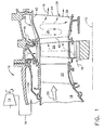
- FIG. 1 Illustrated in Figure 1 is a portion of an exemplary turbofan gas turbine engine 10 which is axisymmetrical about a longitudinal or axial centerline axis 12.
- the engine includes a multistage axial compressor 14 configured for pressurizing air 16 which is suitably channeled to an annular combustor 18, illustrated in aft part.
- Fuel is mixed with the compressed air in the combustor in a conventional manner for generating hot combustion gases 20 which flow downstream therefrom.
- a high pressure turbine includes a first stage turbine nozzle 22 which channels the combustion gases from the combustor through a row of first stage turbine rotor blades 24 which extract energy therefrom.
- the blades extend radially outwardly from a supporting disk which is joined by a shaft to the compressor for rotating the several stages of compressor rotor blades therein during operation.
- a second stage turbine nozzle 26 Disposed immediately downstream of the first stage rotor blades is a second stage turbine nozzle 26 conventionally supported to a surrounding annular casing.
- the combustion gases flow through the second stage nozzle 26 to a row of second stage turbine blades (not illustrated), and further downstream to a low pressure turbine (not shown) which may be used for powering a fan (not shown) in a conventional manner.
- first and second stage turbine nozzles 22,26 are configured for channeling the combustion gases to their respective rows of turbine rotor blades, they have substantially different configurations and cooling circuits due to their different placement in the engine.
- the first stage nozzle 22 first receives the hottest combustion gases from the combustor and requires maximum cooling features which typically include impingement baffles therein for maximizing the cooling effectiveness of the cooling air 16 being bled from the compressor and used as a coolant during operation.
- the second stage nozzle 26 receives cooler combustion gases as energy is extracted therefrom and has a simpler cooling configuration typically without use of impingement baffles therein.
- the engine 10 itself is relatively small, with the turbine components being correspondingly small, including the second stage nozzle 26.
- the small size of the second stage nozzle 26 is subject to corresponding problems in efficient cooling thereof and in the economical manufacture of the nozzle components.
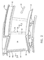
- the second stage nozzle 26 illustrated in Figure 1 is an annular assembly of components which is axisymmetrical about the centerline axis 12, and is formed by a plurality of arcuate nozzle segments 26a, one of which is illustrated in Figure 2 .
- Each segment typically includes two vanes or airfoils 28 extending radially outwardly from the centerline axis between a radially inner band 30 and a radially outer band 32 in a unitary, or one-piece construction typically formed by casting.
- the turbine nozzle airfoils 28 are substantially identical to each other, with each having first and second sidewalls 34,36 which are circumferentially or laterally opposite from each other.
- the first, or pressure, sidewall 34 is generally concave
- the second, or suction, sidewall 36 is generally convex.
- the two sidewalls extend longitudinally or radially in airfoil span between a root 38 at the inner band and an outer tip 40 at the outer band.
- the two sidewalls extend axially or chordally between a leading edge 42 and a trailing edge 44.
- the two sidewalls are spaced apart from each other in the typical crescent shape between the leading and trailing edges to define an internal cooling circuit 46 therebetween.
- the pressure sidewall of the airfoil has been removed to illustrate the internal features of the airfoil and the cooling circuit 46 along the inner surface of the suction sidewall 36.
- a plurality of venturi discharge or outlet slots 48 are arranged in a vertical row along the airfoil span terminating adjacent the trailing edge 44 and commencing inside the airfoil in flow communication with the internal cooling circuit 46 for receiving the cooling air or coolant 16 conventionally provided to the turbine nozzle from the compressor.
- FIG. 5 illustrates in greatly enlarged view the preferred form of the venturi slots 48.
- Each slot is defined in circumferential width between the inner surfaces of the two sidewalls and in radial height between complementary slot bridges 28a which extend circumferentially or laterally between the two sidewalls.
- Each slot includes in serial flow communication an inlet 48a, a converging portion 48b adjoining the inlet, a throat 48c of minimum flow area adjoining the converging portion, a diverging portion 48d adjoining the throat, and an outlet 48e adjoining the diverging portion and exposed to the vane outside adjacent the trailing edge for discharging the coolant therefrom.
- the row of slot inlets 48a receive their coolant 16 from the cooling circuit 46 and discharge that coolant axially aft toward the trailing edge for discharge initially upstream therefrom for forming a protective film of cooling air thereat.
- venturi slots illustrated in Figures 4 and 5 is precisely configured with discrete and finite length portions from inlet to outlet for advantages in manufacture and performance during operation.
- the inboard slots between the outer and inner bands may be substantially identical in configuration and size, with the two outboard slots directly adjacent the outer and inner bands being slightly larger in flow area for accommodating their local interaction with the adjacent bands.
- the slot throat 48c is a finite portion of the overall venturi slot and has an axial or chordal length A selected for suitable control of flow area in the throat and for reproducibility of the throat during casting.
- the chordal length B of the converging portion 48b is comparable or similar to the chordal length A of the throat for improving durability of the ceramic core.
- the length B may vary suitably relative to the length A, plus or minus 50% for example, and in one embodiment A is 40 mils and B is 50 mils.
- the converging portion of the outlet slots is preferably tapered in the radial span with the width thereof being substantially constant between the pressure and suction sidewalls.
- the width of the converging portion could also taper if desired.
- the converging portion 48b is separate and distinct from the slot inlet 48a, with the inlet being flared in the radial direction with a suitably large radius forming a two-dimensional bellmouth inlet into each venturi slot.
- Each venturi slot preferably blends smoothly from the flared inlet 48a continuously to the outlet 48e at its opposite end, with smooth and continuous transitions from portion-to-portion.
- the corresponding slot bridges 28a are complementarily smooth between their opposite two ends corresponding with the inlet and outlet of the venturi slot.
- the diverging portion 48d diverges with straight sides along the corresponding bridges 28a, with the upper and lower portions of the slot outlet 48e being aligned straight therewith.
- the slot outlets 48e terminate forward of the trailing edge itself and are exposed at the pressure sidewall 34, with a generally trapezoid configuration.
- venturi discharge slots 48 offer several advantages in the manufacture and operation of the turbine nozzle airfoils.
- the flared slot inlet 48a reduces the friction loss at the inlets for improving the flowrate through the slots.
- the converging, throat, and diverging portions 48b-d provide efficient flow channeling of the coolant with suitable diffusion in the diverging portion 48d from maximizing efficiency of the discharge flow.
- the diffusion or taper angle of the diverging portion may be about seven degrees, with the converging portion having a similar taper angle, with those taper angles being adjustable for maximizing efficiency in each design.
- venturi slots permit the production of a relatively long trailing edge discharge slot for minimizing the break-out distance from the trailing edge. Since the airfoil trailing edge is relatively thin, the slot outlet 48e breaks out through the pressure sidewall forward of the trailing edge itself. The coolant is thusly discharged from the airfoil beginning at the break-out distance forward of the trailing edge, which correspondingly reduces the cooling effectiveness of the coolant.
- the flared slot inlet and converging portion permit the use of a stronger ceramic core, as further described hereinbelow, allowing the venturi slot to be longer than it otherwise would, and thusly minimizing the break-out distance.
- the cooling circuit 46 includes a three-pass serpentine channel commencing at a first flow leg 46a extending in span adjacent the airfoil leading edge 42, which is in turn joined to a second or middle flow leg 46b extending in span directly aft of the first leg, and in turn joined to a third or last flow leg 46c extending in span between the middle leg and the row of venturi slots 48.
- the multi-pass serpentine circuit is fully contained between the airfoil sidewalls and outer and inner bands and has a single inlet in the outer band atop the leading edge for feeding the coolant radially inwardly through the first leg 46a.
- the first leg extends to the inner band and then bends upwardly into the middle leg 46b which extends up to the outer band, and then turns downwardly into the last leg 46c which extends down to the inner band.
- the serpentine circuit is defined by corresponding circuit bridges 28b extending laterally between the two sidewalls, and in part span between the outer and inner bands to define the three passes or channel legs of the circuit.
- the serpentine circuit may be otherwise conventionally configured with short-height turbulator ribs and pins, and bridging pins for enhancing heat transfer between the hot metal and the coolant channeled through the airfoil during operation; and with one or more intermediate outlets.
- each nozzle segment, and in particular the sidewalls 34,36 defining the individual airfoils is in the preferred form of a unitary, or one-piece casting having the cooling circuit and venturi slots being casting voids therein.
- the venturi slots 48 extend chordally from the last leg of the serpentine circuit in the casting and enjoy significant advantages in the manufacture thereof by casting as described hereinbelow.
- the cooling circuit 46 preferably also includes a plurality of axial crossover holes 46d defined between corresponding bridge pins 28c extending between the opposite airfoil sidewalls.
- the crossover holes are aligned in a row along the airfoil span and disposed axially or chordally between the venturi slots and the last serpentine leg 46c to define a common discharge channel or manifold 46e.
- the manifold extends along the airfoil span between the outer and inner bands and adjoins in flow communication all of the slot inlets 48a for discharging the coolant through the respective venturi slots during operation.
- crossover holes are their ability to introduce an additional pressure drop in the coolant channeled through the airfoils.
- the increase in aerodynamic efficiency of the flared inlet 48a and converging portion 48b can result in an undesirable increase in flowrate of the coolant through the venturi slots.
- Excessive coolant discharge decreases engine efficiency without providing any additional benefit in trailing edge cooling.
- the row of crossover holes 46d may be introduced for preferentially introducing an additional pressure drop inside the airfoil for metering flow through the cooperating venturi slots.
- the crossover holes may introduce a predetermined pressure drop in the coolant for offsetting the otherwise increase in coolant flowrate due to the increased efficiency of the flared slot inlets and converging portions.
- This configuration additionally permits casting of the venturi slots in a relatively small turbine airfoil, which would otherwise not be possible or practical due to poor ceramic core yield and due to poor airfoil casting yield associated with breakage of the ceramic core during casting.
- Ceramic core strength may be further increased by introducing generally rectangular or oval cross sections for the venturi slots 48 and crossover holes 46d as illustrated in Figures 6 and 7 .
- the flow area of the throat 48c controls the flowrate of the coolant through the venturi slot.
- the throat has a height C in the airfoil span direction, and a width D in the circumferential direction between the two sidewalls, with the four sides of the throat defining a oval with substantially straight sides and full fillets at the top and bottom thereof.
- the height E of the straight portions of the span sides of the throat is suitably smaller than the height C between the top and bottom fillet sides.
- the flow area of the rectangular throat may be conventionally calculated using the dimensions C,D.
- each of the crossover holes 46d has an oval cross section with a span height c and a lateral width d, with a span height e of the straight portions of the span sides being smaller than the height c by the corresponding full fillets at the top and bottom sides of the hole.
- the oval configurations of the crossover holes 46d and the venturi throats 48c are similar with their corresponding span heights C,c being greater than their lateral widths D,d which increases the strength of the ceramic core in the these regions due to the increased bending moment of inertia in the span direction.
- each slot inlet 48a as illustrated in Figure 5 being aligned radially with a corresponding bridge pin 28c.
- each slot bridge 28a is aligned radially in span with a corresponding crossover hole 46d. This improves cooling effectiveness at the trailing edge by impingement cooling the slot bridges 28a, while increasing the desired pressure drop in this region.
- the interconnection of the oval venturi slots and crossover holes improves the strength of the ceramic core for increasing yield thereof.
- the collective flow area of the crossover holes 46d in the entire row thereof is preferably substantially greater than the collective flow area of the throats 48c of all the venturi slots for maintaining sufficient backflow margin and a suitable pressure drop along the airfoil trailing edge region.
- Backflow margin is a conventional term of art representing the differential pressure available between the coolant and combustion gases on opposite sides of the airfoil wall.
- the crossover holes 46d and the venturi throats 48c have a corresponding flow area ratio of about 4/3, with the collective area of the former holes being greater than the collective area of the latter throats. This unique area ratio enhances backflow margin and pressure drop of the coolant being discharged.
- crossover holes and the venturi throats may be sized in flow area to effect corresponding pressure drops of about 15 percent and about 75 percent, respectively, of the total pressure drop of the coolant through the airfoil. In the exemplary configuration illustrated in Figure 4 , this may be effected by the 4/3 area ratio between the row of holes and venturi throats.
- the pressure sidewall 34 of the airfoil is generally concave and cooperates with the suction sidewall of an adjacent airfoil to effect a pressure drop in the combustion gases 20 flowable thereover during operation.
- the crossover holes and the venturi throats are sized in flow area as described above to additionally effect a collective, or total pressure drop thereacross of about 90 percent, for substantially matching the pressure drop in the combustion gases 20 as they flow outside the pressure sidewall along the region of the crossover holes and venturi slots.
- the internal pressure drop of the coolant in the trailing edge region will generally match the external pressure drop of the combustion gases for maintaining a suitable backflow margin at the site of any crack in this region.
- the so-cracked airfoil may then be operated without additionally adverse effect until the next available maintenance outage.
- the venturi configuration of the discharge slot includes several features for improving the yield of the ceramic core and airfoil casting.
- the slot converging portion 48b increases in size toward the flared slot inlet 48a, and that inlet additionally increases in size to the manifold 46e.
- the corresponding ceramic core in this region will therefore be larger than it otherwise would be and has improved strength for increasing yield.
- crossover holes 46d and venturi throats 48c have the tall oval configurations described above with a height-to-width ratio C/D or c/d preferably greater than two.
- the c/d ratio may be about 2.2, and the C/D ratio may be about 2.8.
- FIG 8 illustrates schematically a preferred method of making one of the turbine nozzle airfoils previously illustrated in Figures 1-7 .
- a ceramic core 50 is configured to correspond with the internal cooling circuit 46 and cooperating venturi slots 48 as illustrated, for example, in Figure 4 .
- the ceramic core material is solid and when used in the casting process is surrounded by molten metal which solidifies to form the metal portions of the airfoil including the thin sidewalls 34,36 between which the ceramic core is captured. Upon removal of the ceramic core from the casting, a corresponding void is created which matches the intended configurations of the cooling circuit and venturi slots.
- the manufacture of ceramic cores and the casting of nozzle segments and their airfoils is conventional.
- the nozzle segments are typically cast with two airfoils per segment in an integral unitary assembly with the outer and inner bands.
- the ceramic core 50 illustrated in Figure 8 is specifically configured in one embodiment of the present invention to include a row of axially extending core fingers 52 configured for corresponding with the venturi slots 48 of Figure 4 for example.
- the row of core fingers 52 is cantilevered from a common core leg 54 which corresponds with the discharge manifold 46e of Figure 4 .
- the remainder of the core 50 is conventionally configured for defining the three-pass serpentine cooling circuit 46a,b,c also illustrated in Figure 4 .
- Figure 8 illustrates that the core fingers are relatively long and individually supported or cantilevered integrally from the common core leg 54.
- the core fingers and leg are solid ceramic material which corresponds with the voids in Figures 5 and 6 which define the complementary features of the venturi slots and their flow communication with the common manifold 46e.
- the converging cross sections of the flared inlet 40a and adjoining converging portion 48b of each venturi slot provide increased bending moment of inertia or strength for each of the ceramic core fingers 52 where they join the common core leg 54.
- the strength of the fingers is correspondingly increased for increasing the yield of the ceramic cores for making economical the casting of these features in the resulting turbine airfoil.
- venturi discharge slots 48 and their cooperation with the crossover holes 46d has various advantages as described above in both aerodynamic performance for efficiency, and in manufacturing using conventional casting processes. These advantages are particularly useful in relatively small turbine airfoils, such as those found in turbine nozzle vanes, but could also be used in larger turbine airfoils, as well as in turbine rotor blades where desired.
- the three-pass serpentine cooling circuit illustrated in Figure 4 is fully contained within the inner and outer bands and does not require brazed cover plates on the inner or outer bands as might be found in other casting configurations.
- the three serpentine legs channel their cooling flow in series to feed the common row of crossover holes 46d which in turn feed the common manifold 46e for feeding the row of venturi discharge slots 48.
- the corresponding ceramic core 50 illustrated in Figure 8 is relatively strong, including the cantilevered core fingers 52 not otherwise interconnected except at the common core leg 54, which may have a high ceramic core yield for economically casting a large number of nozzle vane airfoils required for a particular engine application.
Description
- The present invention relates generally to gas turbine engines, and, more specifically, to turbines therein.
- In a gas turbine engine, air is pressurized in a compressor and mixed with fuel in a combustor for generating hot combustion gases which flow downstream through turbines that extract energy therefrom. High and low pressure turbines extract energy in turn for correspondingly powering the compressor and providing useful work, such as powering an upstream fan in an exemplary turbofan engine for powering an aircraft in flight.
- In aircraft applications, engine weight and efficiency are primary design objectives for maximizing aircraft range and reducing operating costs. Weight and efficiency are interrelated in the various highly sophisticated components of the modern gas turbine engine built with precision typically measured in mils, and even fractions of mils.
- Rotary turbine blades and stationary turbine nozzle vanes have corresponding airfoil profiles precisely configured for maximizing efficiency of energy extraction from the combustion gases. These components are heated by the hot combustion gases during operation, and therefore require suitable cooling for ensuring a long useful life.
- Turbine airfoil cooling is conventionally effected by forming various cooling circuits therein which are fed from air bled from the compressor used as a coolant for protecting the airfoils during operation. Diverting compressed air from the combustor correspondingly decreases efficiency of the engine, and therefore it is desired to minimize the use of parasitic cooling air while suitably protecting the hot turbine components.
- The prior art of turbine blades and nozzles is crowded with various forms of the cooling circuits therein and various forms of discharge cooling holes through the pressure and suction sidewalls of the airfoils.
- A gas turbine engine airfoil according to the prior art is shown in document
EP 1 213 442 A1 . - Turbine airfoil discharge holes are found at various locations between the leading and trailing edges of the airfoil and from root to tip thereof, and have various sizes and configurations selected to improve performance in the complex three-dimensional combustion gas flow field surrounding the airfoils. And, the airfoils are subject to complex stress distribution at the different parts thereof due to the complex temperature distribution.
- The cooling configurations of the turbine airfoils are also dependent on the physical size of the airfoils from large to small, with the smaller airfoils having additional problems for efficient cooling thereof due to the practical lower limit in size of cooling features which may be introduced therein.
- In particular, the trailing edge of a turbine airfoil is relatively thin in view of the typical aerodynamic profile of the airfoil which has a maximum thickness near the leading edge, with the two sidewalls converging to the sharp trailing edge. The internal cooling circuit of the airfoil must correspondingly decrease in size to fit between the converging sidewalls of the airfoil, and typically must terminate before reaching the trailing edge for small airfoils, or airfoils having similarly thin trailing edges.
- In order to adequately cool the airfoil trailing edge, the internal cooling circuit typically discharges into a row of trailing edge holes formed through the pressure size of the airfoil just upstream of the trailing edge. The discharge coolant provides a protective film of cooling air which travels downstream over the trailing edge for protection thereof from the hot combustion gases.
- However, for particularly small turbine airfoils on the order of several centimeters in span height, the introduction of even the minimum-size outlet hole, on the order of about 10-15 mils in diameter, may require the placement of the trailing edge holes significantly upstream from the trailing edge itself, which decreases the cooling effectiveness of the discharged air.
- Correspondingly, the minimum-size typical outlet holes may discharge more cooling air than required due to their relatively large size, and therefore decrease overall engine efficiency.
- The ability to manufacture economically turbine airfoils is another significant objective in the design process. Turbine blades and vanes are typically cast using a ceramic core for the internal cooling features thereof in the conventional lost wax casting process.
- Small features in the ceramic core correspondingly make the core fragile and subject to breaking during the manufacturing process which increases the overall cost of manufacture. Ceramic core yield is a significant factor in manufacturing turbine airfoils, and small cooling features embodied in the core are typically associated with lower yield.
- For example, the trailing edge discharge holes are particularly problematic in manufacturing turbine airfoils since they correspondingly have small features which have practical lower-size limits in the casting of small turbine airfoils. The trailing edge holes have a finite axial or chordal length and are typically arranged in a radial row disposed in flow communication with a common radial flow passage inside the airfoil. The corresponding ceramic core has a common ceramic leg with a row of cantilevered ceramic fingers representing the trailing edge holes after casting.
- For larger turbine airfoils, the ceramic core may be sufficiently strong for obtaining a sufficient yield for economically casting the airfoils. However, for small airfoils and small features the ceramic fingers would become unacceptably small and fragile leading to an unacceptable yield rendering their use in manufacture impractical.
- Instead, the small airfoil may be cast with a corresponding ceramic core omitting the ceramic fingers and the trailing edge holes for casting the airfoil. The so-cast airfoil then undergoes a subsequent manufacturing operation for drilling the trailing edge holes, typically using electrical discharge machining (EDM) or electrostream (ES) machining for achieving the small size and tolerances required for the small trailing edge holes.
- Accordingly, it is desired to provide a turbine airfoil having an improved trailing edge cooling design for increasing cooling efficiency in a configuration which may be manufactured using a corresponding ceramic core with suitable yield, even for typically small turbine airfoils.
- According to the present invention, a turbine airfoil includes sidewalls extending between leading and trailing edges, with an internal cooling circuit therein. A row of venturi slots commences inside the airfoil at the cooling circuit and terminates near the trailing edge. Each of the venturi slots includes an inlet, converging portion, throat, diverging portion, and outlet in serial flow communication from the cooling circuit. The converging portion is comparable in chordal length with the throat.
- The invention, in accordance with preferred and exemplary embodiments, together with further objects and advantages thereof, is more particularly described in the following detailed description taken in conjunction with the accompanying drawings in which:
-
Figure 1 is a partly sectional axial view of a portion of an aircraft gas turbine engine including a second stage turbine nozzle in accordance with an exemplary embodiment of the present invention. -
Figure 2 is an isometric view of the one of the several segments of the nozzle illustrated inFigure 1 . -
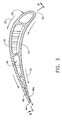
Figure 3 is a radial sectional view through one of the nozzle airfoil vanes illustrated inFigure 2 and taken along line 3-3. -
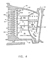
Figure 4 is an axial sectional view through one of the vanes of the nozzle illustrated inFigure 3 and taken along line 4-4. -
Figure 5 is an enlarged axial sectional view of exemplary venturi discharge slots in the trailing edge region of the airfoil illustrated inFigure 4 . -
Figure 6 is a radial sectional view through a slot throat illustrated inFigure 5 and taken along line 6-6. -
Figure 7 is a radial sectional view through a crossover hole feeding the venturi slot illustrated inFigure 5 and taken along line 7-7. -
Figure 8 is a flowchart of an exemplary method of making the turbine airfoil illustrated inFigures 1-7 . - Illustrated in
Figure 1 is a portion of an exemplary turbofangas turbine engine 10 which is axisymmetrical about a longitudinal oraxial centerline axis 12. The engine includes a multistageaxial compressor 14 configured for pressurizingair 16 which is suitably channeled to anannular combustor 18, illustrated in aft part. - Fuel is mixed with the compressed air in the combustor in a conventional manner for generating
hot combustion gases 20 which flow downstream therefrom. - A high pressure turbine includes a first stage turbine nozzle 22 which channels the combustion gases from the combustor through a row of first stage
turbine rotor blades 24 which extract energy therefrom. The blades extend radially outwardly from a supporting disk which is joined by a shaft to the compressor for rotating the several stages of compressor rotor blades therein during operation. - Disposed immediately downstream of the first stage rotor blades is a second
stage turbine nozzle 26 conventionally supported to a surrounding annular casing. The combustion gases flow through thesecond stage nozzle 26 to a row of second stage turbine blades (not illustrated), and further downstream to a low pressure turbine (not shown) which may be used for powering a fan (not shown) in a conventional manner. - Although the first and second
stage turbine nozzles 22,26 are configured for channeling the combustion gases to their respective rows of turbine rotor blades, they have substantially different configurations and cooling circuits due to their different placement in the engine. The first stage nozzle 22 first receives the hottest combustion gases from the combustor and requires maximum cooling features which typically include impingement baffles therein for maximizing the cooling effectiveness of thecooling air 16 being bled from the compressor and used as a coolant during operation. - The
second stage nozzle 26 receives cooler combustion gases as energy is extracted therefrom and has a simpler cooling configuration typically without use of impingement baffles therein. - In the preferred embodiment illustrated in
Figure 1 , theengine 10 itself is relatively small, with the turbine components being correspondingly small, including thesecond stage nozzle 26. As described above in the Background section, the small size of thesecond stage nozzle 26 is subject to corresponding problems in efficient cooling thereof and in the economical manufacture of the nozzle components. - The
second stage nozzle 26 illustrated inFigure 1 is an annular assembly of components which is axisymmetrical about thecenterline axis 12, and is formed by a plurality of arcuate nozzle segments 26a, one of which is illustrated inFigure 2 . Each segment typically includes two vanes orairfoils 28 extending radially outwardly from the centerline axis between a radiallyinner band 30 and a radiallyouter band 32 in a unitary, or one-piece construction typically formed by casting. - The
turbine nozzle airfoils 28 are substantially identical to each other, with each having first andsecond sidewalls sidewall 34 is generally concave, and the second, or suction,sidewall 36 is generally convex. The two sidewalls extend longitudinally or radially in airfoil span between aroot 38 at the inner band and anouter tip 40 at the outer band. The two sidewalls extend axially or chordally between a leadingedge 42 and atrailing edge 44. - As shown in
Figure 3 , the two sidewalls are spaced apart from each other in the typical crescent shape between the leading and trailing edges to define aninternal cooling circuit 46 therebetween. InFigure 4 , the pressure sidewall of the airfoil has been removed to illustrate the internal features of the airfoil and thecooling circuit 46 along the inner surface of thesuction sidewall 36. - As shown in
Figure 4 , a plurality of venturi discharge oroutlet slots 48 are arranged in a vertical row along the airfoil span terminating adjacent the trailingedge 44 and commencing inside the airfoil in flow communication with theinternal cooling circuit 46 for receiving the cooling air orcoolant 16 conventionally provided to the turbine nozzle from the compressor. -
Figure 5 illustrates in greatly enlarged view the preferred form of theventuri slots 48. Each slot is defined in circumferential width between the inner surfaces of the two sidewalls and in radial height betweencomplementary slot bridges 28a which extend circumferentially or laterally between the two sidewalls. Each slot includes in serial flow communication an inlet 48a, a convergingportion 48b adjoining the inlet, athroat 48c of minimum flow area adjoining the converging portion, a divergingportion 48d adjoining the throat, and anoutlet 48e adjoining the diverging portion and exposed to the vane outside adjacent the trailing edge for discharging the coolant therefrom. The row of slot inlets 48a receive theircoolant 16 from the coolingcircuit 46 and discharge that coolant axially aft toward the trailing edge for discharge initially upstream therefrom for forming a protective film of cooling air thereat. - Each of the venturi slots illustrated in
Figures 4 and5 is precisely configured with discrete and finite length portions from inlet to outlet for advantages in manufacture and performance during operation. The inboard slots between the outer and inner bands may be substantially identical in configuration and size, with the two outboard slots directly adjacent the outer and inner bands being slightly larger in flow area for accommodating their local interaction with the adjacent bands. - As shown in
Figure 5 , theslot throat 48c is a finite portion of the overall venturi slot and has an axial or chordal length A selected for suitable control of flow area in the throat and for reproducibility of the throat during casting. The chordal length B of the convergingportion 48b is comparable or similar to the chordal length A of the throat for improving durability of the ceramic core. The length B may vary suitably relative to the length A, plus or minus 50% for example, and in one embodiment A is 40 mils and B is 50 mils. - The converging portion of the outlet slots is preferably tapered in the radial span with the width thereof being substantially constant between the pressure and suction sidewalls. The width of the converging portion could also taper if desired.
- The converging
portion 48b is separate and distinct from the slot inlet 48a, with the inlet being flared in the radial direction with a suitably large radius forming a two-dimensional bellmouth inlet into each venturi slot. - Each venturi slot preferably blends smoothly from the flared inlet 48a continuously to the
outlet 48e at its opposite end, with smooth and continuous transitions from portion-to-portion. Thecorresponding slot bridges 28a are complementarily smooth between their opposite two ends corresponding with the inlet and outlet of the venturi slot. The divergingportion 48d diverges with straight sides along the correspondingbridges 28a, with the upper and lower portions of theslot outlet 48e being aligned straight therewith. As additionally illustrated inFigures 2 and3 , theslot outlets 48e terminate forward of the trailing edge itself and are exposed at thepressure sidewall 34, with a generally trapezoid configuration. - The
venturi discharge slots 48 offer several advantages in the manufacture and operation of the turbine nozzle airfoils. For example, the flared slot inlet 48a reduces the friction loss at the inlets for improving the flowrate through the slots. The converging, throat, and divergingportions 48b-d provide efficient flow channeling of the coolant with suitable diffusion in the divergingportion 48d from maximizing efficiency of the discharge flow. The diffusion or taper angle of the diverging portion may be about seven degrees, with the converging portion having a similar taper angle, with those taper angles being adjustable for maximizing efficiency in each design. - The distinct portions of the venturi slots permit the production of a relatively long trailing edge discharge slot for minimizing the break-out distance from the trailing edge. Since the airfoil trailing edge is relatively thin, the
slot outlet 48e breaks out through the pressure sidewall forward of the trailing edge itself. The coolant is thusly discharged from the airfoil beginning at the break-out distance forward of the trailing edge, which correspondingly reduces the cooling effectiveness of the coolant. The flared slot inlet and converging portion permit the use of a stronger ceramic core, as further described hereinbelow, allowing the venturi slot to be longer than it otherwise would, and thusly minimizing the break-out distance. - In the preferred embodiment illustrated in
Figure 4 , the coolingcircuit 46 includes a three-pass serpentine channel commencing at a first flow leg 46a extending in span adjacent theairfoil leading edge 42, which is in turn joined to a second ormiddle flow leg 46b extending in span directly aft of the first leg, and in turn joined to a third orlast flow leg 46c extending in span between the middle leg and the row ofventuri slots 48. - The multi-pass serpentine circuit is fully contained between the airfoil sidewalls and outer and inner bands and has a single inlet in the outer band atop the leading edge for feeding the coolant radially inwardly through the first leg 46a. The first leg extends to the inner band and then bends upwardly into the
middle leg 46b which extends up to the outer band, and then turns downwardly into thelast leg 46c which extends down to the inner band. - The serpentine circuit is defined by corresponding circuit bridges 28b extending laterally between the two sidewalls, and in part span between the outer and inner bands to define the three passes or channel legs of the circuit. The serpentine circuit may be otherwise conventionally configured with short-height turbulator ribs and pins, and bridging pins for enhancing heat transfer between the hot metal and the coolant channeled through the airfoil during operation; and with one or more intermediate outlets.
- As indicated above, each nozzle segment, and in particular the
sidewalls venturi slots 48 extend chordally from the last leg of the serpentine circuit in the casting and enjoy significant advantages in the manufacture thereof by casting as described hereinbelow. - As illustrated in
Figures 4 and5 , the coolingcircuit 46 preferably also includes a plurality ofaxial crossover holes 46d defined between corresponding bridge pins 28c extending between the opposite airfoil sidewalls. The crossover holes are aligned in a row along the airfoil span and disposed axially or chordally between the venturi slots and the lastserpentine leg 46c to define a common discharge channel or manifold 46e. The manifold extends along the airfoil span between the outer and inner bands and adjoins in flow communication all of the slot inlets 48a for discharging the coolant through the respective venturi slots during operation. - A particular advantage of the crossover holes is their ability to introduce an additional pressure drop in the coolant channeled through the airfoils. For a small turbine airfoil where the flow areas of the venturi slots are near practical minimum values, the increase in aerodynamic efficiency of the flared inlet 48a and converging
portion 48b can result in an undesirable increase in flowrate of the coolant through the venturi slots. Excessive coolant discharge decreases engine efficiency without providing any additional benefit in trailing edge cooling. - Since it is not feasible or practical to further reduce the flow area of the venturi slots in a small cast turbine airfoil, the row of
crossover holes 46d may be introduced for preferentially introducing an additional pressure drop inside the airfoil for metering flow through the cooperating venturi slots. In this way, the crossover holes may introduce a predetermined pressure drop in the coolant for offsetting the otherwise increase in coolant flowrate due to the increased efficiency of the flared slot inlets and converging portions. This configuration additionally permits casting of the venturi slots in a relatively small turbine airfoil, which would otherwise not be possible or practical due to poor ceramic core yield and due to poor airfoil casting yield associated with breakage of the ceramic core during casting. - Ceramic core strength may be further increased by introducing generally rectangular or oval cross sections for the
venturi slots 48 andcrossover holes 46d as illustrated inFigures 6 and 7 . In particular, the flow area of thethroat 48c controls the flowrate of the coolant through the venturi slot. The throat has a height C in the airfoil span direction, and a width D in the circumferential direction between the two sidewalls, with the four sides of the throat defining a oval with substantially straight sides and full fillets at the top and bottom thereof. The height E of the straight portions of the span sides of the throat is suitably smaller than the height C between the top and bottom fillet sides. The flow area of the rectangular throat may be conventionally calculated using the dimensions C,D. - Similarly, each of the
crossover holes 46d has an oval cross section with a span height c and a lateral width d, with a span height e of the straight portions of the span sides being smaller than the height c by the corresponding full fillets at the top and bottom sides of the hole. - The oval configurations of the
crossover holes 46d and theventuri throats 48c are similar with their corresponding span heights C,c being greater than their lateral widths D,d which increases the strength of the ceramic core in the these regions due to the increased bending moment of inertia in the span direction. - In the preferred embodiment illustrated in
Figure 4 for a second stage turbine nozzle configuration, there are twelve venturi slots 48a uniformly spaced along the trailing edge of the airfoil cooperating with thirteencrossover holes 46d, with each slot inlet 48a as illustrated inFigure 5 being aligned radially with a correspondingbridge pin 28c. Correspondingly, eachslot bridge 28a is aligned radially in span with acorresponding crossover hole 46d. This improves cooling effectiveness at the trailing edge by impingement cooling theslot bridges 28a, while increasing the desired pressure drop in this region. And, the interconnection of the oval venturi slots and crossover holes improves the strength of the ceramic core for increasing yield thereof. - The collective flow area of the
crossover holes 46d in the entire row thereof is preferably substantially greater than the collective flow area of thethroats 48c of all the venturi slots for maintaining sufficient backflow margin and a suitable pressure drop along the airfoil trailing edge region. Backflow margin is a conventional term of art representing the differential pressure available between the coolant and combustion gases on opposite sides of the airfoil wall. - Sufficient backflow margin is required to prevent ingestion of the hot combustion gases into the turbine airfoils during operation. The combination of the venturi slots and cooperating crossover holes has many advantages as explained above including the introduction of a suitable backflow margin with a preferential pressure drop in the coolant as it is discharged from the serpentine cooling circuit.
- In a preferred embodiment, the
crossover holes 46d and theventuri throats 48c have a corresponding flow area ratio of about 4/3, with the collective area of the former holes being greater than the collective area of the latter throats. This unique area ratio enhances backflow margin and pressure drop of the coolant being discharged. - More specifically, the crossover holes and the venturi throats may be sized in flow area to effect corresponding pressure drops of about 15 percent and about 75 percent, respectively, of the total pressure drop of the coolant through the airfoil. In the exemplary configuration illustrated in
Figure 4 , this may be effected by the 4/3 area ratio between the row of holes and venturi throats. - As illustrated in
Figure 3 , thepressure sidewall 34 of the airfoil is generally concave and cooperates with the suction sidewall of an adjacent airfoil to effect a pressure drop in thecombustion gases 20 flowable thereover during operation. The crossover holes and the venturi throats are sized in flow area as described above to additionally effect a collective, or total pressure drop thereacross of about 90 percent, for substantially matching the pressure drop in thecombustion gases 20 as they flow outside the pressure sidewall along the region of the crossover holes and venturi slots. - In this way, in the event of cracking of the airfoil in the trailing edge region at the end of the life of the airfoil, the internal pressure drop of the coolant in the trailing edge region will generally match the external pressure drop of the combustion gases for maintaining a suitable backflow margin at the site of any crack in this region. The so-cracked airfoil may then be operated without additionally adverse effect until the next available maintenance outage.
- As indicated above, for particularly small turbine airfoils it is desired to cast the entire internal cooling features, including the trailing edge discharge slots, if practical. The venturi configuration of the discharge slot includes several features for improving the yield of the ceramic core and airfoil casting. In particular, the
slot converging portion 48b increases in size toward the flared slot inlet 48a, and that inlet additionally increases in size to the manifold 46e. The corresponding ceramic core in this region will therefore be larger than it otherwise would be and has improved strength for increasing yield. - Furthermore, the
crossover holes 46d andventuri throats 48c have the tall oval configurations described above with a height-to-width ratio C/D or c/d preferably greater than two. For example, the c/d ratio may be about 2.2, and the C/D ratio may be about 2.8. -
Figure 8 illustrates schematically a preferred method of making one of the turbine nozzle airfoils previously illustrated inFigures 1-7 . Aceramic core 50 is configured to correspond with theinternal cooling circuit 46 and cooperatingventuri slots 48 as illustrated, for example, inFigure 4 . The ceramic core material is solid and when used in the casting process is surrounded by molten metal which solidifies to form the metal portions of the airfoil including thethin sidewalls - The manufacture of ceramic cores and the casting of nozzle segments and their airfoils is conventional. The nozzle segments are typically cast with two airfoils per segment in an integral unitary assembly with the outer and inner bands.
- The
ceramic core 50 illustrated inFigure 8 is specifically configured in one embodiment of the present invention to include a row of axially extendingcore fingers 52 configured for corresponding with theventuri slots 48 ofFigure 4 for example. The row ofcore fingers 52 is cantilevered from acommon core leg 54 which corresponds with thedischarge manifold 46e ofFigure 4 . The remainder of thecore 50 is conventionally configured for defining the three-pass serpentine cooling circuit 46a,b,c also illustrated inFigure 4 . -
Figure 8 illustrates that the core fingers are relatively long and individually supported or cantilevered integrally from thecommon core leg 54. The core fingers and leg are solid ceramic material which corresponds with the voids inFigures 5 and6 which define the complementary features of the venturi slots and their flow communication with thecommon manifold 46e. - The converging cross sections of the flared inlet 40a and adjoining converging
portion 48b of each venturi slot provide increased bending moment of inertia or strength for each of theceramic core fingers 52 where they join thecommon core leg 54. The strength of the fingers is correspondingly increased for increasing the yield of the ceramic cores for making economical the casting of these features in the resulting turbine airfoil. - The introduction of the specifically configured
venturi discharge slots 48 and their cooperation with thecrossover holes 46d has various advantages as described above in both aerodynamic performance for efficiency, and in manufacturing using conventional casting processes. These advantages are particularly useful in relatively small turbine airfoils, such as those found in turbine nozzle vanes, but could also be used in larger turbine airfoils, as well as in turbine rotor blades where desired. - The three-pass serpentine cooling circuit illustrated in
Figure 4 is fully contained within the inner and outer bands and does not require brazed cover plates on the inner or outer bands as might be found in other casting configurations. The three serpentine legs channel their cooling flow in series to feed the common row ofcrossover holes 46d which in turn feed thecommon manifold 46e for feeding the row ofventuri discharge slots 48. - The corresponding
ceramic core 50 illustrated inFigure 8 is relatively strong, including the cantileveredcore fingers 52 not otherwise interconnected except at thecommon core leg 54, which may have a high ceramic core yield for economically casting a large number of nozzle vane airfoils required for a particular engine application.
Claims (10)
- A gas turbine engine airfoil (28) comprising:pressure and suction sidewalls (34,36) extending longitudinally in airfoil span between a root (38) and a tip (40), and chordally between opposite leading and trailing edges (42,44), and spaced laterally apart therebetween to define an internal cooling circuit (46);a plurality of venturi slots (48) terminating adjacent said trailing edge and commencing inside said airfoil in flow communication with said cooling circuit (46);each of said venturi slots (48) including in serial flow communication a flared inlet (48a), a converging portion (48b) adjoining said inlet, a throat (48c) of minimum flow area adjoining said converging portion, a diverging portion (48d) adjoining said throat, and an outlet (48e) adjoining said diverging portion and exposed adjacent said trailing edge for discharging said coolant; andsaid slot converging portion (48b) being comparable in chordal length to said throat (48c).
- An airfoil according to claim 1 wherein each of said venturi slots (48) blends smoothly from said flared inlet (48a) to said outlet (48e).
- An airfoil according to claim 2 wherein:said cooling circuit (46) comprises a three-pass serpentine channel commencing at a first leg (46a) adjacent said leading edge (42) and terminating at a last leg (46c) adjoining said venturi slots; andsaid venturi slots (48) extend chordally from said last leg.
- An airfoil according to claim 3 wherein said cooling circuit (46) further comprises a plurality of crossover holes (46d) aligned in a row along said airfoil span, and disposed chordally between said venturi slots (48) and said last serpentine leg (46c) to define a discharge manifold (46e) adjoining said slot inlets (48a) for discharging said coolant through said venturi slots.
- An airfoil according to claim 4 wherein:said venturi slots (48) and crossover holes (46d) have oval cross sections greater in height along said airfoil span than in width between said sidewalls (34,36); andsaid crossover holes have a collective flow area greater than a collective flow area of said throats of said venturi slots.
- An airfoil according to claim 5 wherein:said sidewalls (34,36) comprise a casting, with said cooling circuit (46) and venturi slots (48) being casting voids therein;said slot outlets (48e) terminate forward of said trailing edge (44), and are exposed in said pressure sidewall (34); andsaid pressure sidewall is generally concave to effect a pressure drop in combustion gases (20) flowable thereover.
- An airfoil according to claim 6 wherein said crossover holes (46d) and slot throats (48c) have a corresponding area ratio of about 4/3.
- An airfoil according to claim 7 wherein said crossover holes (46d) and slot throats (48c) have height-to-width ratios greater than about two.
- An airfoil according to claim 6 wherein said crossover hole (46d) and said slot throats (48c) are sized in flow area to effect corresponding pressure drops of about 15 percent and about 75 percent, respectively, of the total pressure drop of said coolant through said airfoil.
- An airfoil according to claim 6 further comprising an inner band (30) integrally joined to said airfoil root (38), and an outer band (32) integrally joined to said airfoil tip (40); and
said crossover holes (46d) and said slot throats (48c) are sized in flow area to effect a collective pressure drop thereacross substantially matching pressure drop in said combustion gases (20) flowable outside said pressure sidewall along said crossover holes and venturi slots.
Applications Claiming Priority (2)
| Application Number | Priority Date | Filing Date | Title |
|---|---|---|---|
| US320971 | 1989-03-09 | ||
| US10/320,971 US6969230B2 (en) | 2002-12-17 | 2002-12-17 | Venturi outlet turbine airfoil |
Publications (3)
| Publication Number | Publication Date |
|---|---|
| EP1431514A2 EP1431514A2 (en) | 2004-06-23 |
| EP1431514A3 EP1431514A3 (en) | 2006-06-07 |
| EP1431514B1 true EP1431514B1 (en) | 2008-06-18 |
Family
ID=32392991
Family Applications (1)
| Application Number | Title | Priority Date | Filing Date |
|---|---|---|---|
| EP03257920A Expired - Fee Related EP1431514B1 (en) | 2002-12-17 | 2003-12-16 | Venturi outlet turbine airfoil |
Country Status (5)
| Country | Link |
|---|---|
| US (1) | US6969230B2 (en) |
| EP (1) | EP1431514B1 (en) |
| JP (1) | JP4540973B2 (en) |
| CN (1) | CN100339561C (en) |
| DE (1) | DE60321645D1 (en) |
Families Citing this family (51)
| Publication number | Priority date | Publication date | Assignee | Title |
|---|---|---|---|---|
| US7246999B2 (en) * | 2004-10-06 | 2007-07-24 | General Electric Company | Stepped outlet turbine airfoil |
| US7217097B2 (en) * | 2005-01-07 | 2007-05-15 | Siemens Power Generation, Inc. | Cooling system with internal flow guide within a turbine blade of a turbine engine |
| US7217088B2 (en) * | 2005-02-02 | 2007-05-15 | Siemens Power Generation, Inc. | Cooling fluid preheating system for an airfoil in a turbine engine |
| US7503749B2 (en) * | 2005-04-01 | 2009-03-17 | General Electric Company | Turbine nozzle with trailing edge convection and film cooling |
| US7762774B2 (en) * | 2006-12-15 | 2010-07-27 | Siemens Energy, Inc. | Cooling arrangement for a tapered turbine blade |
| US7722326B2 (en) * | 2007-03-13 | 2010-05-25 | Siemens Energy, Inc. | Intensively cooled trailing edge of thin airfoils for turbine engines |
| WO2009118245A1 (en) * | 2008-03-28 | 2009-10-01 | Alstom Technology Ltd | Guide vane for a gas turbine and gas turbine comprising such a guide vane |
| US8246306B2 (en) * | 2008-04-03 | 2012-08-21 | General Electric Company | Airfoil for nozzle and a method of forming the machined contoured passage therein |
| US20090293495A1 (en) * | 2008-05-29 | 2009-12-03 | General Electric Company | Turbine airfoil with metered cooling cavity |
| US8167558B2 (en) * | 2009-01-19 | 2012-05-01 | Siemens Energy, Inc. | Modular serpentine cooling systems for turbine engine components |
| US7712314B1 (en) | 2009-01-21 | 2010-05-11 | Gas Turbine Efficiency Sweden Ab | Venturi cooling system |
| US8142153B1 (en) * | 2009-06-22 | 2012-03-27 | Florida Turbine Technologies, Inc | Turbine vane with dirt separator |
| US8511990B2 (en) * | 2009-06-24 | 2013-08-20 | General Electric Company | Cooling hole exits for a turbine bucket tip shroud |
| JP2012145098A (en) | 2010-12-21 | 2012-08-02 | Toshiba Corp | Transition piece, and gas turbine |
| US8613597B1 (en) * | 2011-01-17 | 2013-12-24 | Florida Turbine Technologies, Inc. | Turbine blade with trailing edge cooling |
| EP2559854A1 (en) * | 2011-08-18 | 2013-02-20 | Siemens Aktiengesellschaft | Internally cooled component for a gas turbine with at least one cooling channel |
| US8882461B2 (en) * | 2011-09-12 | 2014-11-11 | Honeywell International Inc. | Gas turbine engines with improved trailing edge cooling arrangements |
| US9145780B2 (en) | 2011-12-15 | 2015-09-29 | United Technologies Corporation | Gas turbine engine airfoil cooling circuit |
| US9051842B2 (en) * | 2012-01-05 | 2015-06-09 | General Electric Company | System and method for cooling turbine blades |
| US9297261B2 (en) * | 2012-03-07 | 2016-03-29 | United Technologies Corporation | Airfoil with improved internal cooling channel pedestals |
| US9175569B2 (en) * | 2012-03-30 | 2015-11-03 | General Electric Company | Turbine airfoil trailing edge cooling slots |
| US9017026B2 (en) * | 2012-04-03 | 2015-04-28 | General Electric Company | Turbine airfoil trailing edge cooling slots |
| US9546550B2 (en) * | 2012-04-23 | 2017-01-17 | Thomas Francis Landon | Bypass foil |
| US20130302177A1 (en) * | 2012-05-08 | 2013-11-14 | Robert Frederick Bergholz, JR. | Turbine airfoil trailing edge bifurcated cooling holes |
| US20130302176A1 (en) * | 2012-05-08 | 2013-11-14 | Robert Frederick Bergholz, JR. | Turbine airfoil trailing edge cooling slot |
| US9145773B2 (en) | 2012-05-09 | 2015-09-29 | General Electric Company | Asymmetrically shaped trailing edge cooling holes |
| JP2014005812A (en) * | 2012-06-27 | 2014-01-16 | Hitachi Ltd | Gas turbine blade |
| US20140003937A1 (en) * | 2012-06-30 | 2014-01-02 | General Electric Company | Component and a method of cooling a component |
| US8936067B2 (en) * | 2012-10-23 | 2015-01-20 | Siemens Aktiengesellschaft | Casting core for a cooling arrangement for a gas turbine component |
| US20140208771A1 (en) * | 2012-12-28 | 2014-07-31 | United Technologies Corporation | Gas turbine engine component cooling arrangement |
| US9644539B2 (en) * | 2013-11-12 | 2017-05-09 | Siemens Energy, Inc. | Cooling air temperature reduction using nozzles |
| US20150322797A1 (en) * | 2014-05-09 | 2015-11-12 | United Technologies Corporation | Blade element cross-ties |
| EP3271554B1 (en) * | 2015-03-17 | 2020-04-29 | Siemens Energy, Inc. | Internal cooling system with converging-diverging exit slots in trailing edge cooling channel for an airfoil in a turbine engine |
| US10443398B2 (en) | 2015-10-15 | 2019-10-15 | General Electric Company | Turbine blade |
| US10370978B2 (en) | 2015-10-15 | 2019-08-06 | General Electric Company | Turbine blade |
| US10174620B2 (en) | 2015-10-15 | 2019-01-08 | General Electric Company | Turbine blade |
| US10208605B2 (en) | 2015-10-15 | 2019-02-19 | General Electric Company | Turbine blade |
| US10307816B2 (en) | 2015-10-26 | 2019-06-04 | United Technologies Corporation | Additively manufactured core for use in casting an internal cooling circuit of a gas turbine engine component |
| CN105401986B (en) * | 2015-11-30 | 2017-01-18 | 成都发动机(集团)有限公司 | Flow channel arrangement structure of aero-engine high-pressure turbine cooling air |
| WO2017095438A1 (en) | 2015-12-04 | 2017-06-08 | Siemens Aktiengesellschaft | Turbine airfoil with biased trailing edge cooling arrangement |
| US10226812B2 (en) | 2015-12-21 | 2019-03-12 | United Technologies Corporation | Additively manufactured core for use in casting an internal cooling circuit of a gas turbine engine component |
| US9932838B2 (en) * | 2015-12-21 | 2018-04-03 | General Electric Company | Cooling circuit for a multi-wall blade |
| EP3192970A1 (en) | 2016-01-15 | 2017-07-19 | General Electric Technology GmbH | Gas turbine blade and manufacturing method |
| CN105715316B (en) * | 2016-01-26 | 2017-06-27 | 北京航空航天大学 | A kind of simple exhaust frame of the band support plate of falling zigzag |
| US10260355B2 (en) | 2016-03-07 | 2019-04-16 | Honeywell International Inc. | Diverging-converging cooling passage for a turbine blade |
| US10519782B2 (en) | 2017-06-04 | 2019-12-31 | United Technologies Corporation | Airfoil having serpentine core resupply flow control |
| US10619489B2 (en) * | 2017-09-06 | 2020-04-14 | United Technologies Corporation | Airfoil having end wall contoured pedestals |
| FR3094033B1 (en) * | 2019-03-22 | 2021-06-11 | Safran Aircraft Engines | TURBOMACHINE BLADE EQUIPPED WITH AN OPTIMIZED COOLING CIRCUIT |
| US11352902B2 (en) * | 2020-08-27 | 2022-06-07 | Aytheon Technologies Corporation | Cooling arrangement including alternating pedestals for gas turbine engine components |
| US11168570B1 (en) * | 2020-08-27 | 2021-11-09 | Raytheon Technologies Corporation | Cooling arrangement for gas turbine engine components |
| CN113107611B (en) * | 2021-04-22 | 2022-07-12 | 南京航空航天大学 | Turbine blade trailing edge cooling structure based on double-throat pneumatic vectoring nozzle and trailing path control method thereof |
Family Cites Families (17)
| Publication number | Priority date | Publication date | Assignee | Title |
|---|---|---|---|---|
| US3533711A (en) | 1966-02-26 | 1970-10-13 | Gen Electric | Cooled vane structure for high temperature turbines |
| GB1355558A (en) * | 1971-07-02 | 1974-06-05 | Rolls Royce | Cooled vane or blade for a gas turbine engine |
| US4197443A (en) | 1977-09-19 | 1980-04-08 | General Electric Company | Method and apparatus for forming diffused cooling holes in an airfoil |
| US4303374A (en) | 1978-12-15 | 1981-12-01 | General Electric Company | Film cooled airfoil body |
| GB2121483B (en) | 1982-06-08 | 1985-02-13 | Rolls Royce | Cooled turbine blade for a gas turbine engine |
| US4601638A (en) | 1984-12-21 | 1986-07-22 | United Technologies Corporation | Airfoil trailing edge cooling arrangement |
| US4676719A (en) | 1985-12-23 | 1987-06-30 | United Technologies Corporation | Film coolant passages for cast hollow airfoils |
| US5246341A (en) | 1992-07-06 | 1993-09-21 | United Technologies Corporation | Turbine blade trailing edge cooling construction |
| US5368441A (en) | 1992-11-24 | 1994-11-29 | United Technologies Corporation | Turbine airfoil including diffusing trailing edge pedestals |
| US5288207A (en) * | 1992-11-24 | 1994-02-22 | United Technologies Corporation | Internally cooled turbine airfoil |
| EP0670955B1 (en) | 1992-11-24 | 2000-04-19 | United Technologies Corporation | Coolable airfoil structure |
| US5688104A (en) * | 1993-11-24 | 1997-11-18 | United Technologies Corporation | Airfoil having expanded wall portions to accommodate film cooling holes |
| US5741117A (en) * | 1996-10-22 | 1998-04-21 | United Technologies Corporation | Method for cooling a gas turbine stator vane |
| US6132169A (en) | 1998-12-18 | 2000-10-17 | General Electric Company | Turbine airfoil and methods for airfoil cooling |
| EP1191189A1 (en) * | 2000-09-26 | 2002-03-27 | Siemens Aktiengesellschaft | Gas turbine blades |
| EP1213442B1 (en) * | 2000-12-05 | 2009-03-11 | United Technologies Corporation | Rotor blade |
| US6602047B1 (en) * | 2002-02-28 | 2003-08-05 | General Electric Company | Methods and apparatus for cooling gas turbine nozzles |
-
2002
- 2002-12-17 US US10/320,971 patent/US6969230B2/en not_active Expired - Fee Related
-
2003
- 2003-12-16 JP JP2003417403A patent/JP4540973B2/en not_active Expired - Fee Related
- 2003-12-16 DE DE60321645T patent/DE60321645D1/en not_active Expired - Lifetime
- 2003-12-16 EP EP03257920A patent/EP1431514B1/en not_active Expired - Fee Related
- 2003-12-17 CN CNB2003101209730A patent/CN100339561C/en not_active Expired - Fee Related
Also Published As
| Publication number | Publication date |
|---|---|
| EP1431514A2 (en) | 2004-06-23 |
| US20040115053A1 (en) | 2004-06-17 |
| CN100339561C (en) | 2007-09-26 |
| CN1512036A (en) | 2004-07-14 |
| JP2004197740A (en) | 2004-07-15 |
| DE60321645D1 (en) | 2008-07-31 |
| EP1431514A3 (en) | 2006-06-07 |
| JP4540973B2 (en) | 2010-09-08 |
| US6969230B2 (en) | 2005-11-29 |
Similar Documents
| Publication | Publication Date | Title |
|---|---|---|
| EP1431514B1 (en) | Venturi outlet turbine airfoil | |
| US7674093B2 (en) | Cluster bridged casting core | |
| US8210814B2 (en) | Crossflow turbine airfoil | |
| EP1688587B1 (en) | Funnel fillet turbine stage | |
| EP1467064B1 (en) | Cooled Hollow airfoil | |
| EP1008724B1 (en) | Gas turbine engine airfoil | |
| US7572102B1 (en) | Large tapered air cooled turbine blade | |
| EP1221538B1 (en) | Cooled turbine stator blade | |
| US6984103B2 (en) | Triple circuit turbine blade | |
| EP1760267B1 (en) | Turbine rotor blade | |
| US6602047B1 (en) | Methods and apparatus for cooling gas turbine nozzles | |
| US20110236178A1 (en) | Branched airfoil core cooling arrangement | |
| EP1088964A2 (en) | Slotted impingement cooling of airfoil leading edge | |
| US6629817B2 (en) | System and method for airfoil film cooling | |
| US6382908B1 (en) | Nozzle fillet backside cooling | |
| JP4482273B2 (en) | Method and apparatus for cooling a gas turbine nozzle | |
| JP4245873B2 (en) | Turbine airfoils for gas turbine engines |
Legal Events
| Date | Code | Title | Description |
|---|---|---|---|
| PUAI | Public reference made under article 153(3) epc to a published international application that has entered the european phase |
Free format text: ORIGINAL CODE: 0009012 |
|
| AK | Designated contracting states |
Kind code of ref document: A2 Designated state(s): AT BE BG CH CY CZ DE DK EE ES FI FR GB GR HU IE IT LI LU MC NL PT RO SE SI SK TR |
|
| AX | Request for extension of the european patent |
Extension state: AL LT LV MK |
|
| PUAL | Search report despatched |
Free format text: ORIGINAL CODE: 0009013 |
|
| AK | Designated contracting states |
Kind code of ref document: A3 Designated state(s): AT BE BG CH CY CZ DE DK EE ES FI FR GB GR HU IE IT LI LU MC NL PT RO SE SI SK TR |
|
| AX | Request for extension of the european patent |
Extension state: AL LT LV MK |
|
| 17P | Request for examination filed |
Effective date: 20061207 |
|
| AKX | Designation fees paid |
Designated state(s): DE FR GB |
|
| GRAP | Despatch of communication of intention to grant a patent |
Free format text: ORIGINAL CODE: EPIDOSNIGR1 |
|
| GRAS | Grant fee paid |
Free format text: ORIGINAL CODE: EPIDOSNIGR3 |
|
| GRAA | (expected) grant |
Free format text: ORIGINAL CODE: 0009210 |
|
| AK | Designated contracting states |
Kind code of ref document: B1 Designated state(s): DE FR GB |
|
| REG | Reference to a national code |
Ref country code: GB Ref legal event code: FG4D |
|
| REF | Corresponds to: |
Ref document number: 60321645 Country of ref document: DE Date of ref document: 20080731 Kind code of ref document: P |
|
| PLBE | No opposition filed within time limit |
Free format text: ORIGINAL CODE: 0009261 |
|
| STAA | Information on the status of an ep patent application or granted ep patent |
Free format text: STATUS: NO OPPOSITION FILED WITHIN TIME LIMIT |
|
| 26N | No opposition filed |
Effective date: 20090319 |
|
| REG | Reference to a national code |
Ref country code: FR Ref legal event code: PLFP Year of fee payment: 13 |
|
| PGFP | Annual fee paid to national office [announced via postgrant information from national office to epo] |
Ref country code: GB Payment date: 20151229 Year of fee payment: 13 |
|
| PGFP | Annual fee paid to national office [announced via postgrant information from national office to epo] |
Ref country code: FR Payment date: 20151217 Year of fee payment: 13 |
|
| PGFP | Annual fee paid to national office [announced via postgrant information from national office to epo] |
Ref country code: DE Payment date: 20151229 Year of fee payment: 13 |
|
| REG | Reference to a national code |
Ref country code: DE Ref legal event code: R119 Ref document number: 60321645 Country of ref document: DE |
|
| GBPC | Gb: european patent ceased through non-payment of renewal fee |
Effective date: 20161216 |
|
| REG | Reference to a national code |
Ref country code: FR Ref legal event code: ST Effective date: 20170831 |
|
| PG25 | Lapsed in a contracting state [announced via postgrant information from national office to epo] |
Ref country code: FR Free format text: LAPSE BECAUSE OF NON-PAYMENT OF DUE FEES Effective date: 20170102 |
|
| PG25 | Lapsed in a contracting state [announced via postgrant information from national office to epo] |
Ref country code: DE Free format text: LAPSE BECAUSE OF NON-PAYMENT OF DUE FEES Effective date: 20170701 Ref country code: GB Free format text: LAPSE BECAUSE OF NON-PAYMENT OF DUE FEES Effective date: 20161216 |