BACKGROUND OF THE INVENTION
-
The present invention relates to a contact detecting device
having a cord-shaped pressure sensitive sensor provided on a
contact detecting object and serving to accurately and rapidly
detect that a part of a thing or a human body comes in contact
with the contact detecting object with a pulse output obtained
by applying force to the cord-shaped pressure sensitive sensor,
and a vehicle comprising the contact detecting device.
-
Conventionally, a contact detecting device of this type
and a running device have detected a contact with an obstacle
by means of a bumper sensor comprising a tape switch (for example,
see Japanese Patent Document JP-A-8-58501.
-
Figs. 10A and 10B are views showing a running device
comprising a conventional contact detecting device described
in the Patent Document 1, Fig. 10A being a schematic view showing
a side surface and Fig. 10B being a schematic view showing a
planar section.
-
In Figs. 10A and 10B, 80 denotes a running device, 81 denotes
a running device body, 82 denotes a truck, 83 denotes a driving
wheel, 84 denotes a driven wheel, 84a denotes a front driven
wheel and 84b denotes a rear driven wheel. 85 denotes a bumper.
86 denotes a bumper sensor comprising a tape switch. Thus, the
conventional contact detecting device has such a structure that
the tape switch 86 is provided around the bumper 85. When an
obstacle comes in contact with the bumper 85 while the running
device 80 is running, the tape switch of the bumper sensor 86
is turned ON so that the contact of the obstacle is detected.
When the bumper sensor 86 detects the contact of the obstacle,
the driving operation of the driving wheel 83 is stopped.
-
Moreover, since the bumper sensor 86 is the tape switch,
it is turned ON if a small rounded portion is present in a provision
portion. As shown in the drawing, therefore, it is necessary
to form an insertion hole 85b inserting the bumper sensor 86
on both sides of a corner section 85a of the bumper 85 and to
provide the bumper sensor 86 excluding the small rounded portion
such as the corner section 85a.
-
With the structures of the conventional contact detecting
device and the conventional running device, however, the
insertion hole 85b inserting the bumper sensor 86 is provided
on both sides of the corner section 85a, and furthermore, the
bumper sensor 86 is to be inserted therein. For this reason,
there is a problem in that a great deal of time and labor is
taken and the hole is made to give a poor appearance.
-
In order to previously solve the problem, therefore, it
is provided a cord-shaped pressure sensitive sensor around a
bumper, thereby eliminating the necessity for forming an
insertion hole on both sides of a corner section.
-
Description will be briefly given to the reason why an
ON state is not brought even if the cord-shaped pressure sensitive
sensor is bent and provided in the corner section of a bumper
perpendicularly.
-
The cord-shaped pressure sensitive sensor is a
cable-shaped sensor using a piezoelement material, and Fig. 1
shows a structure thereof. In Fig. 1, 10 denotes a cord-shaped
pressure sensitive sensor in which a core (a center electrode)
1 is provided on a center in an axial direction and the center
electrode 1 is covered with a piezoelement material 2, and
furthermore, a ground electrode 3 is provided around the
piezoelement material 2 and an outermost periphery is covered
with a PVC (vinyl chloride resin) 4.
-
The cord-shaped pressure sensitive sensor 10 uses, for
the piezoelement material 2, a resin-based material having a
heat resistance which was developed originally by the applicant
and has a working temperature of 120°C or less, and can be used
in a higher temperature region (120°C or less) than 90°C to be
a maximum working temperature of a polymer piezoelement material
(uniaxial drawn polyvinylidene fluoride) and a piezoelement
material (a piezoelement material of chloroprene and
piezoelectric ceramic powder) which are conventionally typical.
The piezoelement material 2 is constituted by a resin having
a flexibility and piezoelectric ceramic, and furthermore, is
constituted by using a flexible electrode comprising a
coil-shaped metallic center electrode and a film-shaped ground
electrode and has a flexibility which is equivalent to that of
an ordinary vinyl cord.
-
Furthermore, the cord-shaped pressure sensitive sensor
10 has a high sensitivity which is equivalent to that of the
polymer piezoelement material, and has a high sensitivity which
is equivalent to that of the polymer piezoelement material in
such a low frequency region (10 Hz or less) as to detect the
pinching of a human body. The reason is that the dielectric
constant (approximately 55) of the piezoelement material 2 is
greater than that (approximately 10) of the polymer piezoelement
material and a reduction in the sensitivity is therefore small
also in the low frequency region (10 Hz or less).
-
The piezoelement material 2 is constituted by a complex
including a resin-based material and piezoelectric ceramic
powder having a size of 10 µm or less, and an oscillation detecting
characteristic can be realized by ceramic and a flexibility can
be realized by a resin. The piezoelement material 2 can realize
a high heat resistance (120°C) and a flexibility which can easily
be obtained by compounding an amorphous polyethylene based resin
(a molecular weight of approximately 300, 000) and an amorphous
polyethylene based resin (a molecular weight of approximately
100, 000) as a resin based-material, and can carry out a simple
manufacturing process which does not require bridging.
-
The cord- shaped pressure sensitive sensor 10 thus obtained
has no piezoelectric performance with the piezoelement material
2 molded. By applying a high DC voltage of several kV/mm to
the piezoelement material 2, therefore, it is necessary to carry
out a processing (a polarization processing) of giving the
piezoelectric performance to the piezoelement material 2. The
polarization processing is carried out by forming the center
electrode 1 and the ground electrode 3 on the piezoelement
material 2 and then applying a high DC voltage to both of the
electrodes. In the case in which a very small defect such as
a crack is present in the piezoelement material 2, a discharge
is carried out in the defect portion so that both of the electrodes
are apt to be short-circuited. Consequently, a sufficient
polarization voltage cannot be applied. In the invention,
however, an original polarizing step using an auxiliary electrode
capable of adhering to the piezoelement material 2 having a
constant length is established so that a defect can be detected
and avoided to stabilize polarization. Consequently, an
increase in a length of several tens meters or more can also
be implemented.
-
In the cord-shaped pressure sensitive sensor, moreover,
a coil-shaped metallic center electrode is used for the center
electrode 1 and a film-shaped electrode (a three-layer laminated
film comprising aluminum - polyethylene terephthalate -
aluminum) is used for the ground electrode 3. Consequently,
the adhesion of the piezoelement material 2 and the electrode
can be maintained and the connection of an external lead wire
can easily be carried out so that a flexible cable-shaped mounting
structure can be obtained.
-
The center electrode 1 is formed of a copper - silver alloy
coil, the ground electrode 3 is formed of the three-layer
laminated film comprising aluminum-polyethylene terephthalate
- aluminum, the piezoelement material 2 is formed of a
polyethylene based resin and piezoelectric ceramic powder, and
a housing is formed of thermoplastic. Consequently, a
dielectric constant is 55, an electric charge generation amount
is 10 to 13 C (coulomb) / gf, and a maximum working temperature
is 120°C.
-
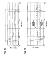
Figs. 2A and 2B are charts showing a load applied to the
cord-shaped pressure
sensitive sensor 10 and a sensor output
characteristic. The applicant conducted an experiment on the
relationship between the load of the cord-shaped pressure
sensitive sensor 10 and the sensor output. As a result, when
a bending load shown in Fig. 2A is applied to the cord-shaped
pressure
sensitive sensor 10, the sensor output presents a
phenomenon shown in Fig. 2B.
- (1) More specifically, when the load is not applied to the
cord-shaped pressure sensitive sensor 10 at a time t0, the sensor
output indicates 2(V).
- (2) When a bending load is applied to the cord-shaped pressure
sensitive sensor 10 in a constant direction at a time t1, the
sensor output is increased to 4 (V) the moment the bending load
is applied and is then inverted to 0(V) immediately, and is
thereafter returned to 2(V) again.
- (3) Subsequently, the sensor output is maintained to be 2 (V)
with bending.
- (4) When the cord-shaped pressure sensitive sensor 10 is
returned to an original state at a time t3, the sensor output
is decreased to 0.8 (V) instantaneously and is then inverted to
2.2 (V) immediately, and is thereafter returned to 2 (V) again.
-
-
In the cord-shaped pressure sensitive sensor, thus, a
signal is output only the moment force is applied. Even if the
force is then applied continuously, an output is not sent any
longer until a fluctuation is generated. Similarly, the
cord-shaped pressure sensitive sensor has such a characteristic
that the output is sent the moment the force is removed. Also
in the case in which the cord-shaped pressure sensitive sensor
is bent and provided perpendicularly in the corner section of
a bumper, accordingly, it is brought into an ON state the moment
it is bent, and the output is not sent after the completion of
the provision. Then, the output is sent when force is applied
to any part of the cord-shaped pressure sensitive sensor.
-
If the cord-shaped pressure sensitive sensor is provided
around the bumper, thus, it is not necessary to provide an
insertion hole on both sides of the corner section.
-
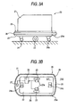
Figs. 3A and 3B are view showing a running device having
the cord-shaped pressure sensitive sensor provided around a
bumper, Fig. 3A being a schematic view showing a side surface
and Fig. 3B being a schematic view showing a planar section.
-
In Fig. 3A, 20 denotes a running device, 21 denotes a running
device body, 22 denotes a truck, 23 denotes a pair of left and
right driving wheels, 23a denotes a motor for driving the wheels,
24 denotes a driven wheel, 24a denotes a front driven wheel and
24b denotes a rear driven wheel. Moreover, 25 denotes a bumper
and 26 denotes a bumper sensor unit. The cord-shaped pressure
sensitive sensor 10 (Fig. 1) is provided in the bumper sensor
unit 26.
-
In Fig. 3B, furthermore, 27 denotes contact detecting means
for detecting an output from the cord-shaped pressure sensitive
sensor 10, and 28 denotes driving control means of the motor
23a for driving the pair of left and right driving wheels 23.
-
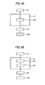
Fig. 4A is a block diagram showing the contact detecting
means 27 in Fig. 3.
-
In Fig. 4A, the contact detecting means 27 comprises a
contact detecting section 27b for detecting the contact of an
obstacle based on the output signal of the cord-shaped pressure
sensitive sensor 10 upon receipt of the same signal. A signal
output from the contact detecting section 27b is given to the
driving control means 28, and the driving control means 28
immediately stops the motor 23a upon receipt of the same signal,
thereby stopping the driving operation of the pair of left and
right driving wheels 23.
-
Thus, the contact detecting device 27 is constituted by
the bumper sensor unit 26 including the cord-shaped pressure
sensitive sensor 10 and the contact detecting means 27. The
bumper sensor unit 26 is attached to the bumper 25 provided around
the running device body 21 as shown in Fig. 5A.
-
Figs. 5A and 5B are enlarged sectional views showing a
bumper sensor unit to be a contact detecting device attached
to a bumper, and Fig. 5A is a sectional view taken along an A
- A line in Fig. 3B. Fig. 5B is a sectional view showing a bumper
sensor unit according to the invention which will be described
below.
-
In Fig. 5A, the bumper sensor unit 26 shown in Fig. 3 is
constituted by an elastic fixing member 30 to be fixed to the
bumper 25 through a fixing plate 38 with a fixing screw 39, and
the cord-shaped pressure sensitive sensor 10 shown in Fig. 1
which is provided in the elastic fixing member 30.
-
The cord-shaped pressure sensitive sensor 10 is obtained
by coaxially molding the center electrode 1, the piezoelement
material 2 and the ground electrode 3 as described with reference
to Fig. 1. A piezoelement material comprising a mixture of a
resin based material and piezoelectric ceramics powder is used
for the piezoelement material 2, and the piezoelement material
2 has a flexibility as a whole sensor.
-
On the other hand, the elastic fixing member 30 is formed
by using rubber or thermoplastic elastomer including a space
for accommodating the cord-shaped pressure sensitive sensor 10,
a gap section 32 for accommodating the fixing plate 38, and a
hollow section 35 for forming an elasticity. The hollow section
35 has a rib 31 for maintaining shapes provided on a center in
such a manner that the elastic fixingmember 30 is neither deformed
by a dead weight nor crushed by a corner section 25a of the running
device body 21. In the elastic fixing member 30, the fixing
plate 38 is inserted in the gap section 32 and is secured to
the bumper 25 with the screw 39 in a cantilever condition. When
the cord-shaped pressure sensitive sensor 10 is to be provided
in the elastic fixing member 30, it is preferable that a tongue
section 33 should be turned up and a slit section 34 should be
opened to slide and put in the cord-shaped pressure sensitive
sensor 10.
-
Moreover, it is preferable that a dimension L in a height
direction of the elastic fixing member 30 should be set to be
greater than a distance at which the running device runs while
the contact detecting means 27 detects a contact with an obstacle
and the control means 28 then controls the stop of running.
-
By the structure described above, the running device 20
outputs a signal to the contact detecting means 27 when the
cord-shaped pressure sensitive sensor 10 provided around the
bumper 25 senses a contact, and the contact detecting means 27
decides the contact of the obstacle based on the same signal
to send an output signal from the contact detecting section 27b
to the driving control means 28, and the driving control means
28 stops themotor 23a immediately upon receipt of the same signal,
thereby stopping the driving operation of the pair of left and
right driving wheels 23. Consequently, the running device 20
is stopped while the elastic fixing member 30 is deformed. Thus,
the bumper 25 can be prevented from colliding with the obstacle.
Thus, the running device is safely used as an automated guided
vehicle when a baggage is to be carried automatically.
-
Byusing the cord-shaped pressure sensitive sensor 10 (Fig.
1) in place of the bumper sensor comprising the tape switch
described in the Patent Document 1, thus, a signal is output
only the moment force is applied and the output is not sent any
longer until a fluctuation is caused even if the force is then
applied continuously. Consequently, it is possible to produce
a great advantage that the insertion hole does not need to be
provided on both sides of the corner section of the bumper.
-
However, since the cord-shaped pressure sensitive sensor
has an excessively high sensitivity, it reacts to a fine
oscillation during the running operation of the running device
in some cases. Moreover, there is a problem in that the pressure
sensitive sensor reacts to a great impact generated when the
running device runs on a step, and erroneously detects the impact.
-
The erroneous detection is rather desirable in respect
of fail-safe, and is not preferable in respect of a workability
when stopping is carried out without a contact.
SUMMARY OF THE INVENTION
-
The invention has been made to solve these problems and
has an object to provide a contact detecting device for accurately
detecting the contact of a thing or a human body and reducing
the erroneous detection of the oscillation of a vehicle body
during running as much as possible, and a vehicle comprising
the same device.
-
In order to attain the object, a first aspect of the
invention is directed to a contact detecting device comprising
a cord-shaped pressure sensitive sensor provided on a contact
detecting object and contact detecting means for detecting a
contact of a thing with the contact detecting object based on
a signal output from the cord-shaped pressure sensitive sensor,
wherein the contact detecting means includes a filtering section
for removing an oscillation frequency component of the contact
detecting object from the signal output from the cord-shaped
pressure sensitive sensor.
-
Consequently, the cord-shaped pressure sensitive sensor
generates the output signal corresponding to the acceleration
of deformation. Even if the piezoelectric sensor is provided
along the corner section of a running device, therefore, error
detection can be prevented. In addition, an oscillation during
the running operation of the running device can be prevented
from being picked up by the filtering section for removing the
oscillation frequency component of the contact detecting object
so that the erroneous detection can be prevented.
-
A second aspect of the invention is directed to the contact
detecting device according to the first aspect of the invention,
wherein the filtering section serves to remove a frequency
component including a natural frequency of the contact detecting
object.
-
Thus, the filtering section has such a structure as to
remove the frequency component including the natural frequency
of the contact detecting object. By checking the natural
frequency of the contact detecting object, thus, it is possible
to easily determine the filtering characteristic of the filtering
section.
-
A third aspect of the invention is directed to a contact
detecting device comprising a cord-shaped pressure sensitive
sensor provided on a contact detecting object and contact
detecting means for detecting a contact of a thing with the contact
detecting object based on a signal output from the cord-shaped
pressure sensitive sensor, wherein the cord-shaped pressure
sensitive sensor is provided on the contact detecting object
through support means having a different oscillation
characteristic from a natural oscillation characteristic of the
contact detecting object.
-
Consequently, the cord-shaped pressure sensitive sensor
generates the output signal corresponding to the acceleration
of deformation. Even if the piezoelectric sensor is provided
along the corner section of a running device, therefore, error
detection can be prevented. In addition, an oscillation during
the running operation of the running device can be prevented
from being picked up by the support means having a different
oscillation characteristic from the natural oscillation
characteristic so that the erroneous detection can be prevented.
-
A fourth aspect of the invention is directed to the contact
detecting device according to the first or second aspect of the
invention, wherein the cord-shaped pressure sensitive sensor
is provided on the contact detecting object through support means
having a different oscillation characteristic from a natural
oscillation characteristic of the contact detecting object.
-
Consequently, the double countermeasures are taken.
Therefore, it is possible to more reliably prevent the erroneous
detection in which the oscillation during the running operation
of the running device is picked up.
-
A fifth aspect of the invention is directed to the contact
detecting device according to any of the first to fourth aspects
of the invention, wherein the contact detecting object includes
an automated guided vehicle or a bumper of a vehicle, a security
object, a power window of a vehicle, or an automatic door of
an elevator or a house entrance.
-
A sixth aspect of the invention is directed to an automated
guided vehicle, a vehicle, a security object or an elevator
comprising the contact detecting device according to any of the
first to fourth aspects of the invention and having control means
for controlling opening and closing means based on a signal output
from the contact detecting device.
-
Consequently, the automated guided vehicle or the bumper
of a vehicle, the security object or the power window of a vehicle,
or the automatic door of an elevator or a house entrance can
be prevented from malfunctioning due to a noise other than
original detection.
-
Preferably, in the above described contact detecting
device, the support means including at least a first deformation
section having a first elastic modulus and serving to increase
deformation of the pressure sensitive sensor, and a second
deformation section having a second elastic modulus which is
higher than the first elastic modulus.
-
In the case in which external force is suddenly applied
to the pressure sensitive sensor, a time taken from the start
of a contact to the end thereof is recognized based on a signal
output from the piezoelectric sensor and a driving operation
for this period can be locked. Also in the case in which external
force is applied under a static pressure in which a pressure
is preloaded to the pressure sensitive sensor, moreover, the
second deformation section of the support member is deformed
so that a signal having a sufficient output level can be obtained
from the piezoelectric sensor and reliable detection can be
carried out.
BRIEF DESCRIPTION OF THE DRAWINGS
-
- Fig. 1 is a view showing the structure of a cord-shaped
pressure sensitive sensor to be used in the invention;
- Figs. 2A and 2B are charts showing a load applied to the
cord-shaped pressure sensitive sensor and a sensor output
characteristic;
- Figs. 3A and 3B are views showing a running device in which
the cord-shaped pressure sensitive sensor is provided around
a bumper, Fig. 3A being a schematic view showing a side surface
and Fig. 3B being a schematic view showing a planar section;
- Figs. 4A and 4B are block diagrams showing contact
detecting means;
- Figs. 5A and 5B are enlarged sectional views showing a
bumper sensor unit to be a contact detecting device, Fig. 5A
being a sectional view taken along an A - A line in Fig. 3B and
Fig. 5B being a sectional view showing a bumper sensor unit
according to the invention;
- Fig. 6 is a characteristic chart showing the filtering
frequency characteristic of a filtering section;
- Figs. 7A to 7D are charts for explaining the operation
and function of contact detecting means by the cord-shaped
pressure sensitive sensor, Fig. 7A being a characteristic chart
showing an output signal VS of a cord-shaped pressure sensitive
sensor 10, Fig. 7B being a characteristic chart showing an output
signal Vf of a filtering section 27a, Fig. 7C being a
characteristic chart showing a decision output J of contact
detecting means 27 and Fig. 7D being a characteristic chart
showing a voltage Vm applied to amotor 23a, and an axis of abscissa
indicating a time t in common to all the charts;
- Figs. 8A to 8C are views illustrating an elastic fixing
member having a different oscillation characteristic from the
natural oscillation characteristic of the running device;
- Figs. 9A and 9B are views illustrating another example
in which the cord-shaped pressure sensitive sensor is applied,
Fig. 9A showing an example of application to the power window
of a vehicle and Fig. 9B showing an example of application to
the automatic door of an elevator;
- Figs. 10A and 10B are view showing a running device
comprising a conventional contact detecting device, Fig. 10A
being a schematic view showing a side surface and Fig. 10B being
a schematic view showing a planar section;
- Fig. 11 is a view showing the appearance of an object
detecting device comprising a pressure sensitive sensor and an
opening and closing device according to the invention;
- Fig . 12 is a view showing the structure of an
A - A section in Fig. 11;
- Fig. 13 is a view showing the structure of the section
of a piezoelectric sensor;
- Fig. 14 is a view showing the appearance of the
piezoelectric sensor;
- Fig. 15 is a block diagram showing the object detecting
device and the opening and closing device;
- Fig. 16 is an explanatory view showing the state of the
pressure sensitive sensor which is obtained when an object enters
and is pinched between a window frame and a windowpane;
- Figs. 17A to 17C are characteristic charts showing an
output signal sent from a filtering section, the decision output
of deciding means and a voltage applied to a motor;
- Figs. 18Aand 18B are another characteristic charts showing
the output signal sent from the filtering section and the decision
output of the deciding means;
- Figs. 19A to 19C are views showing a state in which a pressure
is detected in a compression state, Fig. 19A being an explanatory
view showing the application of a static load, Fig. 19B being
an explanatory view showing a state in which a pressure is further
applied, and Fig. 19C being an explanatory view showing a state
in which a pressure is detected to return a windowpane;
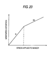
- Fig. 20 is a graph representing the deformation
characteristics of a first deformation section and a second
deformation section;
- Fig. 21 is a sectional view showing a first variant in
which a second deformation section is constituted separately
from a weather strip;
- Fig. 22 is a sectional view showing a structure according
to a second variant in which a second deformation section and
a first deformation section are integrated;
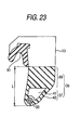
- Fig. 23 is a sectional view showing a structure according
to a third variant in which a second deformation section and
a first deformation section are integrated;
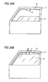
- Figs. 24A and 24B are views showing a state in which an
object presses a pressure sensitive sensor during the closing
operation of a windowpane, Fig. 24A being an explanatory view
showing a state obtained before the deformation of a window frame
and Fig. 24B being an explanatory view showing a state obtained
after the deformation of the window frame;
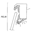
- Fig. 25 is a sectional view showing an example in which
a conventional pressure sensitive sensor for generating an output
signal corresponding to an acceleration component is attached
to a window frame;
-
DETAILED DESCRIPTION OF THE PREFERRED EMBODIMENTS
-
Embodiments of the invention will be described below in
detail with reference to the drawings.
(First Embodiment)
-
Fig. 4B is a block diagram showing contact detecting means
27 according to a first embodiment of the invention. Fig. 4B
is different from Fig. 4A in that the contact detecting means
27 comprises a filtering section 27a for removing an oscillation
frequency component during the running operation of a running
device 20 in response to a signal output from a cord-shaped
pressure sensitive sensor 10, and other structures are the same
and a contact detecting section 27b for detecting the contact
of an obstacle based on a signal output from the filtering section
27a is provided.
-
By such a structure, when the contact detecting means 27
receives the signal output from the cord-shaped pressure
sensitive sensor 10, the filtering section 27a removes a portion
based on the oscillation frequency component during the running
operation of the running device 20, and sends only the contact
signal of a true obstacle to the contact detecting section 27b.
The contact detecting section 27b sends an output signal to
driving control means 28 and the driving control means 28 stops
a motor 23a immediately after receiving the same signal, thereby
stopping the driving operation of a pair of left and right driving
wheels 23.
-
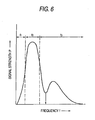
Fig. 6 is a characteristic chart showing the filtering
frequency characteristic of the filtering section 27a.
-
In Fig. 6, an axis of ordinate P indicates a signal strength
and an axis of abscissa f indicates a frequency. The filtering
section 27a shown in Fig. 4 has a filtering characteristic for
removing an oscillation frequency component f3 during the running
operation of the running device 20. The frequency component
f3 can be obtained experimentally and usually includes a natural
frequency f0 of a body 1. Therefore, a filtering characteristic
may be determined in such a manner that the natural frequency
of the body 1 is obtained before an experiment and the natural
frequency thus obtained or the frequency component of a specific
frequency band including the natural frequency is selectively
removed. In this case, for example, it is preferable that the
weight of a baggage to be loaded into the running device 20 should
be changed or the height of the baggage loading section of the
running device 20 should be varied to determine the filtering
characteristic in consideration of an actual working state.
-
More specifically, as shown in Fig. 6, a frequency
component of 10 Hz or more is removed as the filtering
characteristic in consideration of undesired radiation such as
a high frequency noise in a commercial power supply or a factory
or a radio noise for communication, for example.
-
Furthermore, such a filtering characteristic as to remove
a frequency in a certain band of several tens Hz or more is added
to be the natural frequency band of the running device 20, for
example.
-
In order to remove beats or slow oscillations of the running
device 20 loading a baggage during running, moreover, it is also
possible to add such a filtering characteristic as to remove
the frequency component of a lower frequency region f1 than the
oscillation frequency component as shown in Fig. 6, for example.
It is preferable that a frequency component of 1 Hz or less should
be removed, for example.
-
Also in case of a running device having a suspension or
an air tire, furthermore, it is desirable that the filtering
characteristic for removing the frequency component in the low
frequency region f1 should be added in the same manner as described
above in order to remove the oscillation component in the low
frequency region f1 based on the motion of the suspension or
the air tire which is caused during the running.
-
The operation and function of the contact detecting means
27 comprising the filtering section (27a in Fig. 4B) having the
filtering characteristic shown in Fig. 6 will be described with
reference to Figs. 7A to 7D.
-
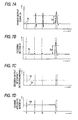
Figs. 7A to 7D are charts for explaining the operation
and function of the contact detecting means by the cord-shaped
pressure sensitive sensor 10, Fig. 7A being a characteristic
chart showing an output signal VS of the cord-shaped pressure
sensitive sensor 10, Fig. 78 being a characteristic chart showing
an output signal Vf of the filtering section 27a, Fig. 7C being
a characteristic chart showing a decision output J of the contact
detecting means 27, and Fig. 7D being a characteristic chart
showing a voltage Vm applied to the motor 23a. An axis of abscissa
indicates a time t in common to all the charts.
-
Description will be given to the behaviors of the output
signal VS of the cord-shaped pressure sensitive sensor 10, the
output signal Vf of the filtering section 27a, the decision output
J of the contact detecting means 27 and the voltage Vm applied
to the motor 23a respectively in the case in which the running
device 20 passes through a step and then comes in contact with
an obstacle.
-
First of all, when a voltage of +Vd is applied to the motor
23a by the control means 27 at a time t1, the running device
20 starts running. During the running, the cord-shaped pressure
sensitive sensor 10 is oscillated due to the running oscillation
of the running device 20, and a signal corresponding to the
acceleration of the deformation of the cord-shaped pressure
sensitive sensor 10 shown in Fig. 7Ais output from the cord-shaped
pressure sensitive sensor 10 by piezoelectric effects. More
specifically, a fine fluctuation component is superposed on a
reference potential V0 for VS.
-
In Fig. 7A, a signal exceeding a predetermined great
amplitude D0 is generated when the running device 20 runs on
a step at a time t2. When the running device 20 completely passes
through the step at a time t3, a large signal is generated again.
A great oscillation is applied to the cord-shaped pressure
sensitive sensor 10 by an impact caused by running on the step
and completely passing through the step. Consequently, a signal
having a great amplitude is generated for VS.
-
Then, when an obstacle comes in contact with a bumper 25
at a time t4, the cord-shaped pressure sensitive sensor 10 is
deformed by the pressing of the obstacle so that a signal having
a great amplitude is generated for VS.
-
At this time, the output V0 sent from the filtering section
27a filters the output signal of the cord-shaped pressure
sensitive sensor 10 based on the filtering characteristic of
Fig. 6. Therefore, the oscillation frequency component f3
during the running including the natural frequency f0 of the
running device 20 is removed as shown in Fig. 7B, and furthermore,
the low oscillation component of f1 generated when the running
device 20 runs on the step is also removed. Finally, only a
frequency component indicated as f2 in Fig. 6 which is generated
by a contact with an obstacle is caused to pass.
-
At time of the contact with the obstacle, the cord-shaped
pressure sensitive sensor 10 is slightly deformed in the contact
if the cord-shaped pressure sensitive sensor 10 is simply
provided in the bumper 25. In the embodiment, however, the
cord-shaped pressure sensitive sensor 10 is provided through
an elastic fixing member 30 as shown in Fig. 5 and can be deformed
together with the elastic fixing member 30 at time of the contact
with the obstacle. Consequently, the amount of the deformation
of the cord-shaped pressure sensitive sensor 10 is increased.
Since the hollow section 35 is also crushed at time of the contact,
the amount of the deformation of the cord-shaped pressure
sensitive sensor 10 is further increased. Thus, a large amount
of the deformation of the cord-shaped pressure sensitive sensor
10 can be obtained and an acceleration to be the secondary
differential value of the amount of the deformation is also
increased. As a result, the output signal of the cord-shaped
pressure sensitive sensor 10 is also increased so that the
detection sensitivity of the obstacle can be enhanced.
-
The contact detecting section 27b decides that the obstacle
comes in contact if an amplitude |V - V0| from V0 for Vf is greater
than D0, and outputs a pulse signal of Lo → Hi → Lo as a decision
output at the time t4. Even if an amplitude |V - V0| from V0
for VS is greater than D0, thus, a contact decision is carried
out based on the signal Vf from which an unnecessary frequency
component is removed by the filtering section 27a. Therefore,
erroneous detection can be prevented from being caused by a
running oscillation.
-
The control means 28 (Fig. 4) stops the application of
a voltage of +Vd to the motor 23a if the pulse signal is generated.
Consequently, the running operation of the running device 20
is stopped at the time t4. D0 can be set optionally and is preset
based on the magnitude of the output signal of the cord-shaped
pressure sensitive sensor 10 at time of the contact of the obstacle
depending on a running speed or the shape of the elastic fixing
member 30, for example.
-
Moreover, the cord-shaped pressure sensitive sensor 10
is a contactless sensor and an output signal corresponding to
the acceleration of deformation is generated as described above.
Even if a piezoelectric sensor is provided along a corner section
25a of the running device 20, therefore, erroneous detection
in a conventional structure using a tape switch is not generated.
-
Furthermore, the tape switch is not used differently from
the conventional art. Therefore, an insertion hole does not
need to be provided in the corner section 25a of the running
device 20, and a great deal of time and labor is not required
for manufacture and an appearance can also be enhanced.
-
As described above, in the embodiment, the cord-shaped
pressure sensitive sensor 10 having a flexibility which can be
provided around a mobile running device body and the contact
detecting means 27 for detecting that the running device 20 comes
in contact with an obstacle based on the output signal of the
cord-shaped pressure sensitive sensor 10 are added, and the
contact detecting means 27 includes the filtering section 27a
for removing an oscillation frequency component during the
running operation of the running device 20 from the output signal
of the cord-shaped pressure sensitive sensor 10. Consequently,
the cord-shaped pressure sensitive sensor 10 is a contactless
sensor and generates an output signal corresponding to the
acceleration of deformation. Thus, it is possible to implement
a contact detecting device which can prevent error detection
even if the cord-shaped pressure sensitive sensor 10 is provided
along the corner section 25a of the running device 20.
-
Furthermore, since the filtering section 27a removes an
oscillation frequency component during the running operation
of the running device 20 from the output signal of the cord-shaped
pressure sensitive sensor 10, the contact detecting means 27
can prevent erroneous detection by an oscillation during running.
-
Moreover, the contact detecting device described above
is provided and the control means 28 for controlling running
based on the output signal of the contact detecting device is
provided. Consequently, the insertion hole 85b does not need
to be provided on the corner section 25a of the running device
differently from the conventional art. Thus, a great deal of
time and labor is not required for manufacture and an appearance
can also be enhanced.
-
Furthermore, the filtering section 27b removes an
oscillation frequency component during the running operation
of the running device 20 from the output signal of the cord-shaped
pressure sensitive sensor 10. Therefore, it is possible to
prevent an erroneous operation in which the contact detecting
means 27 carries out erroneous detection due to an oscillation
during running, thereby stopping the running.
-
Moreover, the filtering section 27b has such a structure
as to remove a frequency component including the natural
frequency of the running device 20. By checking the natural
frequency of the running device 20, therefore, it is possible
to easily determine the filtering characteristic of the filtering
section.
-
While the elastic fixing member 30 is fixed to the bumper
25 in the embodiment, the bumper 25 may also serve as the elastic
fixing member 30. By this structure, the bumper 25 also serves
as the elastic fixing member 30. Consequently, components can
be rationalized.
-
As shown in Fig. 3, furthermore, a dimension L of the elastic
fixing member 30 is set to be greater than a distance at which
the running device 20 runs while the contact detecting means
27 detects a contact with an obstacle and the control means 28
then controls to stop the running. Even if the obstacle comes
in contact with and presses the running device 20, therefore,
the running device 20 is stopped before the elastic fixing member
30 is completely crushed. Consequently, an excessive load is
not applied to the obstacle and the running device 20 so that
safety can be enhanced.
-
Moreover, it is also possible to employ a structure in
which the running is controlled such that a movement is once
carried out in an opposite direction to a running direction and
running is then carried out in an original running direction
when running is started in a stop condition. By this structure,
even if an obstacle has already come in contact with the running
device 20 in the running direction in the stop condition and
the cord-shaped pressure sensitive sensor 10 cannot be deformed
any longer, the movement is carried out in the opposite direction
to the running direction and the deformation of the cord-shaped
pressure sensitive sensor 10 is released, and the cord-shaped
pressure sensitive sensor 10 is deformed again in contact with
the obstacle at time of running in the original running direction
so that the contact with the obstacle is detected by the contact
detecting means 27. Consequently, the safety can further be
enhanced.
(Second Embodiment)
-
Next, a second embodiment of the invention will be
described with reference to Fig. 5B.
-
Fig. 5B is a sectional view showing a bumper sensor unit
14 of a running device according to a second embodiment of the
invention (corresponding to an A - A line in Fig. 3B).
-
The second embodiment is different from the structure
according to the first embodiment in that a cord-shaped pressure
sensitive sensor 10 is attached to a bumper 25 through an elastic
fixing member 30 having a different oscillation characteristic
from the natural oscillation characteristic of the running device
20 (Figs. 3A and 3B).
-
Components other than those described above are the same
as in the first embodiment and detailed description will be
omitted.
-
In order to cause the elastic fixing member 30 to have
a different oscillation characteristic from the natural
oscillation characteristic of the running device 20, for example,
a different material of a partial space 40 in the elastic fixing
member 30 is inserted or an air layer is provided to carry out
a trial experiment.
-
By the structure described above, the elastic fixing member
30 removes an oscillation during running which is propagated
from the running device 20 and a noise is not applied to the
cord-shaped pressure sensitive sensor 10. Consequently,
contact detecting means 27 (in this case, Fig. 4A is available)
can prevent erroneous detection by the oscillation during the
running.
-
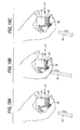
Figs. 8A to 8C are views illustrating the elastic fixing
member 30 having a different oscillation characteristic from
the natural oscillation characteristic of the running device
20.
-
In Figs. 8A to 8C, 30 denotes the elastic fixing member
enclosing the cord-shaped pressure sensitive sensor 10, and a
gap 35 is provided between an attachment portion (shown in
hatching) and the cord-shaped pressure sensitive sensor 10. Fig.
8A shows a small gap 35', Fig. 8B shows a greater gap 35" and
Fig. 8C shows a maximum gap 35'".
-
Since the elastic fixing member 30 in Fig. 8A is firm,
the sensitivity of the cord-shaped pressure sensitive sensor
10 is reduced.
-
To the contrary, since the elastic fixing member 30 in
Fig. 8C is not firm, the sensitivity is increased and resonance
with the ordinary idling of a vehicle is detected erroneously.
-
The elastic fixing member 30 shown in Fig. 8B is
intermediate between those shown in Figs 8A and 8C and is set
within a range employed in the second embodiment. The specific
size of the gap 35 is determined depending on the natural
oscillation characteristic of the running device 20.
-
According to the second embodiment, thus, the elastic
fixing member 30 removes an oscillation during running which
is propagated from the running device 20. Therefore, the
oscillation during the running can be prevented from being
detected erroneously.
-
By using the first embodiment together, furthermore, an
excessive impact is applied to the running device 20 during the
running and the filtering section 27a in Fig. 4B removes an
oscillation frequency component during the running operation
of the running device 20 from the output signal of the cord-shaped
pressure sensitive sensor 10 even if the elastic fixing member
30 cannot completely attenuate the oscillation caused by the
impact. Consequently, the contact detecting means 27 can be
prevented from erroneously detecting the oscillation during the
running. Thus, an advantage can be obtained more reliably.
-
While the contact detecting device and the running device
are applied to an automated guided vehicle for carrying a baggage
in the first and second embodiments, they may be applied to a
mobile body such as a vehicle, a kart or a toy and a piezoelectric
sensor can be provided in conformity with various shapes of the
mobile bodies to detect an obstacle.
-
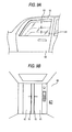
As shown in Figs. 9A and 9B, furthermore, the contact
detecting device and the running device can also be applied to
a cord-shaped pressure sensitive sensor provided in a place in
which a part of a human body is not desired to be pinched. Fig.
9A shows an example in which they are applied to the power window
of a vehicle and Fig. 9B shows an example in which they are applied
to the automatic door of an elevator.
-
In Fig. 9A, 50 denotes a door of a vehicle, and a windowpane
51 ascends gradually and is accommodated in a door frame 52.
In this case, if the cord-shaped pressure sensitive sensor 10
is provided in the door frame 52, the windowpane 51 ascends even
though the hand or finger of a child touches the windowpane 51.
Consequently, the cord-shaped pressure sensitive sensor 10
detects the hand or finger before touching the door frame 52.
Thus, the windowpane 51 can be stopped ascending and a motor
can be rotated reversely to quickly release the hand or finger
from the touch between the windowpane 51 and the door frame 52.
Details of this embodiment will be discussed later.
-
In such a device, in the case in which a door on the passenger
seat side is banged when the windowpane 51 is ascending with
the door 50 on the driver side of the vehicle closed, the
cord-shaped pressure sensitive sensor 10 of the door 50 on the
driver side of the vehicle detects an impact oscillation so that
the windowpane 51 'is stopped ascending and the motor is rotated
reversely.
-
Also in this case, however, if the first and second
embodiments of the invention are employed, there is no problem.
More specifically, even if the cord-shaped pressure sensitive
sensor 10 of the door 50 on the driver side of the vehicle detects
an impact oscillation generated by banging the door on the
passenger seat side when the windowpane 51 is ascending with
the door 50 on the driver side of the vehicle closed, the impact
oscillation is disregarded by the filtering section 27b according
to the first embodiment and/or the elastic fixing member 30
according to the second embodiment which has a different
oscillation characteristic from the natural oscillation
characteristic of the vehicle and the windowpane 51 can be caused
to continuously ascend without erroneous detection. According
to the invention, therefore, it is possible to prevent such an
unnecessary malfunction. While the invention is applied to the
power window of a vehicle in the embodiment, it may be applied
to an electrically operated slide door, an electrically operated
sunroof, a power hatch door and an electrically operated trunk.
-
In Fig. 9B, next, 60 denotes an elevator, 61 denotes an
automatic door, and 10 denotes a cord-shaped pressure sensitive
sensor provided on the tip of the automatic door 61.
-
In Fig. 9B, even if a part of a human body and clothes
are apt to be pinched in the automatic door 61 when the automatic
door 61 of the elevator 60 is closed, the cord-shaped pressure
sensitive sensor 10 detects the pinching in advance.
Consequently, the closing operation of the automatic door 61
is stopped and the motor is rotated reversely to start an opening
operation again. Thus, a part of the human body and the clothes
can be released quickly.
-
In such a device, in the case in which a great impact
oscillation is generated on the inside or outside of the elevator
60 when the automatic door 61 of the elevator 60 is closed, the
cord-shaped pressure sensitive sensor 10 detects the same impact
oscillation sensitively. Consequently, the closing operation
of the automatic door 61 is stopped and the motor is rotated
reversely so that the opening operation is started again.
-
By employing the first and second embodiments of the
invention, however, even if a great impact oscillation is
generated on the inside or outside of the elevator 60 and the
cord-shaped pressure sensitive sensor 10 detects the impact
oscillation sensitively when the automatic door 61 of the
elevator 60 is being closed, the impact oscillation is
disregarded by the filtering section 27b according to the first
embodiment and/or the elastic fixing member 30 according to the
second embodiment which has a different oscillation
characteristic from the natural oscillation characteristic of
the elevator 60 and the closing operation of the automatic door
61 is carried out continuously without erroneous detection.
According to the invention, therefore, such an unnecessary
malfunction can be prevented.
-
In addition, the invention can prevent such an unnecessary
malfunction that a great impulsive sound having a low frequency
is sensed to start the opening operation again in the middle
of the closing operation of the automatic door also in an
automatic door provided in the entrance of a department store,
a supermarket or a convenience store in which the cord-shaped
pressure sensitive sensor 10 is provided (this malfunction may
be caused in respect of fail-safe.
-
In all of the above examples, moreover, the cord-shaped
pressure sensitive sensor 10 is provided in a moving thing or
is provided in an opposite position to the moving thing. Also
in other cases, it is a matter of course that the invention can
be applied. For example, in case of security (invasion
detection) in which the cord-shaped pressure sensitive sensor
10 is provided on a wall or fence in a site, the invention can
be applied. When a part of the human body, clothes and tools
of an invader touch the cord-shaped pressure sensitive sensor
10 provided on the wall or fence in the site, the cord-shaped
pressure sensitive sensor 10 detects the touch to inform a
resident in the site by means of a burglar alarm.
-
Also in this case, the cord-shaped pressure sensitive
sensor 10 carries out erroneous detection to operate the burglar
alarm by an oscillation generated when a vehicle passes through
the neighborhood. According to the invention, however, these
oscillations can be prevented from being detected erroneously.
Consequently, the burglar alarm can be prevented from being
operated erroneously.
(Third Embodiment)
-
Fig. 11 is a view showing the appearance of an object
detecting device 100 comprising a pressure sensitive sensor and
an opening and closing device 150 according to the invention,
illustrating an example of the case in which they are applied
to the power window of a car. Fig. 12 is a view showing the
structure of an A - A section in Fig. 11. In Fig. 12 , the right
side indicates an inside of a vehicle compartment and the left
side indicates an outside of the vehicle compartment.
-
First of all, the basic structure of the object detecting
device 100 according to the embodiment is as follows. In Fig.
11, 11 denotes a door of a car, 13 denotes a window frame to
be an opening section, and 15 denotes a windowpane to be an opening
and closing section. 17 denotes a pressure sensitive sensor
which is provided on the peripheral edge of the end of the window
frame 13. 19 denotes deciding means for deciding a contact of
an object with the pressure sensitive sensor 17 based on the
output signal of'the pressure sensitive sensor 17.
-
Moreover, the switchgear 150 according to the embodiment
is constituted by the object detecting device 100, driving means
21 for opening and closing the windowpane 15, and control means
23 for controlling the driving means 21. The driving means 21
is constituted by a motor 25, a wire 27, a support tool 29 for
the windowpane 15, and a guide 31. The wire 27 is moved by the
motor 25, and the support tool 29 coupled to the wire 27 is
vertically moved along the guide 31 so that the windowpane 15
is opened and closed. The driving means 21 is not restricted
to a method using the wire 27 described above but may employ
another method. Moreover, the control means 23 maybe integrated
with the motor 25.
-
As shown in Fig. 12, the pressure sensitive sensor 17
according to the embodiment comprises a flexible piezoelectric
sensor 33 to be pressure sensitive means, and support means 35.
The support means 35 comprises a first deformation section 37
having the piezoelectric sensor 33 provided in the vicinity of
a lowermost portion and formed of an elastic member such as rubber
or a foamed resin member, and a second deformation section 39
bonded to the first deformation section 37 and fixed to the window
frame 13. More specifically, the first deformation section 37
has a follow section 41 and a side wall section 43, and a macro
elastic modulus obtained by integrating the hollow section 41
and the side wall section 43 is represented by E1 (a first elastic
modulus). On the other hand, a macro elastic modulus of the
second deformation section 39 is represented by E2 (a second
elastic modulus) which is greater than E1. In other words, in
the first deformation section 37, the thickness of the support
means 35 provided around the piezoelectric sensor 33 is reduced
such that the piezoelectric sensor 33 can easily be deformed,
and the deformation of the piezoelectric sensor 33 is increased.
Moreover, the second deformation section 39 sets the macro
elastic modulus E2 to be greater than the elastic modulus E1
of the first deformation section, thereby obtaining the behavior
of the deformation of the support means 35 in which the first
deformation section 37 is crushed and the second deformation
section 39 is then crushed. The second deformation section 39
is integrated with a weather strip provided in the window frame
13. The support means 35 is not restricted to a two-stage
structure but a third deformation section may be further
provided.
-
Moreover, thermoplastic elastomer (TPE) can be applied
to the first deformation section 37 and ethylene propylene rubber
(EPDM) can be applied to the second deformation section 39, for
example.
-
Furthermore, the pressure sensitive sensor 17 is not
restricted to the opening section side but may be provided on
the opening and closing side.
-
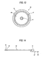
Fig. 13 is a view showing the structure of the section
of the piezoelectric sensor 33. The piezoelectric sensor 33
has such a structure that a center electrode 45 to be an electrode
for leading a signal, a ground electrode 47, a compound
piezoelectric layer 49 formed by a compound piezoelectric member
mixing the sintered powder of piezoelectric ceramic with a rubber
elastic member formed of chlorinated polyethylene, and a covering
layer 51 are laminated concentrically, are molded like a cable
and are polarized, and has a high flexibility and generates an
output signal corresponding to deformation. The sintered
powder of lead titanate or lead zirconate titanate is used for
the piezoelectric ceramic, for example. The piezoelectric
sensor 33 is manufactured in the following procedure. First
of all, a chlorinated polyethylene sheet and piezoelectric
ceramic having (40 to 70) vol% (lead zirconate titanate) powder
are uniformly mixed like a sheet by a roll method. The sheet
is cut into small pellet-shaped pieces, and the pellets are
extruded continuously together with the center electrode 45,
thereby forming the compound piezoelectric layer 49. Then, the
ground electrode 47 is wound around the compound piezoelectric
layer 49. The covering layer 51 is also extruded continuously
to surround the ground electrode 47. Finally, a high DC voltage
of (5 to 10) kV/mm is applied between the center electrode 45
and the ground electrode 47 in order to polarize the compound
piezoelectric layer 49.
-
When the piezoelectric ceramic powder is to be added to
the chlorinated polyethylene, it is preferable that the
piezoelectric ceramic powder should be previously immersed in
a solution of a titanium and coupling agent and should be dried.
By this treatment, the surface of the piezoelectric ceramic
powder is covered with a hydrophilic group and a hydrophobic
group which are contained in the titanium and coupling agent.
The hydrophilic group prevents the coagulation of the
piezoelectric ceramic powder, and furthermore, the hydrophobic
group increases a wettability of the chlorinated polyethylene
and the piezoelectric ceramic powder. As a result, the
piezoelectric ceramic powder can be uniformly added in a large
amount up to 70 vol% at a maximum in the chlorinated polyethylene.
It has been found that the same effects can be obtained by adding
the titanium and coupling agent during the rolling of the
chlorinated polyethylene and the piezoelectric ceramic powder
in place of the immersion in the titanium and coupling agent
solution. This treatment is excellent in that the immersion
treatment in the titanium and coupling agent solution is not
specially required. Thus, the chlorinated polyethylene also
plays a part of a binder resin in the mixture of the piezoelectric
ceramic powder.
-
While an ordinary metallic single conductor may be used
for the center electrode 45, an electrode obtained by winding
a metallic coil around an insulating polymeric fiber is used.
Polyester fiber which has been commercially used in an electric
blanket and a copper alloy containing 5 wt% of silver are
preferable for the insulating polymeric fiber and the metallic
coil, respectively.
-
The ground electrode 47 has such a structure that a
band-shaped electrode having a metal film bonded onto a polymer
layer is used and is wound around the compound piezoelectric
layer 49. Since an electrode using polyethylene terephthalate
(PET) as the polymer layer and having an aluminum film bonded
thereto has a high thermal stability at 120□ and is also
mass-produced commercially, it is preferable for the ground
electrode 47. The electrode can be connected to the deciding
means 19 through caulking or holdfast, for example. Moreover,
a metallic single coil or a metallic braided wire may be wound
around the aluminum film of the ground electrode 47 and may be
thus conducted to the aluminum film, and the metallic single
coil or the metallic braided wire may be soldered to the deciding
means 19. Since the soldering can be carried out, the efficiency
of a work can be enhanced. In order to shield the piezoelectric
sensor from the electrical noise of an external environment,
it is preferable that the ground electrode 47 should be wound
around the compound piezoelectric layer 49 with overlapping.
-
While it is preferable that vinyl chloride or polyethylene
should be used for the covering layer 51, an elastic material
such as rubber having a higher flexibility than that of the
compound piezoelectric layer 49 may be used such that the
piezoelectric sensor 33 can be deformed easily in the pressing
of an object. In consideration of a heat resistance and a cold
resistance of vehicle parts, a material is selected. More
specifically, it is preferable that a material having a small
reduction in a flexibility at -30□ to 85□ should be selected.
For such rubber, for example, it is preferable to use
ethylene-propylene rubber (EPDM), chloroprene rubber (CR),
butyl rubber (IIR), silicone rubber (Si) or thermoplastic
elastomer. By the structure described above, the minimum
curvature of the piezoelectric sensor 33 can have a radius of
5 mm at a maximum.
-
As described above, since the compound piezoelectric
member of the piezoelectric sensor 33 has the flexibility of
the chlorinated polyethylene and the high temperature durability
of the piezoelectric ceramic, a sensitivity is not reduced at
a high temperature as in a conventional piezoelectric sensor
using polyvinylidene fluoride as a piezoelectric and a high
temperature durability is great, and furthermore, a vulcanizing
step is not required during molding like rubber such as EPDM.
Consequently, it is possible to obtain an advantage that a
production efficiency is high.
-
Fig. 14 is a view showing the appearance of the
piezoelectric sensor 33, in which a resistor 55 for disconnection
detection is provided in an end 53 of the piezoelectric sensor
33. The resistor 55 for disconnection detection is connected
between the center electrode 45 and the ground electrode 47 in
the piezoelectric sensor 33. The resistor 55 for disconnection
detection also serves as a discharge section for discharging
an electric charge generated in the piezoelectric sensor 33 by
a pyroelectric effect so that components are rationalized. The
piezoelectric sensor 33 is directly connected to the deciding
means 19, and the piezoelectric sensor 33 and the deciding means
19 are thus integrated. Moreover, a cable 57 for supplying a
power and outputting a detection signal and a connector 59 are
connected to the deciding means 19. In the case in which the
piezoelectric sensor 33 is provided in the support means 35,
the resistor 55 for disconnection detection is provided in the
end 53 and the piezoelectric sensor 33 is inserted in the support
means 35, and the piezoelectric sensor 33 and the deciding means
19 are then connected and integrated with each other. At the
same time that the support means 35 is to be molded by extrusion
molding, the piezoelectric sensor 33 may be extruded and provided
in the support means 35 and the resistor 55 for disconnection
detection may be then provided in the end 53, and the piezoelectric
sensor 33 and the deciding means 19 may be thus integrated.
-
Fig. 15 is a block diagram showing the object detecting
device and the opening and closing device according to the
embodiment. The deciding means 19 comprises a resistor 61 for
voltage division which is used for detecting the disconnection
of the pressure sensitive sensor 17, a filtering section 62 for
passing only a predetermined frequency component from an output
signal sent from the piezoelectric sensor 33, a deciding section
63 for deciding the contact of an object with the pressure
sensitive sensor 17 based on an output signal sent from the
filtering section 62, and an abnormality deciding section 64
for deciding the abnormality of the disconnection of the center
electrode 45 and the ground electrode 47 in the piezoelectric
sensor 33 from a voltage value formed by the resistor 55 for
disconnection detection and the resistor 61 for voltage division.
Moreover, a signal input section 65 for connecting the center
electrode 45 and the ground electrode 47 to the deciding means
19 and for inputting a signal output from the piezoelectric sensor
33 to the deciding means 19 and a signal output section 66 for
outputting a decision signal sent from the deciding section 63
are provided adjacently in the deciding means 19. A power line
and a ground line to reach the deciding means 19 are also connected
to the signal output section 66. Furthermore, the deciding means
19 has a bypass section 67 such as a capacitor provided between
the signal input section 65 and the signal output section 66
and serving to bypass a high frequency signal.
-
The driving means 21 has a hole element 68 for detecting
the rotation pulse of the motor 25.
-
The control means 23 comprises a position detecting section
71 for detecting the position of the upper end of the windowpane
15 based on an output signal sent from the hole element 68, an
opening and closing section contact deciding section 72 for
detecting the moving speed of the windowpane 15 based on the
output signal sent from the hole element 68, thereby deciding
the contact of an object with the windowpane 15, and a control
section 73 for controlling the motor 25 based on the output signals
of the deciding means 19, the position detecting section 71 and
the opening and closing section contact deciding section 72.
-
The position detecting section 71 counts and stores a pulse
signal output from the hole element 68, thereby detecting the
current position of the upper end of the windowpane 15. A
position Y of the upper end of the windowpane 15 is represented
by a height from the lowermost point of the window frame 13 as
shown in Fig. 11.
-
The opening and closing section contact deciding section
72 calculates the moving speed of the windowpane 15 from the
pulse separation of a pulse signal output from the hole element
68 based on the fact that the moving speed of the windowpane
15 is reduced when an obj ect comes in contact with the windowpane
15, and decides that the object comes in contact with the
windowpane 15 and outputs a pulse signal of Lo → Hi → Lo if a
change amount |ΔVw| per unit time of the moving speed thus
calculated is greater than a preset value Vw1. Any pulse signal
having an Hi level is set to be a decision signal.
-
Moreover, reporting means 74 for reporting the result of
the decision of the deciding means 19 by means of a predetermined
light provided on a front panel in a vehicle compartment and
an opening and closing switch 75 for opening and closing the
windowpane 15 are connected to the control means 23, and the
opening and closing switch 75 includes an auto-up switch and
an auto-down switch for opening and closing the windowpane 15
by a one-touch operation, and a manual-up switch and a manual-down
switch for opening and closing the windowpane 15 by a manual
operation. There is provided a power supply 76 comprising a
battery of a car which serves to supply a power through the deciding
means 19.
-
The filtering section 62 has such a filtering
characteristic as to remove an unnecessary signal caused by the
vibration of the body of a car from the output signal of the
piezoelectric sensor 33 and to extract only a peculiar frequency
component appearing on the output signal of the piezoelectric
sensor 33 when the piezoelectric sensor 33 is deformed by pressing
due to the contact of an object. In order to determine the
filtering characteristic, it is preferable that the vibration
characteristic of the body of the car or the vibration of the
body during running should be analyzed and optimized.
-
In order to remove an external electrical noise, the
deciding means 19 is wholly covered with a shield member and
is thus shielded electrically. Moreover, the ground electrode
47 is conducted to the shield member of the deciding means 19
and the pressure sensitive sensor 17 is also shielded
electrically. A countermeasure for a high electric field may
be taken by adding a feed-through capacitor or an EMI filter
to the input/output section of the circuit.
-
Next, description will be given to a basic operation for
detecting the contact of an object with the pressure sensitive
sensor 17 by the object detecting device.
-
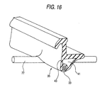
Fig. 16 shows the state of the pressure sensitive sensor
17 in the case in which an object 77 enters and is pinched between
a window frame and a windowpane. When the object 77 comes in
contact with the photosensitive sensor 17, the pressing of the
object 77 is applied to the support means 35 and the piezoelectric
sensor 33. The support means 35 has a more flexibility than
the piezoelectric sensor 33. Therefore, the support means 35
is compressed by the pressing around a point in which the object
77 comes in contact as shown so that the side wall section 43
is deformed and the hollow section 41 is crushed simultaneously.
Consequently, the piezoelectric sensor 33 is also bent and
deformed around a point in which the object 77 comes in contact
with the support means 35. Moreover, also when the window frame
including the pressure sensitive sensor 17 is gripped by hand,
the same deformation is generated in the pressure sensitive
sensor 17.
-
When the piezoelectric sensor 33 is thus deformed, an
output signal corresponding to the deformation is output from
the piezoelectric sensor 33 by a piezoelectric effect. The
signal output from the piezoelectric sensor 33 is filtered by
the filtering section 62. In some cases, an output signal
generated by an unnecessary vibration component caused by the
vibration of the body of a car appears in the output signal of
the piezoelectric sensor 33. The filtering section 62 removes
the unnecessary signal.
-
A procedure for the operations of the deciding section
63 and the control section 73 will be described with reference
to Figs. 17A to 17C. Figs. 17A to 17C are characteristic charts
showing an output signal V sent from the filtering section 62,
a decision output J of the deciding means 19, and a voltage Vm
to be applied to the motor 25. In Figs. 17A to 17C, an axis
of ordinate indicates V, J and Vm from the top and an axis of
abscissa indicates a time t. When the auto-up switch of the
opening and closing switch 75 is turned ON at a time t1, the
control section 73 applies a voltage of +Vd to the motor 25 to
cause the windowpane 15 to carry out a closing operation. The
deciding means 19 carries out a deciding operation during the
closing operation of the windowpane 15. When the object 77 is
pinched as shown in Fig. 16, a signal corresponding to the
acceleration of the deformation of the piezoelectric sensor 33
is output from the piezoelectric sensor 33 by the piezoelectric
effect and a greater signal component than a reference potential
V0 shown in Fig. 17A appears from the filtering section 62. In
this case, with such a structure that the piezoelectric sensor
33 is simply provided in the window frame 13, the piezoelectric
sensor 33 is slightly deformed during pinching. In the
embodiment, the support means 35 has a flexibility as shown in
Fig. 12 and is easily compressed during the pinching so that
the amount of the deformation of the piezoelectric sensor 33
is increased.
-
Since the hollow section 41 is also crushed during the
pinching, the amount of the deformation of the piezoelectric
sensor 33 is further increased. Thus, the large amount of the
deformation can be obtained for the piezoelectric sensor 33 and
an acceleration to be a secondary differential value of the amount
of the deformation is also increased. As a result, the output
signal of the piezoelectric sensor 33 is also increased. The
deciding section 63 decides that a contact with the object 77
is caused if an amplitude of |V - V0| of V from V0 is greater
than D0 (a first change amount) and outputs a pulse signal of
Lo → Hi (a decision signal) → Lo as a decision output at a time
t2 as shown in Fig. 17B.
-
The control section 73 stops the application of a voltage
of +Vd to the motor 25 as shown in Fig. 17C in response to the
decision signal if any and applies a voltage of -Vd for a constant
time till a time t3 to bring down the windowpane 15 in a constant
amount, thereby releasing pinching or preventing the generation
of the pinching. In the case in which a pressure to be applied
to the pressure sensitive sensor 17 is to be released, a signal
corresponding to an acceleration restoring the deformation (a
smaller signal component than the reference potential V0 in Fig.
17A) is output from the piezoelectric sensor 33.
-
In the deformation of the pressure sensitive sensor 17,
the comparison of V with V0 is changed depending on the direction
of bending or polarization of the piezoelectric sensor 33, the
allotment of an electrode (a decision of one of them to be a
reference potential) and the direction of support of the
piezoelectric sensor 33. Since the deciding section 63 decides
the pinching based on the absolute value of the amplitude of
V from V0, the pinching can be decided irrespective of the
comparison of V with V0.
-
In addition to the basic deciding method, it is possible
to prevent the generation of the pinching by deciding the presence
of a contact with an object in the following manner.
-
Figs. 18A and 18B are characteristic charts showing an
output signal V sent from the filtering section 62 and a decision
output J of the deciding means 19. In Figs. 18A and 18B, an
axis of ordinate indicates V and J from the top and an axis of
abscissa indicates a time t.
-
As shown in Fig. 18A, when the pressure sensitive sensor
17 is displaced by gripping the window frame 13 at a time t4,
a signal is output from the piezoelectric sensor 33 by the
piezoelectric effect. As a result, a greater signal component
than the reference potential V0 is generated from the filtering
section 62.
-
In the case in which the output signal V is equal to or
greater than preset V1, that is, the amplitude of |V - V0| of
the output signal V from V0 is greater than V1 (a first change
amount), the deciding section 63 decides that a contact with
the object is caused, and outputs and holds a pulse signal Lo
→ Hi (decision signal) as a decision output at the time t4 as
shown in Fig. 18B. Next, when the window frame 13 is released
to cancel the displacement of the pressure sensitive sensor 17,
a signal is output from the piezoelectric sensor 33 by the same
piezoelectric effect and a smaller signal component than the
reference potential V0 appears from the filtering section 62.
At this time, in the case in which the output signal V is equal
to or smaller than preset V2, that is, the amplitude of |V -
V0| of the output signal V from V0 is greater than V2 (a second
change amount), the deciding section 63 decides that the object
is separated and sets, to Hi → Lo, a pulse signal having an Hi
level to be a decision signal at a time t5. In other words,
the pulse signal is maintained to be Hi and the output of the
decision signal is held while the contact of the object is detected
and the separation is then detected.
-
From the time t4 that the decision signal is output and
the contact of the object is then detected to the time t5 that
the separation of the object is detected, the control section
39 controls to lock the operation of the windowpane 15 even if
the opening and closing switch 75 is operated to bring up or
down the windowpane 15. Consequently, an obstacle is detected
so that the generation of pinching can be prevented, resulting
in an enhancement in safety.
-
The output signal V is changed depending on a polarity
when the piezoelectric sensor 33 is to be polarized. In that
case, the positive and negative signs of a signal shown in the
drawing are reversed. Therefore, it is preferable that the
positive and negative signs of the set values of V1 and V2 should
be reversed.
-
Moreover, it is also possible to have such a structure
that the control means 23 side to be connected can have the function
of the deciding means 19, thereby separating the deciding means
19 from the pressure sensitive sensor 17, resulting in an
enhancement in the management of the installation of the pressure
sensitive sensor 17 itself.
-
Furthermore, in the case in which the contact and
separation of the object is to be detected based on a signal
output from the piezoelectric sensor 33, the structure of the
support means 35 shown in Fig. 25 may be employed.
-
Next, the function of the support means 35 will be
described.
-
In addition to the basic structure, the pressure sensitive
sensor 17 according to the invention has such a structure that
the support means 35 has at least the first deformation section
37 and the second deformation section 39 so that the deformation
can also be detected at time of the application of a static load
and a pressure can be detected more reliably.
-
Figs. 19A to 19C show states in which a pressure is detected
in a compression state, Fig. 19A being an explanatory view showing
the application of a static load, Fig. 19B being an explanatory
view showing a state in which a pressure is further applied,
and Fig. 19C being an explanatory view showing a state in which
a pressure is detected to return a windowpane.
-
As shown in Fig. 19A, a state in which the window frame
13 is gripped is taken as an example in which the pressure sensitive
sensor 17 has already been set in a compression state.
Conventionally, even if a load in a compression direction is
more applied, a displacement generated in the pressure sensitive
sensor 17 is very small. In order to obtain a detection signal
from the piezoelectric sensor 33 on a sufficient output level,
accordingly, it is necessary to use the piezoelectric sensor
33 having a high sensitivity. For this reason, there is a problem
in that a cost is increased. On the other hand, in the pressure
sensitive sensor 17 according to the invention, the first
deformation section 37 is connected to the window frame 13 through
the second deformation section 39. Even if the first deformation
section 37 is completely crushed in an initial state, therefore,
the second deformation section 39 is mainly deformed when a
pressure is further applied by the pressing of the windowpane
15 to bring a state shown in Fig. 19B. Also in the compression
state in which the first deformation section 37 is crushed,
consequently, the piezoelectric sensor 33 is deformed so that
a detection signal can reliably be obtained at a sufficient output
level. When the windowpane 15 is stopped and is started to be
brought down upon receipt of the detection signal from the
piezoelectric sensor 33 as described above, the original state
of Fig. 19A is set again as shown in Fig. 19C.
-
Fig. 20 shows a graph representing the deformation
characteristics of the first deformation section 37 and the
second deformation section 39. In other words, the pressure
sensitive sensor 17 is accommodated in the support means 35 having
a plurality of (two in the embodiment) deformation
characteristics. In the initial deformation of the pressure
sensitive sensor 17 in which the whole window frame 13 is gripped,
the first deformation section 37 having a small macro elastic
modulus (E1) is mainly deformed correspondingly. After a
compression state having a constant level is brought, the second
deformation section 39 having a great macro elastic modulus (E2)
is deformed mainly. By constituting the support means 35 to
have a deformation behavior in a plurality of stages, a detection
signal having a sufficient level for detection can be obtained
from the piezoelectric sensor 33 even if the pressure sensitive
sensor 17 is put under a stress.
-
In addition to the state in which the static load is applied
and the first deformation section 37 is thus crushed, moreover,
the second deformation section 39 is deformed also when a dynamic
load such as a vibration is applied. Consequently, the applied
pressure can be detected reliably at a low cost.
-
Next, a variant of the support means having the deformation
characteristics will be sequentially described below. The same
members as those shown in Fig. 12 have the same reference numerals
and description thereof will be omitted.
-
Fig. 21 is a sectional view showing a first variant in
which the second deformation section is constituted separately
from the weather strip.
-
A first deformation section 37 according to the variant
is formed separately from a weather strip 81 and is bonded to
a second deformation section 83 fixed to a window frame 13. The
second deformation section 83 is formed by a material having
a greater elastic modulus E2 than a macro elastic modulus E1
of the first deformation section 37. For example, the second
deformation section 83 may be formed of harder rubber than the
first deformation section 37.
-
Thus, the second deformation section 83 is formed
separately from the weather strip 81. Consequently, the degree
of freedom of the design of the weather strip 81 can be enhanced,
and furthermore, the bonding to the first deformation section
37 is eliminated so that the degree of freedom of material
selection can also be enhanced.
-
Next, a second variant of the support means will be
described.
-
Fig. 22 is a sectional view showing a structure according
to the second variant in which a second deformation section is
integrated with a first deformation section.
-
In the variant, a first deformation section 37 and a second
deformation section 85 are formed integrally, and the second
deformation section 85 has a gap 87 which is smaller than a hollow
section 41 of the first deformation section 37. The gap 87 may
comprise a plurality of bubbles shown in the drawing and a
plurality of very small hollow sections may be formed. By the
gap 87, the first deformation section 37 is crushed and the second
deformation section 85 is then deformed. Thus, a pressure can
be detected stably under a compressive stress. According to
such a structure, moreover, the first deformation section and
the second deformation section can be processed by integral
molding. Consequently, a manufacturing process and an
assembling process can be simplified.
-
Next, a third variant of the support means will be
described.
-
Fig. 23 is a sectional view showing a structure according
to the third variant in which a second deformation section and
a first deformation section are integrated.
-
In the variant, a first deformation section 37 and a second
deformation section 89 are formed integrally and the second
deformation section 89 has a great thickness such that a distance
L from a window frame 13 on the fixing side of support means
35 has a predetermined value or more. By the distance L, the
first deformation section 37 is crushed and the second
deformation section 89 is then deformed by its own elasticity.
Consequently, a pressure can be detected stably under a
compressive stress. Conventionally, the amount of the
deformation of the second deformation section 89 is very small
because the distance L is short. Consequently, a sufficient
deformation margin cannot be taken. By increasing the distance
L, however, the piezoelectric sensor 33 can easily be deformed
and a pressure can be detected stably. Moreover, the first
deformation section 37 and the second deformation section 89
can readily be molded integrally.
-
In addition to the structure according to each of the
variants, the following structure can also be employed. More
specifically, as shown in Fig. 24A, in the case in which an object
77 presses the pressure sensitive sensor 17 during the closing
operation of a windowpane, the pressure sensitive sensor 17 does
not detect that the windowpane 15 is pressed against the object
77 when the window frame 13 has a high rigidity. By setting
the rigidity of the window frame 13 to be lower by a predetermined
amount, however, the window frame 13 is elastically deformed
and flexed when the windowpane 15 is pressed against the object
77 as shown in Fig. 24B. By the flexure, a detection signal
having a sufficient output level can be obtained from the
piezoelectric sensor. More specifically, the window frame 13
has the function of the second deformation section.
-
According to the pressure sensitive sensor, the object
detecting device and the opening and closing device described
above, the processing of a signal sent from the piezoelectric
sensor is varied or the shape of the support means is changed.
Consequently, a detection capability can be enhanced at a low
cost. In other words, also in the case in which external force
is suddenly applied to the pressure sensitive sensor, a time
taken from the start of a contact to the end thereof is recognized
based on a signal output from the piezoelectric sensor and a
driving operation for this period can be locked. Also in the
case in which external force is applied under a static pressure
in which a pressure is preloaded to the pressure sensitive sensor,
moreover, the second deformation section of the support member
is deformed so that a signal having a sufficient output level
can be obtained from the piezoelectric sensor and reliable
detection can be carried out. By these effects, an obstacle
can be detected reliably to prevent pinching so that stability
can be enhanced still more.
-
Moreover, the invention is not restricted to a pressure
sensitive sensor to be provided in the window frame of a car
but can also be applied to the slide door of the side surface
of a body in a car, an electrically operated sunroof provided
on the ceiling of the body, an electrically operated hatch door
in the rear part of the body or an electrically operated trunk,
for example, and the same advantages as those described above
can be obtained. Furthermore, the invention is not restricted
to the car but can also be applied to an automatic door of a
train or a building.
-
According to the invention, an object can be detected
stably with high precision at a low cost in any situation by
using the piezoelectric sensor for detecting an acceleration
component, can enhance the effect of detecting an obstacle and
preventing pinching, and can improve safety still more.
-
As described above, according to the contact detecting
device of the invention comprising a cord-shaped pressure
sensitive sensor provided on a contact detecting object and
contact detecting means for detecting a contact of a thing with
the contact detecting object based on a signal output from the
cord-shaped pressure sensitive sensor, the contact detecting
means includes a filtering section for removing an oscillation
frequency component of the contact detecting object from the
signal output from the cord-shaped pressure sensitive sensor.
Therefore, the cord-shaped pressure sensitive sensor generates
the output signal corresponding to the acceleration of
deformation. Even if the piezoelectric sensor is provided along
the corner section of a running device, therefore, error
detection can be prevented. In addition, an oscillation during
the running operation of the running device can be prevented
from being picked up by the filtering section for removing the
oscillation frequency component of the contact detecting object
so that the erroneous detection can be prevented.
-
According to the contact detecting device in accordance
with the second aspect of the invention, in the contact detecting
device according to the first aspect of the invention, the
filtering section serves to remove a frequency component
including a natural frequency of the contact detecting object.
By checking the natural frequency of the contact detecting object,
therefore, it is possible to easily determine the filtering
characteristic of the filtering section.
-
According to the contact detecting device in accordance
with the third aspect of the invention comprising a cord-shaped
pressure sensitive sensor provided on a contact detecting object
and contact detecting means for detecting a contact of a thing
with the contact detecting object based on a signal output from
the cord-shaped pressure sensitive sensor, the cord-shaped
pressure sensitive sensor is provided on the contact detecting
object through support means having a different oscillation
characteristic from a natural oscillation characteristic of the
contact detecting object. Therefore, the cord-shaped pressure
sensitive sensor generates the output signal corresponding to
the acceleration of deformation. Even if the piezoelectric
sensor is provided along the corner section of a running device,
therefore, error detection can be prevented. In addition, an
oscillation during the running operation of the running device
can be prevented from being picked up by the support means having
a different oscillation characteristic from the natural
oscillation characteristic so that the erroneous detection can
be prevented.
-
According to the contact detecting device in accordance
with the fourth aspect of the invention, in the contact detecting
device according to the first or second aspect of the invention,
the cord-shaped pressure sensitive sensor is provided on the
contact detecting object through support means having a different
oscillation characteristic from a natural oscillation
characteristic of the contact detecting object. Therefore, the
double countermeasures are taken so that it is possible to more
reliably prevent the erroneous detection in which the oscillation
during the running operation of the running device is picked
up.
-
According to the contact detecting device in accordance
with the fifth aspect of the invention, in the contact detecting
device according to any of the first to fourth aspects of the
invention, the contact detecting object includes an automated
guided vehicle or a bumper of a vehicle, a security object, a
power window of a vehicle, or an automatic door of an elevator
or a house entrance. Moreover, according to the automated guided
vehicle, the vehicle, the security object or the elevator in
accordance with the sixth aspect of the invention, there are
provided the contact detecting device according to any of the
first to fourth aspects of the invention and control means for
controlling opening and closing means based on a signal output
from the contact detecting device. Consequently, the automated
guided vehicle or the bumper of a vehicle, the security object
or the power window of a vehicle, or the automatic door of an
elevator or a house entrance can be prevented from malfunctioning
due to a noise other than original detection.