EP1431039A1 - Start-up and shut down of continuous inkjet print head - Google Patents
Start-up and shut down of continuous inkjet print head Download PDFInfo
- Publication number
- EP1431039A1 EP1431039A1 EP03078837A EP03078837A EP1431039A1 EP 1431039 A1 EP1431039 A1 EP 1431039A1 EP 03078837 A EP03078837 A EP 03078837A EP 03078837 A EP03078837 A EP 03078837A EP 1431039 A1 EP1431039 A1 EP 1431039A1
- Authority
- EP
- European Patent Office
- Prior art keywords
- ink
- porous
- nozzles
- fluid
- porous element
- Prior art date
- Legal status (The legal status is an assumption and is not a legal conclusion. Google has not performed a legal analysis and makes no representation as to the accuracy of the status listed.)
- Granted
Links
- 239000012530 fluid Substances 0.000 claims abstract description 68
- 238000004140 cleaning Methods 0.000 claims abstract description 21
- 238000004891 communication Methods 0.000 claims abstract description 8
- 230000001052 transient effect Effects 0.000 claims abstract description 4
- 238000000034 method Methods 0.000 claims description 16
- 238000007641 inkjet printing Methods 0.000 claims description 6
- 238000010521 absorption reaction Methods 0.000 claims description 4
- 230000015572 biosynthetic process Effects 0.000 claims description 3
- 238000009825 accumulation Methods 0.000 claims description 2
- 230000004044 response Effects 0.000 claims description 2
- 230000003247 decreasing effect Effects 0.000 claims 2
- 230000000903 blocking effect Effects 0.000 claims 1
- 230000004888 barrier function Effects 0.000 abstract description 2
- 239000000976 ink Substances 0.000 description 117
- ORQBXQOJMQIAOY-UHFFFAOYSA-N nobelium Chemical compound [No] ORQBXQOJMQIAOY-UHFFFAOYSA-N 0.000 description 27
- 238000007639 printing Methods 0.000 description 23
- 239000007789 gas Substances 0.000 description 16
- 239000011324 bead Substances 0.000 description 7
- 238000011084 recovery Methods 0.000 description 5
- 238000000926 separation method Methods 0.000 description 4
- 238000004519 manufacturing process Methods 0.000 description 3
- IJGRMHOSHXDMSA-UHFFFAOYSA-N Atomic nitrogen Chemical compound N#N IJGRMHOSHXDMSA-UHFFFAOYSA-N 0.000 description 2
- XUIMIQQOPSSXEZ-UHFFFAOYSA-N Silicon Chemical compound [Si] XUIMIQQOPSSXEZ-UHFFFAOYSA-N 0.000 description 2
- 230000008021 deposition Effects 0.000 description 2
- 230000000694 effects Effects 0.000 description 2
- 238000005516 engineering process Methods 0.000 description 2
- 239000000463 material Substances 0.000 description 2
- 230000007246 mechanism Effects 0.000 description 2
- 239000002245 particle Substances 0.000 description 2
- 229910052710 silicon Inorganic materials 0.000 description 2
- 239000010703 silicon Substances 0.000 description 2
- 230000007704 transition Effects 0.000 description 2
- XLYOFNOQVPJJNP-UHFFFAOYSA-N water Substances O XLYOFNOQVPJJNP-UHFFFAOYSA-N 0.000 description 2
- 230000009471 action Effects 0.000 description 1
- 230000004913 activation Effects 0.000 description 1
- 230000002411 adverse Effects 0.000 description 1
- PNEYBMLMFCGWSK-UHFFFAOYSA-N aluminium oxide Inorganic materials [O-2].[O-2].[O-2].[Al+3].[Al+3] PNEYBMLMFCGWSK-UHFFFAOYSA-N 0.000 description 1
- 239000004020 conductor Substances 0.000 description 1
- 230000001276 controlling effect Effects 0.000 description 1
- 229910052593 corundum Inorganic materials 0.000 description 1
- 238000009826 distribution Methods 0.000 description 1
- 230000005284 excitation Effects 0.000 description 1
- 238000001914 filtration Methods 0.000 description 1
- 230000002209 hydrophobic effect Effects 0.000 description 1
- 239000007788 liquid Substances 0.000 description 1
- 238000012423 maintenance Methods 0.000 description 1
- 230000004048 modification Effects 0.000 description 1
- 238000012986 modification Methods 0.000 description 1
- 229910052757 nitrogen Inorganic materials 0.000 description 1
- 230000000737 periodic effect Effects 0.000 description 1
- 239000011148 porous material Substances 0.000 description 1
- 230000001105 regulatory effect Effects 0.000 description 1
- 239000004065 semiconductor Substances 0.000 description 1
- 239000007921 spray Substances 0.000 description 1
- 229910001845 yogo sapphire Inorganic materials 0.000 description 1
Images



Classifications
-
- B—PERFORMING OPERATIONS; TRANSPORTING
- B41—PRINTING; LINING MACHINES; TYPEWRITERS; STAMPS
- B41J—TYPEWRITERS; SELECTIVE PRINTING MECHANISMS, i.e. MECHANISMS PRINTING OTHERWISE THAN FROM A FORME; CORRECTION OF TYPOGRAPHICAL ERRORS
- B41J2/00—Typewriters or selective printing mechanisms characterised by the printing or marking process for which they are designed
- B41J2/005—Typewriters or selective printing mechanisms characterised by the printing or marking process for which they are designed characterised by bringing liquid or particles selectively into contact with a printing material
- B41J2/01—Ink jet
- B41J2/07—Ink jet characterised by jet control
- B41J2/075—Ink jet characterised by jet control for many-valued deflection
- B41J2/08—Ink jet characterised by jet control for many-valued deflection charge-control type
- B41J2/09—Deflection means
-
- B—PERFORMING OPERATIONS; TRANSPORTING
- B41—PRINTING; LINING MACHINES; TYPEWRITERS; STAMPS
- B41J—TYPEWRITERS; SELECTIVE PRINTING MECHANISMS, i.e. MECHANISMS PRINTING OTHERWISE THAN FROM A FORME; CORRECTION OF TYPOGRAPHICAL ERRORS
- B41J2/00—Typewriters or selective printing mechanisms characterised by the printing or marking process for which they are designed
- B41J2/005—Typewriters or selective printing mechanisms characterised by the printing or marking process for which they are designed characterised by bringing liquid or particles selectively into contact with a printing material
- B41J2/01—Ink jet
- B41J2/07—Ink jet characterised by jet control
- B41J2/105—Ink jet characterised by jet control for binary-valued deflection
-
- B—PERFORMING OPERATIONS; TRANSPORTING
- B41—PRINTING; LINING MACHINES; TYPEWRITERS; STAMPS
- B41J—TYPEWRITERS; SELECTIVE PRINTING MECHANISMS, i.e. MECHANISMS PRINTING OTHERWISE THAN FROM A FORME; CORRECTION OF TYPOGRAPHICAL ERRORS
- B41J2/00—Typewriters or selective printing mechanisms characterised by the printing or marking process for which they are designed
- B41J2/005—Typewriters or selective printing mechanisms characterised by the printing or marking process for which they are designed characterised by bringing liquid or particles selectively into contact with a printing material
- B41J2/01—Ink jet
- B41J2/015—Ink jet characterised by the jet generation process
- B41J2/02—Ink jet characterised by the jet generation process generating a continuous ink jet
- B41J2/03—Ink jet characterised by the jet generation process generating a continuous ink jet by pressure
- B41J2002/031—Gas flow deflection
Definitions
- the present invention relates to inkjet printers, and more particularly to inkjet printers using a continuous ink stream type print head.
- Digitally controlled printing is typically accomplished using one of two technologies referred to as “drop-on-demand” and “continuous” inkjet printing. Both printing techniques utilize ink supplies for each color of ink, with the ink being ejected through nozzles formed in a print head.
- Drop-on-demand inkjet printing typically uses a thermal or mechanical actuator to provide ink droplets for deposition on a print medium.
- ink is typically supplied to an ink reservoir in a print head under pressure so as to produce a jet, or continuous stream of ink from a nozzle in liquid communication with the reservoir. Periodic excitations are imposed on the ink stream to cause the stream to break up into ink droplets.
- Some continuous inkjet printers utilize air flow to control the trajectory of ink droplets ejected from a print head, wherein ink droplets can be deflected from their ejection path as they leave the print head to either a print medium or an ink capturing mechanism such as a catcher or gutter.
- the ink captured by the capturing mechanism can either be recycled back to the ink reservoir for reuse, or disposed of.
- Difficulties are often experienced during start-up of continuous stream ink jet printers, when the print head is in an initial dry nozzle plate condition.
- the ink driving pressure increases from zero but is initially too low to overcome surface tension and drive the ink out of the tiny nozzles in the nozzle plate.
- a transition period is then reached in which the ink driving pressure overcomes the surface tension effects to force some ink through the nozzles, but the pressure is still insufficient to produce well formed fluid jets of ink.
- ink typically leaks from the print head nozzle and creates a fluid film or beads on the nozzle plate.
- a similar phenomenon occurs when the printer or print heads are shut down, after which the fluid film or beads can dry on the nozzle plate prior to the next start-up or printing operation of the print head.
- a fluid film formed at the nozzle plate increases the probability that fluid leaving the nozzle plate will never overcome the surface tension of the film formed at the nozzles.
- Fluid beads on the nozzle plate can cause nozzles under the beads to produce a continuous flow of ink that adheres to the nozzle plate.
- beads formed adjacent to nozzles can cause misdirection in ink ejected from such nozzles, and inconsistencies in droplet size and shape.
- the most common solution to clogged jets is to flush the nozzle, or plurality of nozzles with a large amount of ink, however such a method wastes the ink and is not always effective.
- this method may not remove the fluid beads from locations adjacent the nozzles, thus misdirected and misshapen drops continue to be ejected from the print head and produce poor quality print images.
- One aspect is a method of reducing accumulation of unwanted matter on a surface of a print head of an ink jet printer system during start-up and shutdown which comprises ejecting a stream of ink from the surface of the print head nozzles and into a slit in one or more porous elements, the stream of ink comprising, an aligned portion which follows a first path from the surface of the print head nozzles and through the slit in the porous element to a print medium, and a misdirected portion which follows a second path different than the first path, wherein the second path contacts a porous element, and absorbing the misdirected portion through a surface of the porous element.
- Another aspect is a system for removing unwanted particles from one or more print head nozzles, comprising means for absorbing the unwanted particles at the print head nozzle and a surrounding area.
- Still another aspect is a printing system that comprises a print head configured to eject a stream of ink from a plurality of nozzles and towards a print medium and a porous element positioned proximate to an ink ejection area of the plurality of nozzles, wherein an errant portion of the stream of ink is absorbed by the porous element during start up and shut down phases of printer operation.
- a further aspect is a method of making an ink jet printer comprising mounting a porous member within 250 um of a print head surface such that at least some misdirected ink is captured by said porous member during a start up phase of printer operation.
- an ink jet printing system that comprises a print head configured to output a stream of ink from a plurality of nozzles, and at least one porous member configured to form an absorption region in proximity to an ink ejection area of the plurality of nozzles, wherein the porous member absorbs a misdirected portion of the stream of ink.
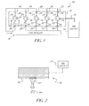
- FIG. 1 An exemplary printing system 10 is illustrated in Figure 1, wherein the printing system 10 can be implemented in a printer along with systems and methods described further herein.
- the printing system 10 comprises a print head 12, at least one ink supply 14, and a controller 16.
- the print head 12 can be formed from a semiconductor material, such as silicon, using fabrication techniques well known in the field.
- a plurality of nozzles 18 can be formed on the print head 12, wherein the nozzles 18 are in fluid communication with the ink supply 14 through an ink passage 20, also formed in the print head 12.
- a heater 22 is positioned or formed on the print head 12 at each nozzle 18 so as to facilitate the ejection of ink filaments from the nozzle 18 and break-up of the filaments into droplets.
- the heater 22 is implemented with a resistive heat element 24 coupled to electrical contact pads 26 via conductors 28.
- the contact pads 26 can be coupled to the controller 16 such that the controller 16 controls activation of the resistive heat element 24, thus controlling the production of the stream of ink droplets produced by the nozzles 18.
- Figure 2 is a cross-section of the print head 12 shown in Figure 1, illustrating the expulsion of ink from the nozzle 18.
- the print head 12 comprises a nozzle plate 40 having a plurality of nozzles, through which ink leaves the print head 12.
- ink from the ink supply 14 is ejected through the nozzle in the nozzle plate 40 of the print head 12 to create a filament 42 of ink.
- the resistive element 24 can be activated to break up the filament 42 into a stream of individual ink droplets 44 for deposition on a print medium.
- the area around the nozzles in the nozzle plate 40 are the primary areas where excess ink and debris form, which adversely affect the performance of the printer.
- the printing system 10 can be implemented, for example, in the printer 50 illustrated in FIGURE 3.
- Various exemplary embodiments of printer systems suitable for use with the present invention are described in more detail in U.S. Patent Application No. 09/751,232, filed December 28, 2000, and entitled "CONTINUOUS INK-JET PRINTING METHOD AND APPARATUS," hereby incorporated by reference in its entirety.
- the printer 50 employs a droplet deflection region 51 comprising a gas flow chamber 52 positioned near the nozzle plate 40 such that ink ejected from the nozzle 18 travels through the gas flow chamber 52 and out an opening 54 substantially aligned with the nozzle 18.
- Gas flow is provided by a gas source 56 and regulated by a gas flow regulator 58 prior to entry into the gas flow chamber 52.
- the gas flow source 56 can be, for example, an air supply or a nitrogen supply.
- a stream of large volume ink droplets and small volume ink droplets, formed from the ink filament 42, can be ejected from the nozzle 18 substantially along a path X.
- gas flow can be provided to the gas flow chamber 52 to apply a force to the stream of ink droplets ejected from the nozzle 18.
- the large volume ink droplets may continue along path X and into a catcher 74.
- the catcher 74 can be a porous element, a mesh screen, or a gutter type device.
- the catcher 74 catches ink ejected from the print head during start-up, shut down, or a cleaning procedure such that the ink is not allowed to reach the print medium 70.
- the catcher 74 routes the ink from the large volume ink droplets to, for example, an ink recovery system 66.
- a negative pressure source 68 can apply a negative pressure to the gutter the catcher 74.
- the negative pressure source 68 assists in the separation of the small ink droplets from the large ink droplets and the recovery of the ink droplets traveling substantially along path X.
- the printing path Y leads the small ink droplets to a print medium 70 supported on a print drum 72.
- the catcher 74 positioned at or near the opening 54, prevent ink droplets that stray from the printing path Y from contacting the print medium 70.
- small ink droplets are selectively generated that will follow path Y to the print medium at the desired locations.
- large droplets are generated which hit the catcher 74.
- An additional negative pressure source 76 can be provided at an outlet 78 of the gas flow chamber 52 so as to apply a negative pressure at the other end of the gas flow chamber 52 and assist in the separation of the small ink droplets and the large ink droplets. Also, the negative pressure source 76 can be coupled to the catcher 74 so as to assist in the removal of ink collected by the catcher 74 during operation.
- the outlet 78 of the gas flow chamber 52 may also have fluid communication with the ink recovery system 66.
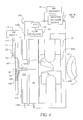
- FIGURE 4 illustrates a cross-sectional view of one embodiment of a start-up and shut down system 100, which can be implemented in the printer 50 in combination with the droplet deflector system 51.
- This embodiment comprises at least one porous element 102 and a negative pressure source 104.
- the porous element 102 comprises two porous elements having a separation therebetween.
- the porous element 102 has a surface 106 which may be approximately parallel and in close proximity to the nozzle plate 40 of the print head 12.
- the planar surface 106 may be in abutting contact with the nozzle plate 40.
- the porous element 102 comprises 85% Al 2 O 3 with a 40% average porosity and an average pore diameter of 20 ⁇ m.
- the nominal filtration level of the porous element 102 in water can be 5 ⁇ m.
- the described embodiment of the porous element 102 functions as a filter. Over time, the porous element 102 may be cleaned or replaced to maintain peak ink absorption.
- Capture of misdirected ink droplets and their removal from the porous element 102 can reduce the formation of a fluid film or fluid beads immediately adjacent to the nozzle plate 40. In this way, ink droplets which do not pass completely through the slit 108, do not adhere to the nozzle plate 40.
- a slit 108 formed in or by the porous element(s) 102 defines a passageway for the ink droplets 44 to pass when they are ejected from the print head 12.
- Different embodiments of the slit 108 can have different widths.
- the width of the slit 108 is 125 ⁇ m.
- the width of the slit 108 is 250 ⁇ m.
- the width of the slit 108 can vary with distance from the nozzles along the thickness of the porous element 102.
- a negative pressure source 104 may be coupled with the porous element 102.
- the negative pressure source 104 is analogous to the negative pressure sources 68, 76 previously described with reference to FIGURE 3.
- the ink supply 14 provides ink to an ink supply chamber 110.
- the ink supply chamber 110 can have an outlet 112 with a valve 114 so as to control the fluid pressure in the ink supply chamber 110.
- the nozzle plate 40 In communication with the ink supply chamber 110 is the nozzle plate 40 with a plurality of openings forming a respective plurality of ink ejection nozzles 18.
- the nozzle plate 40 is preferably formed from a material which exhibits a hydrophobic response to the selected ink. For example, a silicon plate could be used.
- a cleaning chamber 116 is located parallel to the ink supply chamber 110 and is in flow contact with the porous element 102 and the negative pressure source 104.
- the cleaning chamber 116 functions as a manifold for collecting the ink absorbed by the porous element 102.
- Ink droplets ejected from the nozzles 18 travel through the slit 108 in a perpendicular direction to the cleaning chamber 116.
- the slit 108 is substantially aligned with the nozzles 18.
- the ink droplets 44, which contact the porous element 102 as they pass through the slit 108 are absorbed by the porous element 102 and collect in the cleaning chamber 102.
- the ink droplets 44 that are absorbed by the porous element 102 are drawn into the cleaning chamber 116 in a flow direction substantially perpendicular to a direction in which ink is ejected from the nozzles 18.
- the negative pressure source 104 debris and excessive ink are cleared from the opening and surrounding area of the nozzles 18.
- the debris and excessive ink cleared by the cleaning chamber 116 flows out of the cleaning chamber and through outlets 118(a), 118(b) located at the ends of the cleaning chamber.
- the ink recovery system 66 is in flow communication with the outlets 118(a), 118(b) and is configured to recover the ink drawn from the porous element 102.
- an additional ink recovery system is used.
- the system is configured to perform a jet integrity sensing function.
- This function can be performed during steady state operation of the printer 50. For example, assuming that the nozzles 18 are operating properly, the closely spaced upper and lower surfaces of the porous element 102 are normally dry while printing when not starting or stopping the printer 50. However, the fluid from a partially occluded nozzle 18 that drips will be captured by the porous element 102. Once captured, a fluid presence sensor (not shown) may be provided to detect the fluid. Corrective action can then to taken to perform a cleaning procedure or maintenance operation to the printer 50. Thus, the presence of ink droplets 44 in the start-up and shut down system 100 during normal operation can indicate that one or more of the nozzles is leaking fluid.
- the gas flow chamber 52 of the drop deflector system 51 is positioned adjacent to the cleaning chamber 116, however the invention is not limited to such a structure.
- the gas flow chamber 52 is more particularly a substantially contained gas flow path positioned approximately parallel to the cleaning chamber 116, such that a stream of ink leaving the cleaning chamber 116 passes through a gas flow path of the drop deflector system 51.
- the droplet deflector system 51 can be implemented in a number of configurations in combination with the cleaning chamber 116 so as to effectively direct the appropriate ink droplets to the print media 70 in a desirable manner.
- FIGURE 5 is a side elevation view of the print head 12 spaced away a distance B from the porous element 102.
- the distance B is 250 ⁇ m.
- the slit 108 in the porous element 102 is illustrated as having a width A. In different advantageous embodiments, the width A may be anywhere from 125 to 250 ⁇ m.
- FIGURE 6 is a front elevation view of the nozzle plate 40 with the porous element 102 comprising two adjacent porous elements 102(a) and 102(b).
- the two porous elements 102(a), 102(b) are separated by the width A.
- the nozzles 18 are substantially aligned with the separation defined by width A.
- the porous element comprises an array of orifices substantially aligned with the nozzles 18. In this embodiment, ink droplets 44 which are misdirected in any plane will be captured by the porous element 102.
- FIGURE 7 is an illustration of a cross-sectional isometric view of another embodiment of the start-up and shut down system 100.
- the porous element 102 shown in FIGURE 7 includes faces 120 and 122.
- the faces 120, 122 are inclined at an angle relative to the direction of ink droplet ejection from the print head 12. By inclining the faces 120, 122 errant ink droplets 44 are drawn along the faces 120, 122 and away from the print head 12. It has been found that the inclination of the faces may enhance the absorption of the errant ink droplets 44.
- FIGURE 8 is an illustration of an alternate embodiment of the porous element 102 with the inner surface being non-planar.
- the surface may comprise concave surface features 124 and convex surface features 126.
- a combination of the convex and concave surface features can be used.
- the planar surface 106 can comprise an asymmetrical distribution of concave and/or convex surface features.
- the concave and convex surface features 124, 126 tend to act as collection sites for small fluid volumes. At least some of these sites are preferably located adjacent to the nozzles 18 so as to enhance the removal of errant ink droplets 44 from the region adjacent to the nozzles 18. As shown in FIGURE 8, the concave and convex surface features are located a distance B from the print head 12. As with the planar embodiments described above, the porous element 102 may alternatively be located adjacent to the print head 12 such that the distance B is substantially zero.
- FIGURE 9 is a cross-sectional view of an alternate embodiment of the printing system 50 from FIGURE 4 which includes the start-up and shut down system 100 and a fluid valve system 127.
- the fluid valve system 127 can be used alone or in conjunction with the start-up and shut down system 100.
- the start-up and shut down system 100 is as described with reference to FIGURE 4.
- the fluid valve system is configured to form a temporary barrier, or fluid bridge 132, between the ejected ink droplets 44 and the print medium 70. As will be explained, formation of the fluid bridge 132 is advantageous during start-up and/or shutdown phases of the printer 50.
- the embodiment of the fluid valve system 127 shown in FIGURE 9 comprises fluid valve porous elements 128, 130, a cleaning chamber 134, a valve 136, and a negative pressure source 104.
- the closely spaced surfaces of the fluid valve porous elements 128, 130 form a passageway for the ink droplets 44 to reach the print medium 70.
- the passageway can be, for example, 125 ⁇ m.
- the fluid valve porous elements 128, 130 are ported to the negative pressure source 104 via the cleaning chamber 134.
- the passageway or the fluid bridge 132 is formed between the fluid valve porous elements 128, 130.
- the fluid bridge 132 does not form and the ink droplets 44 pass through the fluid valve porous elements 128, 130.
- the fluid bridge 132 is established between the fluid valve porous elements 128, 130 when the valve 136 restricts the negative pressure source 104. When this occurs, the ink droplets 44 ejected from the nozzle plate 40 that pass through the porous element 102 and the gutter 60(a), 60(b) will not pass through the fluid bridge 132.
- the fluid bridge 132 can limit the errant ink fluid from leaving the print head 12 and striking the print medium 70. Moreover, the fluid bridge 132 further suppresses the momentary spray and nozzle deflection that occur when the fluid nozzles 18 first impinge the catcher 74 and /or gutter 60(a), 60(b) when the catcher and/or gutter are in a dry configuration.
- the volume of fluid in the fluid bridge 132 is correspondingly small and may be established and removed relatively quickly.
- the rapid creation and removal of the fluid bridge 132 act as a fast valve for the fluid nozzles 18.
- the fluid flow exiting the fluid valve porous elements 128, 130 to the cleaning chamber 134 would just equal the nozzle 18 flow rate in order to maintain the fluid bridge 132.
- Embodiments of the fluid valve system 127 comprise a perforated porous fluid valve element.
- the perforated fluid valve element comprises an array of passageways that are aligned with the nozzles 18 to form a plurality of fluid bridges.
- a diameter of the passageways is less than a pitch spacing of the nozzles.
- the diameter of the array of passageways can be 50 um with a nozzle 18 pitch spacing of 80 um.
- the nozzles 18 can have a 10 um diameter.
- the fluid bridge 132 can be incorporated into a printing system 10 that utilizes water and/or various inks ranging in viscosity from 1.0 to 4.5 cP and with drop velocities below 10 meters per second. At higher drop velocities, the fluid bridge 132 is less effective with the lower viscosity inks.
- a start-up and shut down system 100 and method is shown and described as implemented in a printer using air flow to direct a continuous stream of ink droplets, the systems and method described herein are not limited to such a printing system.
- the systems and methods described herein may be implemented in printing systems wherein, for example, electrostatic charge is used to direct ink droplets, or alternate configurations of air flow deflection of ink droplets are used. In such environments, the systems and methods of the described invention may be modified so as to effectively perform their intended functions.
Landscapes
- Ink Jet (AREA)
- Particle Formation And Scattering Control In Inkjet Printers (AREA)
Abstract
Description
- The present invention relates to inkjet printers, and more particularly to inkjet printers using a continuous ink stream type print head.
- Digitally controlled printing is typically accomplished using one of two technologies referred to as "drop-on-demand" and "continuous" inkjet printing. Both printing techniques utilize ink supplies for each color of ink, with the ink being ejected through nozzles formed in a print head.
- Drop-on-demand inkjet printing typically uses a thermal or mechanical actuator to provide ink droplets for deposition on a print medium. In continuous ink jet printing technology, ink is typically supplied to an ink reservoir in a print head under pressure so as to produce a jet, or continuous stream of ink from a nozzle in liquid communication with the reservoir. Periodic excitations are imposed on the ink stream to cause the stream to break up into ink droplets.
- Some continuous inkjet printers utilize air flow to control the trajectory of ink droplets ejected from a print head, wherein ink droplets can be deflected from their ejection path as they leave the print head to either a print medium or an ink capturing mechanism such as a catcher or gutter. The ink captured by the capturing mechanism can either be recycled back to the ink reservoir for reuse, or disposed of.
- Difficulties are often experienced during start-up of continuous stream ink jet printers, when the print head is in an initial dry nozzle plate condition. The ink driving pressure increases from zero but is initially too low to overcome surface tension and drive the ink out of the tiny nozzles in the nozzle plate. A transition period is then reached in which the ink driving pressure overcomes the surface tension effects to force some ink through the nozzles, but the pressure is still insufficient to produce well formed fluid jets of ink. During this transition period from the initial dry nozzle plate condition to fluid jets of ink, ink typically leaks from the print head nozzle and creates a fluid film or beads on the nozzle plate. A similar phenomenon occurs when the printer or print heads are shut down, after which the fluid film or beads can dry on the nozzle plate prior to the next start-up or printing operation of the print head.
- A fluid film formed at the nozzle plate increases the probability that fluid leaving the nozzle plate will never overcome the surface tension of the film formed at the nozzles. Fluid beads on the nozzle plate can cause nozzles under the beads to produce a continuous flow of ink that adheres to the nozzle plate. In addition, beads formed adjacent to nozzles can cause misdirection in ink ejected from such nozzles, and inconsistencies in droplet size and shape. The most common solution to clogged jets is to flush the nozzle, or plurality of nozzles with a large amount of ink, however such a method wastes the ink and is not always effective. In addition, this method may not remove the fluid beads from locations adjacent the nozzles, thus misdirected and misshapen drops continue to be ejected from the print head and produce poor quality print images.
- The systems and methods of the present invention have several features, no single one of which is solely responsible for its desirable attributes. Without limiting the scope of this invention as expressed by the claims which follow, its more prominent features will now be discussed briefly. After considering this discussion, and particularly after reading the section entitled "Detailed Description of the Invention" one will understand how the features of this invention provide several advantages over traditional ink jet printers.
- One aspect is a method of reducing accumulation of unwanted matter on a surface of a print head of an ink jet printer system during start-up and shutdown which comprises ejecting a stream of ink from the surface of the print head nozzles and into a slit in one or more porous elements, the stream of ink comprising, an aligned portion which follows a first path from the surface of the print head nozzles and through the slit in the porous element to a print medium, and a misdirected portion which follows a second path different than the first path, wherein the second path contacts a porous element, and absorbing the misdirected portion through a surface of the porous element.
- Another aspect is a system for removing unwanted particles from one or more print head nozzles, comprising means for absorbing the unwanted particles at the print head nozzle and a surrounding area.
- Still another aspect is a printing system that comprises a print head configured to eject a stream of ink from a plurality of nozzles and towards a print medium and a porous element positioned proximate to an ink ejection area of the plurality of nozzles, wherein an errant portion of the stream of ink is absorbed by the porous element during start up and shut down phases of printer operation.
- A further aspect is a method of making an ink jet printer comprising mounting a porous member within 250 um of a print head surface such that at least some misdirected ink is captured by said porous member during a start up phase of printer operation.
- Yet another aspect is an ink jet printing system that comprises a print head configured to output a stream of ink from a plurality of nozzles, and at least one porous member configured to form an absorption region in proximity to an ink ejection area of the plurality of nozzles, wherein the porous member absorbs a misdirected portion of the stream of ink.
- FIGURE 1 is an illustration of one embodiment of a printing system.
- FIGURE 2 is a cross-sectional view of the printing system of FIGURE 1.
- FIGURE 3 is a cross-sectional side view of one embodiment of a printer implementing the printing system of FIGURES 1-2.
- FIGURE 4 is a cross-sectional side view of one embodiment of a printing system incorporating a porous element.
- FIGURE 5 is a side elevation view of the print head spaced away a distance B from the porous element.
- FIGURE 6 is a front elevation view of the nozzle plate with the porous element comprising two adjacent porous elements.
- FIGURE 7 is an illustration of a cross-sectional isometric view of another embodiment of a printer that incorporates a porous element with inclined surfaces.
- FIGURE 8 is an illustration of an embodiment of a porous element that comprises concave surface features and convex surface features.
- FIGURE 9 is a cross-sectional view of an embodiment of the printer system from FIGURE 4 further comprising a fluid valve system.
-
- Embodiments of the invention will now be described with reference to the accompanying Figures, wherein like numerals refer to like elements throughout. The terminology used in the description presented herein is not intended to be interpreted in any limited or restrictive manner, simply because it is being utilized in conjunction with a detailed description of certain specific embodiments of the invention. Furthermore, embodiments of the invention may include several novel features, no single one of which is solely responsible for its desirable attributes or which is essential to practicing the inventions herein described.
- An
exemplary printing system 10 is illustrated in Figure 1, wherein theprinting system 10 can be implemented in a printer along with systems and methods described further herein. - The
printing system 10 comprises aprint head 12, at least oneink supply 14, and acontroller 16. Theprint head 12 can be formed from a semiconductor material, such as silicon, using fabrication techniques well known in the field. A plurality ofnozzles 18 can be formed on theprint head 12, wherein thenozzles 18 are in fluid communication with theink supply 14 through anink passage 20, also formed in theprint head 12. - In the embodiment of Figure 1, a
heater 22 is positioned or formed on theprint head 12 at eachnozzle 18 so as to facilitate the ejection of ink filaments from thenozzle 18 and break-up of the filaments into droplets. In the present embodiment, theheater 22 is implemented with aresistive heat element 24 coupled toelectrical contact pads 26 viaconductors 28. Thecontact pads 26 can be coupled to thecontroller 16 such that thecontroller 16 controls activation of theresistive heat element 24, thus controlling the production of the stream of ink droplets produced by thenozzles 18. - Figure 2 is a cross-section of the
print head 12 shown in Figure 1, illustrating the expulsion of ink from thenozzle 18. As can be seen in Figure 2, theprint head 12 comprises anozzle plate 40 having a plurality of nozzles, through which ink leaves theprint head 12. During operation, ink from theink supply 14 is ejected through the nozzle in thenozzle plate 40 of theprint head 12 to create afilament 42 of ink. Theresistive element 24 can be activated to break up thefilament 42 into a stream ofindividual ink droplets 44 for deposition on a print medium. The area around the nozzles in thenozzle plate 40 are the primary areas where excess ink and debris form, which adversely affect the performance of the printer. - It will be appreciated that the
printing system 10 as shown and described in reference to Figures 1 and 2 is exemplary in nature, and the invention is not limited to such a print system. - The
printing system 10 can be implemented, for example, in theprinter 50 illustrated in FIGURE 3. Various exemplary embodiments of printer systems suitable for use with the present invention are described in more detail in U.S. Patent Application No. 09/751,232, filed December 28, 2000, and entitled "CONTINUOUS INK-JET PRINTING METHOD AND APPARATUS," hereby incorporated by reference in its entirety. Theprinter 50 employs adroplet deflection region 51 comprising agas flow chamber 52 positioned near thenozzle plate 40 such that ink ejected from thenozzle 18 travels through thegas flow chamber 52 and out anopening 54 substantially aligned with thenozzle 18. Gas flow is provided by agas source 56 and regulated by agas flow regulator 58 prior to entry into thegas flow chamber 52. Thegas flow source 56 can be, for example, an air supply or a nitrogen supply. - A stream of large volume ink droplets and small volume ink droplets, formed from the
ink filament 42, can be ejected from thenozzle 18 substantially along a path X. In thedroplet deflector system 51, gas flow can be provided to thegas flow chamber 52 to apply a force to the stream of ink droplets ejected from thenozzle 18. In this way, the small volume ink droplets diverge from path X along a printing path Y. The large volume ink droplets may continue along path X and into acatcher 74. Thecatcher 74 can be a porous element, a mesh screen, or a gutter type device. In this way, thecatcher 74 catches ink ejected from the print head during start-up, shut down, or a cleaning procedure such that the ink is not allowed to reach theprint medium 70. Thecatcher 74 routes the ink from the large volume ink droplets to, for example, anink recovery system 66. - A negative pressure source 68 can apply a negative pressure to the gutter the
catcher 74. The negative pressure source 68 assists in the separation of the small ink droplets from the large ink droplets and the recovery of the ink droplets traveling substantially along path X. - The printing path Y leads the small ink droplets to a
print medium 70 supported on aprint drum 72. Thecatcher 74 positioned at or near theopening 54, prevent ink droplets that stray from the printing path Y from contacting theprint medium 70. During printing, small ink droplets are selectively generated that will follow path Y to the print medium at the desired locations. When no droplets are to be applied to the media, large droplets are generated which hit thecatcher 74. - An additional negative pressure source 76 can be provided at an
outlet 78 of thegas flow chamber 52 so as to apply a negative pressure at the other end of thegas flow chamber 52 and assist in the separation of the small ink droplets and the large ink droplets. Also, the negative pressure source 76 can be coupled to thecatcher 74 so as to assist in the removal of ink collected by thecatcher 74 during operation. Theoutlet 78 of thegas flow chamber 52 may also have fluid communication with theink recovery system 66. - One problem with the system shown in Figure 3 is that during start up and shut down of the printer system, ink from the print head may be ejected far off from path X, and collect near and on the print head itself. During this period, the catcher is generally ineffective as a means to keep ink which is not used for printing on the media from negatively affecting printer operation. A new method of dealing with this issue is presented below with reference to the following Figures.
- FIGURE 4 illustrates a cross-sectional view of one embodiment of a start-up and shut down
system 100, which can be implemented in theprinter 50 in combination with thedroplet deflector system 51. This embodiment comprises at least oneporous element 102 and a negative pressure source 104. Alternatively, theporous element 102 comprises two porous elements having a separation therebetween. - The
porous element 102 has asurface 106 which may be approximately parallel and in close proximity to thenozzle plate 40 of theprint head 12. Theplanar surface 106 may be in abutting contact with thenozzle plate 40. In one embodiment theporous element 102 comprises 85% Al2O3 with a 40% average porosity and an average pore diameter of 20 µm. The nominal filtration level of theporous element 102 in water can be 5 µm. The described embodiment of theporous element 102 functions as a filter. Over time, theporous element 102 may be cleaned or replaced to maintain peak ink absorption. - Capture of misdirected ink droplets and their removal from the
porous element 102 can reduce the formation of a fluid film or fluid beads immediately adjacent to thenozzle plate 40. In this way, ink droplets which do not pass completely through theslit 108, do not adhere to thenozzle plate 40. - A
slit 108 formed in or by the porous element(s) 102 defines a passageway for theink droplets 44 to pass when they are ejected from theprint head 12. Different embodiments of theslit 108 can have different widths. For example, in one embodiment the width of theslit 108 is 125 µm. In another embodiment, the width of theslit 108 is 250 µm. As will be described with reference to FIGURE 7, the width of theslit 108 can vary with distance from the nozzles along the thickness of theporous element 102. - In addition, a negative pressure source 104 may be coupled with the
porous element 102. In the embodiment shown in FIGURE 4, the negative pressure source 104 is analogous to the negative pressure sources 68, 76 previously described with reference to FIGURE 3. - Returning again to FIGURE 4, the
ink supply 14 provides ink to anink supply chamber 110. Theink supply chamber 110 can have anoutlet 112 with avalve 114 so as to control the fluid pressure in theink supply chamber 110. In communication with theink supply chamber 110 is thenozzle plate 40 with a plurality of openings forming a respective plurality of ink ejection nozzles 18. Thenozzle plate 40 is preferably formed from a material which exhibits a hydrophobic response to the selected ink. For example, a silicon plate could be used. - In one embodiment, a
cleaning chamber 116 is located parallel to theink supply chamber 110 and is in flow contact with theporous element 102 and the negative pressure source 104. Thecleaning chamber 116 functions as a manifold for collecting the ink absorbed by theporous element 102. Ink droplets ejected from thenozzles 18 travel through theslit 108 in a perpendicular direction to thecleaning chamber 116. Theslit 108 is substantially aligned with thenozzles 18. Theink droplets 44, which contact theporous element 102 as they pass through theslit 108 are absorbed by theporous element 102 and collect in thecleaning chamber 102. - As shown in FIGURE 4, the
ink droplets 44 that are absorbed by theporous element 102 are drawn into thecleaning chamber 116 in a flow direction substantially perpendicular to a direction in which ink is ejected from thenozzles 18. As the absorbedink droplets 44 are removed from thecleaning chamber 116 by the negative pressure source 104, debris and excessive ink are cleared from the opening and surrounding area of thenozzles 18. The debris and excessive ink cleared by thecleaning chamber 116 flows out of the cleaning chamber and through outlets 118(a), 118(b) located at the ends of the cleaning chamber. - In the embodiment illustrated in FIGURE 4, the
ink recovery system 66 is in flow communication with the outlets 118(a), 118(b) and is configured to recover the ink drawn from theporous element 102. Alternatively, an additional ink recovery system is used. - In another embodiment of the start-up and shut down
system 100, the system is configured to perform a jet integrity sensing function. This function can be performed during steady state operation of theprinter 50. For example, assuming that thenozzles 18 are operating properly, the closely spaced upper and lower surfaces of theporous element 102 are normally dry while printing when not starting or stopping theprinter 50. However, the fluid from a partially occludednozzle 18 that drips will be captured by theporous element 102. Once captured, a fluid presence sensor (not shown) may be provided to detect the fluid. Corrective action can then to taken to perform a cleaning procedure or maintenance operation to theprinter 50. Thus, the presence ofink droplets 44 in the start-up and shut downsystem 100 during normal operation can indicate that one or more of the nozzles is leaking fluid. - As described and shown herein, the
gas flow chamber 52 of thedrop deflector system 51 is positioned adjacent to thecleaning chamber 116, however the invention is not limited to such a structure. In one embodiment, thegas flow chamber 52 is more particularly a substantially contained gas flow path positioned approximately parallel to thecleaning chamber 116, such that a stream of ink leaving thecleaning chamber 116 passes through a gas flow path of thedrop deflector system 51. In addition, thedroplet deflector system 51 can be implemented in a number of configurations in combination with thecleaning chamber 116 so as to effectively direct the appropriate ink droplets to theprint media 70 in a desirable manner. - FIGURE 5 is a side elevation view of the
print head 12 spaced away a distance B from theporous element 102. In one embodiment, the distance B is 250 µm. Theslit 108 in theporous element 102 is illustrated as having a width A. In different advantageous embodiments, the width A may be anywhere from 125 to 250 µm. - FIGURE 6 is a front elevation view of the
nozzle plate 40 with theporous element 102 comprising two adjacent porous elements 102(a) and 102(b). The two porous elements 102(a), 102(b) are separated by the width A. As shown in FIGURE 6, thenozzles 18 are substantially aligned with the separation defined by width A. In another embodiment of theporous element 102, the porous element comprises an array of orifices substantially aligned with thenozzles 18. In this embodiment,ink droplets 44 which are misdirected in any plane will be captured by theporous element 102. - FIGURE 7 is an illustration of a cross-sectional isometric view of another embodiment of the start-up and shut down
system 100. Theporous element 102 shown in FIGURE 7 includesfaces print head 12. By inclining thefaces errant ink droplets 44 are drawn along thefaces print head 12. It has been found that the inclination of the faces may enhance the absorption of theerrant ink droplets 44. - FIGURE 8 is an illustration of an alternate embodiment of the
porous element 102 with the inner surface being non-planar. In these embodiments, the surface may comprise concave surface features 124 and convex surface features 126. As illustrated in FIGURE 8, a combination of the convex and concave surface features can be used. Theplanar surface 106 can comprise an asymmetrical distribution of concave and/or convex surface features. - The concave and convex surface features 124, 126 tend to act as collection sites for small fluid volumes. At least some of these sites are preferably located adjacent to the
nozzles 18 so as to enhance the removal oferrant ink droplets 44 from the region adjacent to thenozzles 18. As shown in FIGURE 8, the concave and convex surface features are located a distance B from theprint head 12. As with the planar embodiments described above, theporous element 102 may alternatively be located adjacent to theprint head 12 such that the distance B is substantially zero. - FIGURE 9 is a cross-sectional view of an alternate embodiment of the
printing system 50 from FIGURE 4 which includes the start-up and shut downsystem 100 and afluid valve system 127. Thefluid valve system 127 can be used alone or in conjunction with the start-up and shut downsystem 100. The start-up and shut downsystem 100 is as described with reference to FIGURE 4. The fluid valve system is configured to form a temporary barrier, orfluid bridge 132, between the ejectedink droplets 44 and theprint medium 70. As will be explained, formation of thefluid bridge 132 is advantageous during start-up and/or shutdown phases of theprinter 50. - The embodiment of the
fluid valve system 127 shown in FIGURE 9 comprises fluid valveporous elements cleaning chamber 134, avalve 136, and a negative pressure source 104. The closely spaced surfaces of the fluid valveporous elements ink droplets 44 to reach theprint medium 70. The passageway can be, for example, 125 µm. The fluid valveporous elements cleaning chamber 134. - Depending on the operational state of the negative pressure source 104, the passageway or the
fluid bridge 132 is formed between the fluid valveporous elements fluid bridge 132 does not form and theink droplets 44 pass through the fluid valveporous elements fluid bridge 132 is established between the fluid valveporous elements valve 136 restricts the negative pressure source 104. When this occurs, theink droplets 44 ejected from thenozzle plate 40 that pass through theporous element 102 and the gutter 60(a), 60(b) will not pass through thefluid bridge 132. This creates a robust fluid shutter capable of nullifying the undesirable effects oftransient nozzle 18 behavior such as misting and misdirection associated with start-up and shut-down. Thefluid bridge 132 can limit the errant ink fluid from leaving theprint head 12 and striking theprint medium 70. Moreover, thefluid bridge 132 further suppresses the momentary spray and nozzle deflection that occur when thefluid nozzles 18 first impinge thecatcher 74 and /or gutter 60(a), 60(b) when the catcher and/or gutter are in a dry configuration. - Since the passageway between the fluid valve
porous elements fluid bridge 132 is correspondingly small and may be established and removed relatively quickly. The rapid creation and removal of thefluid bridge 132 act as a fast valve for thefluid nozzles 18. The fluid flow exiting the fluid valveporous elements cleaning chamber 134 would just equal thenozzle 18 flow rate in order to maintain thefluid bridge 132. - Embodiments of the
fluid valve system 127 comprise a perforated porous fluid valve element. The perforated fluid valve element comprises an array of passageways that are aligned with thenozzles 18 to form a plurality of fluid bridges. In some embodiments, a diameter of the passageways is less than a pitch spacing of the nozzles. For example, the diameter of the array of passageways can be 50 um with anozzle 18 pitch spacing of 80 um. Thenozzles 18 can have a 10 um diameter. - The
fluid bridge 132 can be incorporated into aprinting system 10 that utilizes water and/or various inks ranging in viscosity from 1.0 to 4.5 cP and with drop velocities below 10 meters per second. At higher drop velocities, thefluid bridge 132 is less effective with the lower viscosity inks. - Although a start-up and shut down
system 100 and method is shown and described as implemented in a printer using air flow to direct a continuous stream of ink droplets, the systems and method described herein are not limited to such a printing system. The systems and methods described herein may be implemented in printing systems wherein, for example, electrostatic charge is used to direct ink droplets, or alternate configurations of air flow deflection of ink droplets are used. In such environments, the systems and methods of the described invention may be modified so as to effectively perform their intended functions. - The foregoing description details certain embodiments of the invention. It will be appreciated, however, that no matter how detailed the foregoing appears in text, the invention can be practiced in many ways. As is also stated above, it should be noted that the use of particular terminology when describing certain features or aspects of the invention should not be taken to imply that the terminology is being re-defined herein to be restricted to including any specific characteristics of the features or aspects of the invention with which that terminology is associated. The scope of the invention should therefore be construed in accordance with the appended claims and any equivalents thereof.
- The invention has been described in detail with particular reference to certain preferred embodiments thereof, but it will be understood that variations and modifications can be effected within the scope of the invention.
Claims (10)
- An ink jet printing system, comprising:a print head (12) configured to output a stream of ink from a plurality of nozzles (18); andat least one porous member (102) configured to form an absorption region in proximity to an ink ejection area of the plurality of nozzles, wherein the porous member absorbs a misdirected portion of the stream of ink.
- The ink jet print system of Claim 1, further comprising a negative gas pressure source (68) in flow communication with the porous member and configured to draw the misdirected portion of the stream of ink from the porous member.
- The ink jet print system of Claim 2, wherein the misdirected portion of the stream of ink is drawn at a flow rate sufficient to remove debris and excess ink from the ink ejection area.
- The ink jet print system of Claim 2, further comprising a cleaning chamber located between the porous member and the negative pressure source to form a collection manifold for the misdirected portion of the stream of ink.
- The ink jet print system of Claim 2, wherein the at least one porous member forms a slit (108) substantially aligned with the plurality of nozzles.
- The ink jet print system of Claim 1, wherein the at least one porous member comprises an array of passageways therethrough which are substantially aligned with the plurality of nozzles and configured to allow an aligned portion of the stream of ink to pass through the at least one porous member.
- The ink jet print system of Claim 1, wherein the at least one porous member comprises a first porous member (102a) and a second porous (102b) member, the first and second porous members being separated by a space to form a slit substantially aligned with the plurality of nozzles.
- The ink jet print system of Claim 2 further comprising:at least one fluid valve porous element (128) in flow communication with the negative pressure source (104) and comprising an array of passageways therethrough which are substantially aligned with the plurality of nozzles to form transient fluid bridges in a flow path of an aligned portion of the stream of ink; anda valve (136) coupled to the negative pressure source and configured to vary a pressure in the at least one fluid valve porous element to control formation of the transient fluid bridges.
- A method of reducing accumulation of unwanted matter on a surface of a print head of an ink jet printer system during start-up and shutdown, the method comprising:ejecting a stream of ink from the surface of the print head nozzles and into a slit in one or more porous elements, the stream of ink comprising,an aligned portion which follows a first path from the surface of the print head nozzles and through the slit in the porous element to a print medium, anda misdirected portion which follows a second path different than the first path, wherein the second path contacts a porous element; andabsorbing the misdirected portion through a surface of the porous element.
- The method of Claim 9, further comprising:blocking the first path at a location downstream of the porous element with a fluid bridge, wherein the fluid bridge is formed through a fluid valve porous element, the fluid valve porous element being ported to a negative pressure source;decreasing a pressure in the fluid valve porous element; andabsorbing the fluid bridge into the fluid valve porous element in response to the decreasing pressure.
Applications Claiming Priority (2)
| Application Number | Priority Date | Filing Date | Title |
|---|---|---|---|
| US320884 | 1981-11-13 | ||
| US10/320,884 US6808246B2 (en) | 2002-12-17 | 2002-12-17 | Start-up and shut down of continuous inkjet print head |
Publications (2)
| Publication Number | Publication Date |
|---|---|
| EP1431039A1 true EP1431039A1 (en) | 2004-06-23 |
| EP1431039B1 EP1431039B1 (en) | 2009-04-01 |
Family
ID=32392989
Family Applications (1)
| Application Number | Title | Priority Date | Filing Date |
|---|---|---|---|
| EP03078837A Expired - Lifetime EP1431039B1 (en) | 2002-12-17 | 2003-12-05 | Start-up and shut down of continuous inkjet print head |
Country Status (4)
| Country | Link |
|---|---|
| US (1) | US6808246B2 (en) |
| EP (1) | EP1431039B1 (en) |
| JP (1) | JP4414213B2 (en) |
| DE (1) | DE60326919D1 (en) |
Cited By (2)
| Publication number | Priority date | Publication date | Assignee | Title |
|---|---|---|---|---|
| WO2009120278A1 (en) * | 2008-03-28 | 2009-10-01 | Eastman Kodak Company | Improved fluid flow in microfluidic devices |
| WO2012014379A1 (en) * | 2010-07-28 | 2012-02-02 | Canon Kabushiki Kaisha | Liquid ejection head and liquid ejection apparatus |
Families Citing this family (15)
| Publication number | Priority date | Publication date | Assignee | Title |
|---|---|---|---|---|
| CA2380671A1 (en) * | 2002-04-05 | 2003-10-05 | Stephane Dufresne | Needleless syringe for the subcutaneous injection of medicated droplets |
| US7918530B2 (en) | 2006-02-03 | 2011-04-05 | Rr Donnelley | Apparatus and method for cleaning an inkjet printhead |
| US7303265B1 (en) * | 2006-10-06 | 2007-12-04 | Eastman Kodak Company | Air deflected drop liquid pattern deposition apparatus and methods |
| US8172348B2 (en) | 2008-03-24 | 2012-05-08 | Hewlett-Packard Development Company, L.P. | Print head cap vent |
| JP5541724B2 (en) * | 2010-11-01 | 2014-07-09 | キヤノン株式会社 | Liquid discharge head and liquid discharge apparatus |
| US8403457B2 (en) | 2011-02-04 | 2013-03-26 | Xerox Corporation | Waste ink reclamation apparatus for liquid ink recirculation system |
| WO2013134737A1 (en) | 2012-03-09 | 2013-09-12 | R. R. Donnelley & Sons Company | System and method for cleaning inkjet cartridges |
| US8888208B2 (en) | 2012-04-27 | 2014-11-18 | R.R. Donnelley & Sons Company | System and method for removing air from an inkjet cartridge and an ink supply line |
| US9216581B2 (en) | 2013-02-08 | 2015-12-22 | R.R. Donnelley & Sons Company | Apparatus and method for wiping an inkjet cartridge nozzle plate |
| US8870340B2 (en) | 2013-02-28 | 2014-10-28 | Ricoh Company, Ltd | Dynamic drop redirection for drop on demand printing |
| CN108778753B (en) | 2016-03-04 | 2020-04-21 | R.R.当纳利父子公司 | Print head maintenance station and its operation method |
| CN207291314U (en) | 2016-05-09 | 2018-05-01 | R.R.当纳利父子公司 | Ink feeding unit |
| WO2018027678A1 (en) * | 2016-08-10 | 2018-02-15 | The University Of Hong Kong | Accelerating the breakup of fluid bridges for micro-dispensing applications |
| WO2023126105A1 (en) * | 2021-12-29 | 2023-07-06 | Asml Netherlands B.V. | Debris mitigation in an extreme ultraviolet light source |
| CN117719254B (en) * | 2024-01-09 | 2026-03-17 | 广东希望高科数字技术有限公司 | An ink supply system, a digital printing device, and an ink supply control method. |
Citations (3)
| Publication number | Priority date | Publication date | Assignee | Title |
|---|---|---|---|---|
| US4240082A (en) * | 1979-02-28 | 1980-12-16 | The Mead Corporation | Momentumless shutdown of a jet drop recorder |
| US4514735A (en) * | 1983-08-12 | 1985-04-30 | The Mead Corporation | Ink jet printer start-up and shutdown |
| US4628331A (en) * | 1980-11-18 | 1986-12-09 | Ricoh Company, Ltd. | Ink mist collection apparatus for ink jet printer |
Family Cites Families (3)
| Publication number | Priority date | Publication date | Assignee | Title |
|---|---|---|---|---|
| US4024548A (en) * | 1976-06-07 | 1977-05-17 | International Business Machines Corporation | Liquid absorbing assembly with two porosities |
| US6079821A (en) * | 1997-10-17 | 2000-06-27 | Eastman Kodak Company | Continuous ink jet printer with asymmetric heating drop deflection |
| US6588888B2 (en) | 2000-12-28 | 2003-07-08 | Eastman Kodak Company | Continuous ink-jet printing method and apparatus |
-
2002
- 2002-12-17 US US10/320,884 patent/US6808246B2/en not_active Expired - Fee Related
-
2003
- 2003-12-05 DE DE60326919T patent/DE60326919D1/en not_active Expired - Lifetime
- 2003-12-05 EP EP03078837A patent/EP1431039B1/en not_active Expired - Lifetime
- 2003-12-16 JP JP2003417711A patent/JP4414213B2/en not_active Expired - Fee Related
Patent Citations (3)
| Publication number | Priority date | Publication date | Assignee | Title |
|---|---|---|---|---|
| US4240082A (en) * | 1979-02-28 | 1980-12-16 | The Mead Corporation | Momentumless shutdown of a jet drop recorder |
| US4628331A (en) * | 1980-11-18 | 1986-12-09 | Ricoh Company, Ltd. | Ink mist collection apparatus for ink jet printer |
| US4514735A (en) * | 1983-08-12 | 1985-04-30 | The Mead Corporation | Ink jet printer start-up and shutdown |
Cited By (4)
| Publication number | Priority date | Publication date | Assignee | Title |
|---|---|---|---|---|
| WO2009120278A1 (en) * | 2008-03-28 | 2009-10-01 | Eastman Kodak Company | Improved fluid flow in microfluidic devices |
| US8585179B2 (en) | 2008-03-28 | 2013-11-19 | Eastman Kodak Company | Fluid flow in microfluidic devices |
| WO2012014379A1 (en) * | 2010-07-28 | 2012-02-02 | Canon Kabushiki Kaisha | Liquid ejection head and liquid ejection apparatus |
| US8636349B2 (en) | 2010-07-28 | 2014-01-28 | Canon Kabushiki Kaisha | Liquid ejection head and liquid ejection apparatus |
Also Published As
| Publication number | Publication date |
|---|---|
| JP4414213B2 (en) | 2010-02-10 |
| DE60326919D1 (en) | 2009-05-14 |
| JP2004195978A (en) | 2004-07-15 |
| US20040113970A1 (en) | 2004-06-17 |
| US6808246B2 (en) | 2004-10-26 |
| EP1431039B1 (en) | 2009-04-01 |
Similar Documents
| Publication | Publication Date | Title |
|---|---|---|
| EP1431039B1 (en) | Start-up and shut down of continuous inkjet print head | |
| US6899410B2 (en) | Continuous ink-jet printing apparatus with integral cleaning | |
| EP1277578B1 (en) | A continuous ink-jet printing apparatus with pre-conditioned air flow | |
| CN101678676B (en) | Printing device, printhead and printing method with improved airflow droplet deflection | |
| US8523327B2 (en) | Printhead including port after filter | |
| US20110205306A1 (en) | Reinforced membrane filter for printhead | |
| US7399068B2 (en) | Continuous ink jet printing apparatus with integral deflector and gutter structure | |
| EP1186424B1 (en) | Ink drop catcher assembly | |
| US7967423B2 (en) | Pressure modulation cleaning of jetting module nozzles | |
| JP4680499B2 (en) | Droplet deposition device | |
| US6848766B2 (en) | Start-up and shut down of continuous inkjet print head | |
| US8382258B2 (en) | Moving liquid curtain catcher | |
| US8398221B2 (en) | Printing using liquid film porous catcher surface | |
| US8337003B2 (en) | Catcher including drag reducing drop contact surface | |
| US20110204018A1 (en) | Method of manufacturing filter for printhead | |
| EP1403071B1 (en) | Wicking arrangement to eliminate catcher dripping | |
| US9174438B2 (en) | Liquid film moving over porous catcher surface | |
| US20120026252A1 (en) | Printing method using moving liquid curtain catcher | |
| US8091990B2 (en) | Continuous printhead contoured gas flow device | |
| WO2012018498A1 (en) | Printing using liquid film porous catcher surface | |
| WO2014164166A1 (en) | Printhead including coanda catcher with grooved radius |
Legal Events
| Date | Code | Title | Description |
|---|---|---|---|
| PUAI | Public reference made under article 153(3) epc to a published international application that has entered the european phase |
Free format text: ORIGINAL CODE: 0009012 |
|
| AK | Designated contracting states |
Kind code of ref document: A1 Designated state(s): AT BE BG CH CY CZ DE DK EE ES FI FR GB GR HU IE IT LI LU MC NL PT RO SE SI SK TR |
|
| AX | Request for extension of the european patent |
Extension state: AL LT LV MK |
|
| 17P | Request for examination filed |
Effective date: 20041109 |
|
| AKX | Designation fees paid |
Designated state(s): DE FR GB |
|
| 17Q | First examination report despatched |
Effective date: 20070508 |
|
| GRAP | Despatch of communication of intention to grant a patent |
Free format text: ORIGINAL CODE: EPIDOSNIGR1 |
|
| GRAS | Grant fee paid |
Free format text: ORIGINAL CODE: EPIDOSNIGR3 |
|
| GRAA | (expected) grant |
Free format text: ORIGINAL CODE: 0009210 |
|
| AK | Designated contracting states |
Kind code of ref document: B1 Designated state(s): DE FR GB |
|
| REG | Reference to a national code |
Ref country code: GB Ref legal event code: FG4D |
|
| REF | Corresponds to: |
Ref document number: 60326919 Country of ref document: DE Date of ref document: 20090514 Kind code of ref document: P |
|
| PLBE | No opposition filed within time limit |
Free format text: ORIGINAL CODE: 0009261 |
|
| STAA | Information on the status of an ep patent application or granted ep patent |
Free format text: STATUS: NO OPPOSITION FILED WITHIN TIME LIMIT |
|
| 26N | No opposition filed |
Effective date: 20100105 |
|
| PGFP | Annual fee paid to national office [announced via postgrant information from national office to epo] |
Ref country code: GB Payment date: 20131126 Year of fee payment: 11 |
|
| PGFP | Annual fee paid to national office [announced via postgrant information from national office to epo] |
Ref country code: FR Payment date: 20131126 Year of fee payment: 11 |
|
| PGFP | Annual fee paid to national office [announced via postgrant information from national office to epo] |
Ref country code: DE Payment date: 20141222 Year of fee payment: 12 |
|
| GBPC | Gb: european patent ceased through non-payment of renewal fee |
Effective date: 20141205 |
|
| REG | Reference to a national code |
Ref country code: FR Ref legal event code: ST Effective date: 20150831 |
|
| PG25 | Lapsed in a contracting state [announced via postgrant information from national office to epo] |
Ref country code: GB Free format text: LAPSE BECAUSE OF NON-PAYMENT OF DUE FEES Effective date: 20141205 |
|
| PG25 | Lapsed in a contracting state [announced via postgrant information from national office to epo] |
Ref country code: FR Free format text: LAPSE BECAUSE OF NON-PAYMENT OF DUE FEES Effective date: 20141231 |
|
| REG | Reference to a national code |
Ref country code: DE Ref legal event code: R119 Ref document number: 60326919 Country of ref document: DE |
|
| PG25 | Lapsed in a contracting state [announced via postgrant information from national office to epo] |
Ref country code: DE Free format text: LAPSE BECAUSE OF NON-PAYMENT OF DUE FEES Effective date: 20160701 |