EP1429498A2 - Network system and method with centralized flow behavioral mapping between layers - Google Patents
Network system and method with centralized flow behavioral mapping between layers Download PDFInfo
- Publication number
- EP1429498A2 EP1429498A2 EP03026349A EP03026349A EP1429498A2 EP 1429498 A2 EP1429498 A2 EP 1429498A2 EP 03026349 A EP03026349 A EP 03026349A EP 03026349 A EP03026349 A EP 03026349A EP 1429498 A2 EP1429498 A2 EP 1429498A2
- Authority
- EP
- European Patent Office
- Prior art keywords
- layers
- network
- behavior
- layer
- routers
- Prior art date
- Legal status (The legal status is an assumption and is not a legal conclusion. Google has not performed a legal analysis and makes no representation as to the accuracy of the status listed.)
- Withdrawn
Links
Images


Classifications
-
- H—ELECTRICITY
- H04—ELECTRIC COMMUNICATION TECHNIQUE
- H04L—TRANSMISSION OF DIGITAL INFORMATION, e.g. TELEGRAPHIC COMMUNICATION
- H04L45/00—Routing or path finding of packets in data switching networks
- H04L45/42—Centralised routing
-
- H—ELECTRICITY
- H04—ELECTRIC COMMUNICATION TECHNIQUE
- H04L—TRANSMISSION OF DIGITAL INFORMATION, e.g. TELEGRAPHIC COMMUNICATION
- H04L45/00—Routing or path finding of packets in data switching networks
-
- H—ELECTRICITY
- H04—ELECTRIC COMMUNICATION TECHNIQUE
- H04L—TRANSMISSION OF DIGITAL INFORMATION, e.g. TELEGRAPHIC COMMUNICATION
- H04L47/00—Traffic control in data switching networks
- H04L47/10—Flow control; Congestion control
- H04L47/24—Traffic characterised by specific attributes, e.g. priority or QoS
- H04L47/2491—Mapping quality of service [QoS] requirements between different networks
-
- H—ELECTRICITY
- H04—ELECTRIC COMMUNICATION TECHNIQUE
- H04L—TRANSMISSION OF DIGITAL INFORMATION, e.g. TELEGRAPHIC COMMUNICATION
- H04L69/00—Network arrangements, protocols or services independent of the application payload and not provided for in the other groups of this subclass
- H04L69/16—Implementation or adaptation of Internet protocol [IP], of transmission control protocol [TCP] or of user datagram protocol [UDP]
- H04L69/161—Implementation details of TCP/IP or UDP/IP stack architecture; Specification of modified or new header fields
-
- H—ELECTRICITY
- H04—ELECTRIC COMMUNICATION TECHNIQUE
- H04L—TRANSMISSION OF DIGITAL INFORMATION, e.g. TELEGRAPHIC COMMUNICATION
- H04L69/00—Network arrangements, protocols or services independent of the application payload and not provided for in the other groups of this subclass
- H04L69/30—Definitions, standards or architectural aspects of layered protocol stacks
- H04L69/32—Architecture of open systems interconnection [OSI] 7-layer type protocol stacks, e.g. the interfaces between the data link level and the physical level
-
- H—ELECTRICITY
- H04—ELECTRIC COMMUNICATION TECHNIQUE
- H04L—TRANSMISSION OF DIGITAL INFORMATION, e.g. TELEGRAPHIC COMMUNICATION
- H04L69/00—Network arrangements, protocols or services independent of the application payload and not provided for in the other groups of this subclass
- H04L69/16—Implementation or adaptation of Internet protocol [IP], of transmission control protocol [TCP] or of user datagram protocol [UDP]
Definitions
- the present embodiments relate to computer networks and are more particularly directed to a method and apparatus to map network packet behaviors from one architectural model layer to another architectural model layer.
- An architectural model provides a common frame of reference for discussing communications along a computer network, and it separates the functions performed along the network into different layers stacked on top of one another. Each layer provides a predefined interface to the layer above it.
- OSI Open Systems Interconnection
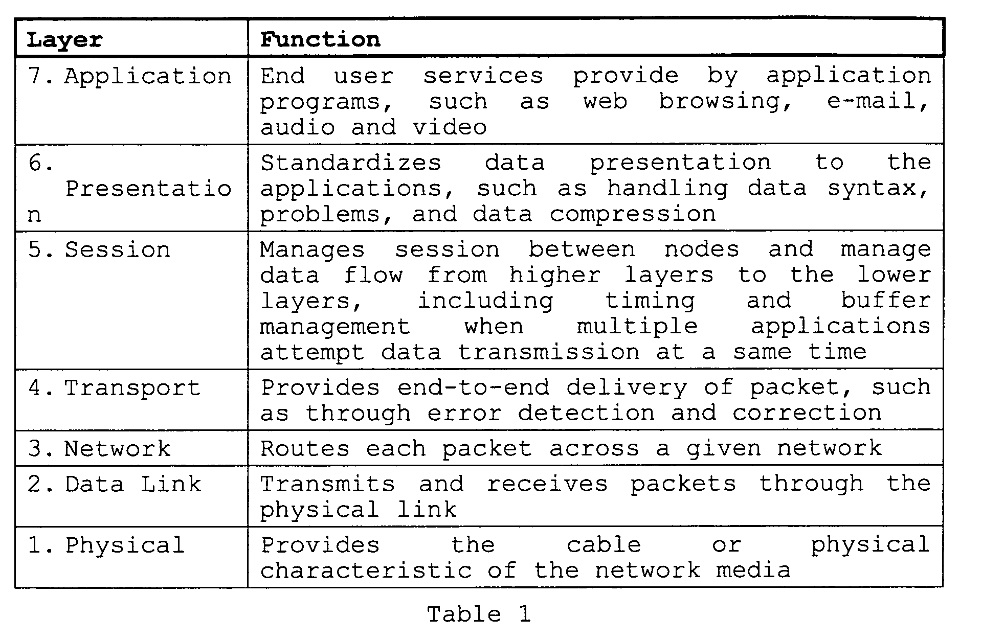
- the Open Systems Interconnection (“OSI") reference model has seven layers, typically defined as shown in the following Table 1:
- TCP transmission control protocol
- IP internet control protocol
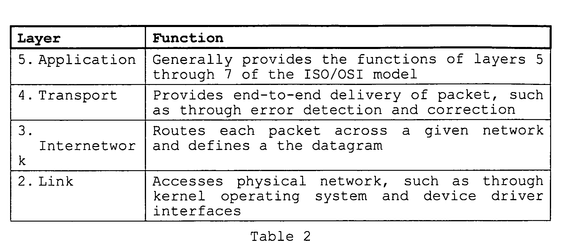
- reference model is sometimes described using three to five layers, and most commonly as having four layers.
- each layer at a given node can communicate with the same layer at another node and, more particularly, each layer protocol at one node can communicate with a peer protocol in the equivalent layer at another node.
- one layer does not care about the layer(s) above or below it, although there is a dependency in that every layer is involved in sending data from a local application to an equivalent remote application.
- the layers are required to have a manner of passing data between themselves on a single node and the upper layers rely on the lower layers to communicate data to the underlying network.
- QoS quality of service
- network communications were sometimes attempted or achieved using ordinary "best effort" protocols.
- QoS is therefore used with such applications so that transmission rates, error rates, and other characteristics can be measured, improved, and, to some extent, guaranteed in advance.
- RSVP Resource Reservation Protocol
- ATM asynchronous transfer mode
- QoS is currently implemented in layer 3 of TCP/IP networks in connection with two types of services, namely, integrated services and differentiated services.
- Integrated services relate to a single network flow, where a flow is commonly defined as a session of packets from a single source node to one destination node (and possibly others), where the flow is sometimes also recognized by having an actual flow identifier in the packet or it may be identified by various indicators such as when using ATM.
- QoS is presently achieved for integrated services using the RSVP to reserve resources in advance of transmitting the flow packets. Note, however, that QoS for integrated services is limited in that in a big network there may be millions of resources, so it is not feasible to scale the resource reservation across the entirety of the network.
- Differentiated services is a protocol that may apply to multiple flows, as opposed to the single flow nature of integrated services.
- Differentiated services presently are categorized by a six-bit control field known as a differentiated services control point ("DSCP"), where the DSCP is a field in each packet and can relate to multiple flows that each have an attribute that gives rise to a desire to treat each of the flows in a certain manner.
- DSCP differentiated services control point
- all flows corresponding to that DSCP are considered a type of network traffic by class and the traffic in that class gets a particular level of priority in its routing treatment.
- the current 6-bit DSCP is considered to be an implementation of a so-called per hop behavior ("PHB"), that is, in layer 3, it is desired for certain multiple flow packets to have a certain behavior, which typically is a quantifiable performance measure such as end-to-end delay.
- PHB per hop behavior
- DSCP is an implementation tool to achieve behavior at layer 3.
- differentiated services avoid simple priority tagging and depend on more complex policy or rule statements to determine how to forward a given network packet , and it is more flexible and more scaleable than the routing available to integrated services.
- QoS in the form of layer 3 DSCP has in some instances in the prior art been mapped to layer 2 by individual routers. Under such an approach, each such router is given autonomy to provide a relationship between the layer 3 DSCP and a layer 2 priority, thereby attempting to achieve a QoS in layer 2 based on the layer 3 DSCP.
- this prior art approach may provide inconsistent, or at least different, QoS treatments by individual routers based upon the manner in which they implement mapping. Further, such an approach generally provides only a relatively localized effect at each location of an individually-mapping router.
- the preferred embodiments are directed to providing consistent mapping between layers, such as between layer 3 DSPC and layer 2, across numerous routers distributed at multiple locations within a network. Further and as appreciated later, when a change in the mapping is desired, that change can be implemented at a single central location and then broadcast to multiple routers, thereby allowing a uniform change at comparable times and at the location of the multiple routers receiving the broadcast.
- the present state of the art typically implements the QoS of differentiated services in connection with the core routers of a network.
- the benefits of differentiated services are generally realized in a coarse manner at the more central core area of the network.
- improvements also may be made with respect to the so-called last mile problem, that is, in the prioritizing of packet communications both at and beyond the edge routers of a network, such as in the communication at a local area network connected to an edge router.
- the present inventors have recognized that as networks and network complexity increase, there is a need for greater consistency in QoS and behavior control across larger portions of the network. Indeed, as the number of different behaviors and/or DSCPs at each layer increases, the need for consistency in traffic treatment is even greater. Thus, there arises a need to expand certain benefits of the prior art while addressing the last-mile problem and the increasing demands on QoS, as is accomplished by the preferred embodiments described below.
- the system comprises a network having an architectural model comprising a plurality of layers.
- the system also comprises a centralized manager node, coupled to the network.
- the system also comprises a plurality of routers coupled to the network for communicating packets along the network and coupled to communicate with the centralized manager node.
- the centralized manager is programmed to perform the step of communicating mapping information to each of the plurality of routers, and the mapping information comprises a correspondence of a behavior on a first of the plurality of layers with a behavior on a second of the plurality of layers.
- Figure 1 illustrates a block diagram of a network system 10 into which the preferred embodiments are implemented.
- Figure 2 illustrates a flow chart of a method of operation with respect to any of the edge routers ER 1 through ER 4 and centralized manager CM 1 of Figure 1.
- FIG. 1 illustrates a diagram of a system 10 into which the preferred embodiments may be implemented by way of example.
- system 10 generally includes a wide area network WAN 1 coupled to two local area networks LAN 1 and LAN 2 . While the terms wide area network and local area network are sometimes used differently in various contexts, they are shown and used in this document by way of example insofar as network packets may be routed along various different nodes in such types of networks. Further, the term node is intended to suggest any device along system 10 that is operable to send or receive packets.
- system 10 is an internet protocol ("IP") system with IP networks WAN 1 and LAN 1 and LAN 2 , such as the global internet or other IP-using network.
- IP internet protocol
- IP protocol is by way of illustration, and many of the various inventive teachings herein may apply to numerous other protocols.
- IP packets flow along the various illustrated paths of system 10, and in groups or in their entirety such packets are often referred to as network traffic.
- the preferred embodiments operate to improve the handling of such network traffic at multiple network layers based on the desired behavior to be achieved for such traffic.
- Figure 1 may represent a simplified version of a network or the internet in that only a relatively small number of nodes are shown, while one skilled in the art will readily appreciate that the inventive concepts in this document may be applied to a larger number of nodes and the network interconnectivity between those devices.
- local area network LAN 1 includes four nodes N 1.1 through N 1.4 , where each node N 1. x may be constructed and function as one of various different types of computing devices, all capable of communicating according to the IP protocol.
- local area network LAN 2 includes four nodes N 2.1 through N 2.4 , also constructed and functioning as one of various different types of IP protocol communicating devices. While not expressly shown, it should be understood that with each local area network LAN x its nodes are coupled with some type of network medium to communicate with one another. Further, each local area network LAN x is also connected to communicate with wide area network WAN 1 .
- each local area network LAN x is also able to communicate, via wide area network WAN 1 , with the other local area network LAN x .
- WAN 1 wide area network
- each local area network LAN x may be proximate other nodes and networks (not shown) and at a geography located at a considerable distance from the other illustrated stations.
- local area network LAN 1 might be located in California while local area network LAN 2 might be located in New York.
- Wide area network WAN 1 is shown to include a number of edge routers ER 1 through ER 4 . Each edge router is connected to communicate with one or more additional edge routers as well as to at least one corresponding core router. For example, edge router ER 1 is connected to edge routers ER 2 and ER 4 as well as a core router CR 1 .
- edge router and core router are known in the art and generally relate to the function and relative network location of a router. Typically, edge routers connect to remotely located networks and handle considerably less traffic than core routers.
- core routers tend to perform less complex operations on data and instead serve primarily a switching function; in other words, because of the tremendous amount of throughput expected of the core routers, they are typically hardware bound as switching machines and not given the capability to provide operations based on the specific data passing through the router.
- each of the illustrated core routers CR x is shown generally connected to the CORE of wide area network WAN 1 to suggest that such a core is likely to include numerous additional core routers and possibly related components.
- system 10 also includes a centralized manager CM 1 .
- centralized manager CM 1 is any combination of hardware/software operable to perform the functionality described in this document.
- centralized manager CM 1 operates to communicate layer mapping information to multiple ones of the edge routers ER x , where preferably at least some of the same layer mapping information is communicated to each of those edge routers. In the example of Figure 1, this information is communicated, as shown by way of dotted lines, between centralized manager CM 1 and each of each routers ER 1 through ER 4 .
- Such information may be communicated in various manners, such as in a particular packet of information transmitted by centralized manager CM 1 to each of routers ER 1 through ER 4 . Further and as detailed below, this information preferably is periodically updated and additional portions of mapping information can be transmitted by centralized manager CM 1 to any of routers ER 1 through ER 4 in response to a respective request.
- Figure 2 illustrates a flow chart of a method of operation 20 as including communications between any of each routers ER 1 through ER 4 and centralized manager CM 1 with respect to the mapping information introduced above.
- Method 20 starts with a step 22, where edge router ER 1 sends a registration request to centralized manager CM 1 .
- the registration request message identifies the edge router that communicated the message.
- Such a registration message may be sent by edge router ER 1 at various times, such as at its start-up or in response to a reset, or still further at periodic intervals so as to ensure that the centralized manager CM 1 is properly informed of its relationship to the given edge router. Still additional events giving rise to a registration request are discussed below.
- method 20 continues from step 22 to step 24.
- Step 24 represents a wait state where edge router ER 1 awaits an acknowledgement from centralized manager CM 1 , where the acknowledgement is in response to the request that edge router ER 1 sent in step 22.
- a timeout interval is associated with step 24.
- edge router ER 1 transmits an identification of one or more layer 3 behaviors to centralized manager CM 1 , where in the preferred embodiment these behaviors are presented by differentiated services control points ("DSCPs").
- DSCP differentiated services control points
- the edge router transmission causes centralized manager CM 1 to return a mapping table to edge router ER 1 , where the mapping table provides a list of each DSCP identified by the edge router along with a map from each such DSCP to a corresponding layer 2 priority.
- centralized manager CM 1 returns a layer 3 to layer 2 mapping for the layer 3 behaviors (e.g., DSCPs) identified by edge router ER 1 .
- the mapping issued by centralized manager CM 1 may provide the information as shown in the following Table 3: In Table 3, note that the layer 2 priorities equal to 1 and 2 are not included.
- the layer 2 priority of 1 is not recommended to have a DSCP in the preferred embodiment, and the layer 2 priority of 2 is presently a spare priority, that is, it is available but not currently assigned to any traffic type.
- the designator "xxx" can be any of the values 010, 100, 110, while in the fifth mapping row, the designator "x” can be 0 or 1.
- various abbreviations are used in Table 3 as follows. "BE” in Table 3 indicates best effort, which is directed to traffic that has no guarantees of quality of service. "AF” in Table 3 indicates assured forwarding and is used in connection with PHB.
- AF PHB is a means for a provider DS domain to offer different levels of forwarding assurances for IP packets received from different customers.
- AF PHB provides delivery of IP packets in four independently forwarded AF classes.
- Each AF class in a DS node is allocated certain amount of forwarding resources (buffer space and bandwidth).
- an IP packet can be assigned on of the three different levels of IP precedence. In case of congestion, the drop precedence of the packet determines the relative importance of the packet in the AF class.
- a congested DS node tries to protect packets with lower drop precedence from being lost by preferably discarding packets with higher drop precedence value.
- AF1x, AF2x, AF3x are examples of IP packets in the AF class.
- AF4x in Table 3 stand for four different AF classes.
- "EF" in Table 3 indicates expedited forwarding and is also used in connection with PHB.
- PHB is characterized by low latency, low jitter, assured bandwidth, end-to-end service through the diff-serv domain. Loss latency and jitter are all due to the queues' traffic experiences while transiting the network. Therefore EF PHB status provides low loss, latency, and jitter for some traffic aggregate in that the aggregate sees no or a very small number of queues.
- Table 3 or a comparable mapping for one or more DSCPs is received by edge router ER 1 , that table is stored in edge router ER 1 , such as in its cache memory. Thereafter, method 20 continues from step 26 to step 28.
- each such router eventually receives a layer 3 to layer 2 map table from centralized manager CM 1 .
- each such edge router will generally store the same mapping information, at least insofar as each edge router identifies the same DSCPs (or DSCP ranges) to centralized manager CM 1 . Consequently and as further appreciated below, these edge routers will operate in the same manner with respect to the respective packets received by each, as relating to mapping layer 3 behavior to layer 2 priority (or behavior). Thus, a more uniform overall behavior is achieved at layer 2 across system 10.
- Step 28 represents a wait state where edge router ER 1 awaits the DSCP mapping such as shown and described above with respect to Table 3.
- a timeout interval is associated with step 28.
- Step 30 represents a preferred option to be taken for maintaining the validity of the layer 3 to layer 2 mapping received by edge router ER 1 .
- edge router ER 1 establishes a timeout interval with each mapping group it receives from centralized manager CM 1 .
- a total of six timers could be associated with respective ones of the six mappings provided for layer 2 user priorities 0 and 3 through 7.
- the purpose of each timer is to provide a time for which the respective mapping is valid, so that once invalid a new mapping may be requested by the edge router.
- the duration of each timer can be established by one skilled in the art.
- each timer could be 900 seconds, as is currently used in the address resolution protocol (“ARP") prior art wherein the ARP maps internet protocol (“IP”) addresses to media access control (“MAC”) addresses.
- ARP address resolution protocol
- IP internet protocol
- MAC media access control
- Step 32 represents an idle state until edge router ER 1 incurs a network packet having a layer 3 DSCP associated with it and it is desired to map that layer 3 behavioral parameter to a layer 2 priority. When this occurs, method 20 continues from step 32 to step 34.
- edge router ER 1 first determines if the DSCP in the packet at issue is stored within a valid entry of the mapping table stored in the cache memory of edge router ER 1 , where again such a table may store the information as shown in Table 3. Thus, edge router ER 1 consults each entry of its table that is still valid, such as those that still have an active timer that has not timed out, to locate the mapped layer 2 priority that corresponds to the DSCP of the packet at issue.
- step 34 If the table does not include a valid corresponding mapping, such as might occur when either no corresponding mapping was previously received from centralized manager CM 1 or when such a corresponding mapping was earlier received but has become invalid because its corresponding timeout interval was reached, then method 20 returns from step 34 to step 26; from the preceding discussion, note then that the DSCP from the packet received in the immediately-preceding step 32 will then be transmitted to centralized manager 26, which in turn will respond with the appropriate DSCP mapping to layer 2, and the process continues as otherwise described herein. If, on the other hand, the table does include a valid mapping, then for the packet at issue its DSCP is matched to the corresponding layer 2 priority from the table, and that corresponding layer 2 priority is assigned to the packet as shown in step 36.
- edge router ER 1 For example, if edge router ER 1 has received all of the mappings in Table 3, and the packet at issue has a DSCP of 010110, then edge router ER 1 maps the packet at issue to the prescribed corresponding layer 2 priority of 4. Thereafter, method 20 returns to step 32 to await the next packet.
- the layer 2 priority may be treated according to prior art manners for packet handling according to layer 2 priority, or alternatively under an additional embodiment an alternative manner of responding to the layer 2 priority may be implemented.
- a packet with layer 2 priority as mapped from layer 3 according to the preferred embodiment as described above, is further communicated along the networks of system 10, the packet will be received by a node with an appropriate layer 2 switch, such as a MAC switch.
- a layer 2 switch may be included in local area networks LAN 1 and LAN 2 .
- a layer 2 switch responds to the layer 2 priority by locating the packet in a queue that corresponds to the layer 2 priority, where all packets in that queue are then serviced in a like fashion.
- the layer 2 switch introduced above may include a number of queues equal to the number of layer 2 priorities; thus, in an example where there are eight layer 2 priorities, then the layer 2 switch can include eight queues, with each queue storing packets having a same layer 2 priority, as shown in the following Table 4: Thus, in Table 4, those packets with the lowest layer 2 priority (i.e., priority equal to zero) are stored in queue number 0, and so forth through those packets with the highest layer 2 priority (i.e., priority equal to seven), which are stored in queue number 7. Given this structure, generally packets in each queue are serviced before any packets in a lower-numbered queue.
- the layer 2 switch may include either a static or dynamic number of queues, and the treatment of a packet in response to its layer 2 priority may be based on the number of available queues.
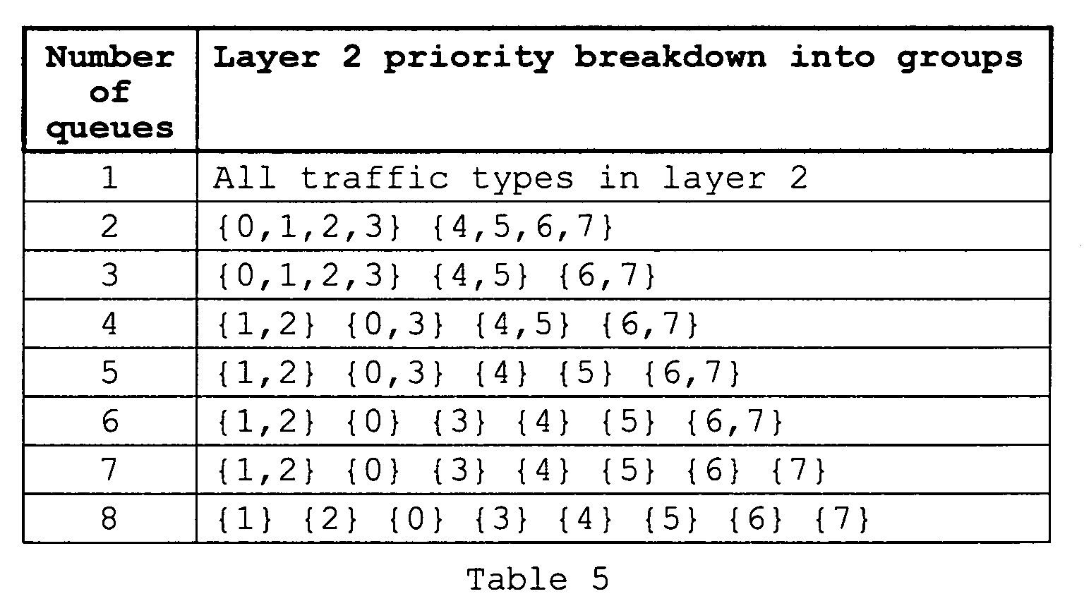
- Table 5 is intended to illustrate the grouping of packets with layer 2 priorities based on the different number of queues maintained by the server.
- each queue then may be serviced as described above with respect to Table 4, thereby generally favoring service toward a queue storing higher layer 2 priority packets.
- Table 5 provides the same result as the example of Table 4, that is, there are a total of eight queues and each queue stores packets of only one type of layer 2 priority.
- the layer 2 switch may alter over time the association of each different layer 2 priority with a corresponding queue.
- the server may monitor or otherwise be apprised of the load of the network either in part or in whole and, in response to that load, it may dynamically adjust the association of layer 2 priorities with different queues.
- the layer 2 switch at a first time and under a first set of load conditions abides by the packet treatment shown above in Table 5.
- the layer 2 switch maintains a sliding window of traffic analysis, which may be on the order of a few minutes wide and examines, among other things, the loads on different traffic types.
- the layer 2 switch predicts what the loads on different traffic types will be in an upcoming future period of time.
- the sliding window examines a period of load history from which the layer 2 switch predicts the load for an immediately-upcoming time period.
- Such an approach for historic examination and change is sometimes referred to in the art as a change "on the fly," and represents a dynamic alteration of treatment based on some type of observation. Accordingly, assume that at a second time just following the first time for which the sliding window provided its history information, the layer 2 switch abides by the packet treatment shown in the following Table 6, which in some instances are changed from those in Table 5.
- Table 5 splits the layer 2 priority groups evenly into two queues (i.e., one with priorities 0,1,2,3 and the other with priorities 4,5,6,7), while Table 6 shifts the level priority 4 into the lower-priority queue, thereby leaving fewer layer 2 priorities in the higher priority queue (i.e., the lower priority queue containing priorities 0,1,2,3,4 and the upper-priority queue containing priorities 5,6,7).
- Tables 5 and 6 illustrates additional changes in how certain layer 2 priorities are re-assigned to different queues.
- the preferred embodiments provide a method and apparatus to map network packet behaviors applying to multiple flows from one architectural model layer to another architectural model layer.
- the behaviors are indicated in an IP network, using DSCPs to implement the behavior at a layer 3 and priority at layer 2, and there is a mapping between adjacent layers in an TCP/IP network.
- various of the inventive teachings also may apply to mappings between non-adjacent layers, for networks other than TCP/IP, and for other parameters affecting behavior.
- more behaviors could be introduced in Internet Protocol Version 6 ("Ipv6") using the traffic class field and the flow field (totally 28 bits).
- the IP addresses are lengthened from 32 bits to 128 bits.
- packets can be identified as belonging to a particular "flow" so that packets that are part of a multimedia presentation and that need to arrive in "real time” can be provided a higher quality-of-service relative to other customers.
- different flow treatments can be treated according to the preferred embodiments described above.
- the preferred embodiments provide numerous benefits. As one benefit, the implementation is fairly straightforward. As another benefit, the preferred embodiments are scalable to add new DSCPs, while it is not necessary to separately configure each edge router. As still another benefit, the inventive teachings may apply to different behaviors and protocol, as mentioned above. In all events, the preceding as well as other benefits should be appreciated by one skilled in the art. Indeed, as a final benefit, while the preferred embodiments have been described in detail, various substitutions, modifications or alterations could be made to the descriptions set forth above without departing from the inventive scope which is defined by the following claims.
Landscapes
- Engineering & Computer Science (AREA)
- Computer Networks & Wireless Communication (AREA)
- Signal Processing (AREA)
- Computer Security & Cryptography (AREA)
- Quality & Reliability (AREA)
- Data Exchanges In Wide-Area Networks (AREA)
- Small-Scale Networks (AREA)
Abstract
Description



Claims (10)
- A network system, comprising:wherein the centralized manager is programmed to perform the step of communicating mapping information to each of the plurality of routers; anda network having a an architectural model comprising a plurality of layers;a centralized manager node, coupled to the network;a plurality of routers coupled to the network for communicating packets along the network and coupled to communicate with the centralized manager node;
wherein the mapping information comprises a correspondence of a behavior on a first of the plurality of layers with a behavior on a second of the plurality of layers. - The system of claim 1 wherein the first of the plurality of layers is adjacent the second of the plurality of layers.
- The system of claim 1:
wherein the network comprises a TCP/IP network; and
wherein the behavior on the first of the plurality of layers comprises a behavior corresponding to a differentiated services control point. - The system of claim 1 wherein the behavior on the second of the plurality of layers comprises a behavior corresponding to a priority.
- The system of claim 1:
wherein the network comprises a TCP/IP network; and
wherein the first of the plurality of layers comprises layer 3 of the TCP/IP network; and
wherein the second of the plurality of layers comprises layer 2 of the TCP/IP network. - The system of claim 5 wherein the first of the plurality of layers is higher than the second of the plurality of layers in the architectural model, and further comprising circuitry operable at the second of the plurality of layers, comprising:a plurality of queues; andcircuitry for assigning a packet, mapped in response to the mapping information, into one of the plurality of queues in response to the correspondence of a behavior on the first of the plurality of layers with a behavior on the second of the plurality of layers.
- The system of claim 6:
wherein the mapping information comprises a plurality of correspondences, each of the correspondences of a behavior on the first of the plurality of layers with a behavior on the second of the plurality of layers; and
wherein the circuitry for assigning assigns selected packets, mapped in response to the mapping information, into a same one of the plurality of queues wherein the selected packets have different respective correspondences of a behavior on the first of the plurality of layers with a behavior on the second of the plurality of layers. - The system of claim 5 and further comprising circuitry operable at the second of the plurality of layers, comprising:a plurality of queues; andcircuitry for assigning a first packet in a first instance, mapped in response to the mapping information, into a first queue of the plurality of queues, in response to the correspondence of a behavior on the first of the plurality of layers with a behavior on the second of the plurality of layers; andcircuitry for assigning a second packet in a second instance, mapped in response to the mapping information, into a second queue of the plurality of queues and that is different from the first queue, in response to the correspondence of a behavior on the first of the plurality of layers with a behavior on the second of the plurality of layers.
- The system of claim 8 wherein the circuitry for assigning assigns the packet in the first instance and the packet in the second instance in response to changes in traffic load on the network.
- A centralized manager node for coupling to a network, the network having an architectural model comprising a plurality of layers and a plurality of routers coupled to the network for communicating packets along the network and coupled to communicate with the centralized manager node, the centralized manager node programmed to perform the steps of:wherein the mapping information comprises a correspondence of a behavior on a first of the plurality of layers with a behavior on a second of the plurality of layers.receiving a request from each of the plurality of routers; andresponsive to each request from a corresponding one of the plurality of routers, communicating mapping information to the requesting router; and
Applications Claiming Priority (2)
| Application Number | Priority Date | Filing Date | Title |
|---|---|---|---|
| US317686 | 2002-12-12 | ||
| US10/317,686 US7773624B2 (en) | 2002-12-12 | 2002-12-12 | Network system and method with centralized flow behavioral mapping between layers |
Publications (2)
| Publication Number | Publication Date |
|---|---|
| EP1429498A2 true EP1429498A2 (en) | 2004-06-16 |
| EP1429498A3 EP1429498A3 (en) | 2008-10-08 |
Family
ID=32325948
Family Applications (1)
| Application Number | Title | Priority Date | Filing Date |
|---|---|---|---|
| EP03026349A Withdrawn EP1429498A3 (en) | 2002-12-12 | 2003-11-18 | Network system and method with centralized flow behavioral mapping between layers |
Country Status (2)
| Country | Link |
|---|---|
| US (1) | US7773624B2 (en) |
| EP (1) | EP1429498A3 (en) |
Families Citing this family (21)
| Publication number | Priority date | Publication date | Assignee | Title |
|---|---|---|---|---|
| US20050021718A1 (en) * | 2003-05-09 | 2005-01-27 | Palliser Networks, Inc. | Centrally managed differentiated service |
| US20050180426A1 (en) * | 2004-02-18 | 2005-08-18 | Yoshifumi Sakata | Network resource-reserving apparatus and method |
| US7958252B2 (en) * | 2004-05-04 | 2011-06-07 | Qualcomm Incorporated | System for scalable transmission of content in a data network |
| US8009668B2 (en) * | 2004-08-17 | 2011-08-30 | Hewlett-Packard Development Company, L.P. | Method and apparatus for router aggregation |
| KR100782840B1 (en) * | 2006-02-23 | 2007-12-06 | 삼성전자주식회사 | Method and Apparatus for transmitting data on PLC network by classifying data |
| US7668177B1 (en) * | 2006-12-28 | 2010-02-23 | Qlogic, Corporation | Method and system for quality of service in host bus adapters |
| US11316688B2 (en) | 2006-12-29 | 2022-04-26 | Kip Prod P1 Lp | Multi-services application gateway and system employing the same |
| WO2008085206A2 (en) | 2006-12-29 | 2008-07-17 | Prodea Systems, Inc. | Subscription management of applications and services provided through user premises gateway devices |
| US9569587B2 (en) | 2006-12-29 | 2017-02-14 | Kip Prod Pi Lp | Multi-services application gateway and system employing the same |
| US20170344703A1 (en) | 2006-12-29 | 2017-11-30 | Kip Prod P1 Lp | Multi-services application gateway and system employing the same |
| US9602880B2 (en) | 2006-12-29 | 2017-03-21 | Kip Prod P1 Lp | Display inserts, overlays, and graphical user interfaces for multimedia systems |
| US11783925B2 (en) | 2006-12-29 | 2023-10-10 | Kip Prod P1 Lp | Multi-services application gateway and system employing the same |
| US8422397B2 (en) * | 2007-12-28 | 2013-04-16 | Prodea Systems, Inc. | Method and apparatus for rapid session routing |
| US8240331B2 (en) * | 2008-10-16 | 2012-08-14 | Honeywell International Inc. | Negative pressure relief valve assembly |
| US8358590B2 (en) * | 2010-12-29 | 2013-01-22 | General Electric Company | System and method for dynamic data management in a wireless network |
| US8422463B2 (en) | 2010-12-29 | 2013-04-16 | General Electric Company | System and method for dynamic data management in a wireless network |
| US8422464B2 (en) | 2010-12-29 | 2013-04-16 | General Electric Company | System and method for dynamic data management in a wireless network |
| JP2016520808A (en) * | 2013-03-15 | 2016-07-14 | アイポジ インコーポレイテッドIposi,Inc. | Indoor location using packet synchronous receiver array |
| US9660878B2 (en) * | 2014-03-14 | 2017-05-23 | International Business Machines Corporation | Managing fabric priorities across heterogeneous server platforms |
| US9538545B2 (en) * | 2014-11-04 | 2017-01-03 | Qualcomm Incorporated | Mapping data traffic throughout protocol layers based on priority information |
| CN113259260B (en) * | 2020-02-11 | 2025-05-23 | 华为云计算技术有限公司 | Method and device for deploying application instance and scheduling application instance |
Family Cites Families (7)
| Publication number | Priority date | Publication date | Assignee | Title |
|---|---|---|---|---|
| US6115378A (en) * | 1997-06-30 | 2000-09-05 | Sun Microsystems, Inc. | Multi-layer distributed network element |
| JP3816246B2 (en) * | 1998-10-30 | 2006-08-30 | 株式会社東芝 | Cut-through path control method |
| EP1111862A1 (en) * | 1999-12-23 | 2001-06-27 | TELEFONAKTIEBOLAGET LM ERICSSON (publ) | Method and devices to provide a defined quality of service in a packet switched communication network |
| US20030007485A1 (en) * | 2001-05-22 | 2003-01-09 | Motorola, Inc | Method and system for operating an edge router |
| US6996110B1 (en) * | 2001-08-31 | 2006-02-07 | 3Com Corporation | Distributed MPLS architecture |
| US7085236B2 (en) * | 2002-05-20 | 2006-08-01 | University Of Massachusetts, Amherst | Active queue management for differentiated services |
| US7376125B1 (en) * | 2002-06-04 | 2008-05-20 | Fortinet, Inc. | Service processing switch |
-
2002
- 2002-12-12 US US10/317,686 patent/US7773624B2/en not_active Expired - Fee Related
-
2003
- 2003-11-18 EP EP03026349A patent/EP1429498A3/en not_active Withdrawn
Non-Patent Citations (1)
| Title |
|---|
| None |
Also Published As
| Publication number | Publication date |
|---|---|
| US20040114608A1 (en) | 2004-06-17 |
| EP1429498A3 (en) | 2008-10-08 |
| US7773624B2 (en) | 2010-08-10 |
Similar Documents
| Publication | Publication Date | Title |
|---|---|---|
| US7773624B2 (en) | Network system and method with centralized flow behavioral mapping between layers | |
| US8199773B2 (en) | Method and apparatus for assigning and allocating network resources to packet-based virtual private networks | |
| JP4213972B2 (en) | Method and apparatus for network path configuration | |
| US6944169B1 (en) | Method and apparatus for managing quality of service in network devices | |
| US6854013B2 (en) | Method and apparatus for optimizing network service | |
| US6822940B1 (en) | Method and apparatus for adapting enforcement of network quality of service policies based on feedback about network conditions | |
| JP4490956B2 (en) | Policy-based quality of service | |
| US7327681B2 (en) | Admission control method in internet differentiated service network | |
| US7185073B1 (en) | Method and apparatus for defining and implementing high-level quality of service policies in computer networks | |
| US7936762B2 (en) | QOS provisioning in a network having dynamic link states | |
| US8571048B2 (en) | Dynamic memory queue depth algorithm | |
| EP1825637B1 (en) | Network centric quality of service using active network technology | |
| EP1035751A2 (en) | Adaptive routing system and method for Qos packet networks | |
| JP2003060691A (en) | Method and apparatus for allocating resources in network router and exchange | |
| KR101471217B1 (en) | Passband reservation system for different traffic classes | |
| JP2000312226A (en) | How to guarantee communication quality | |
| US20050041599A1 (en) | Method and apparatus for maintaining consistent per-hop forwarding behavior in a network using network-wide per-hop behavior definitions | |
| JP2003524994A (en) | Method and apparatus for controlling internet protocol traffic in a WAN or LAN | |
| US7154851B1 (en) | Application-aware resource reservation in multiservice networks | |
| JP2008541553A (en) | Method and configuration in a data network for bandwidth management | |
| Pinto et al. | Lightweight admission control and traffic management with SDN | |
| EP4531365A1 (en) | Network-to-endpoint communication for topology-aware multi-path transport protocols | |
| Maniyeri et al. | A Linux based software router supporting QoS, policy based control and mobility | |
| Follows et al. | Application-Driven Networking: Class of Service in IP, Ethernet and ATM Networks | |
| JP2001230815A (en) | Communication packet length control method and packet switch in packet switching network |
Legal Events
| Date | Code | Title | Description |
|---|---|---|---|
| PUAI | Public reference made under article 153(3) epc to a published international application that has entered the european phase |
Free format text: ORIGINAL CODE: 0009012 |
|
| AK | Designated contracting states |
Kind code of ref document: A2 Designated state(s): AT BE BG CH CY CZ DE DK EE ES FI FR GB GR HU IE IT LI LU MC NL PT RO SE SI SK TR |
|
| AX | Request for extension of the european patent |
Extension state: AL LT LV MK |
|
| RAP1 | Party data changed (applicant data changed or rights of an application transferred) |
Owner name: ALCATEL LUCENT |
|
| PUAL | Search report despatched |
Free format text: ORIGINAL CODE: 0009013 |
|
| AK | Designated contracting states |
Kind code of ref document: A3 Designated state(s): AT BE BG CH CY CZ DE DK EE ES FI FR GB GR HU IE IT LI LU MC NL PT RO SE SI SK TR |
|
| AX | Request for extension of the european patent |
Extension state: AL LT LV MK |
|
| 17P | Request for examination filed |
Effective date: 20090402 |
|
| AKX | Designation fees paid |
Designated state(s): AT BE BG CH CY CZ DE DK EE ES FI FR GB GR HU IE IT LI LU MC NL PT RO SE SI SK TR |
|
| 17Q | First examination report despatched |
Effective date: 20090723 |
|
| RAP1 | Party data changed (applicant data changed or rights of an application transferred) |
Owner name: ALCATEL LUCENT |
|
| 111Z | Information provided on other rights and legal means of execution |
Free format text: AT BE BG CH CY CZ DE DK EE ES FI FR GB GR HU IE IT LI LU MC NL PT RO SE SI SK TR Effective date: 20130410 |
|
| RAP1 | Party data changed (applicant data changed or rights of an application transferred) |
Owner name: ALCATEL LUCENT |
|
| D11X | Information provided on other rights and legal means of execution (deleted) | ||
| STAA | Information on the status of an ep patent application or granted ep patent |
Free format text: STATUS: THE APPLICATION IS DEEMED TO BE WITHDRAWN |
|
| 18D | Application deemed to be withdrawn |
Effective date: 20150602 |