EP1429449A1 - Torque stabilizer for brushless servo motor - Google Patents
Torque stabilizer for brushless servo motor Download PDFInfo
- Publication number
- EP1429449A1 EP1429449A1 EP01967711A EP01967711A EP1429449A1 EP 1429449 A1 EP1429449 A1 EP 1429449A1 EP 01967711 A EP01967711 A EP 01967711A EP 01967711 A EP01967711 A EP 01967711A EP 1429449 A1 EP1429449 A1 EP 1429449A1
- Authority
- EP
- European Patent Office
- Prior art keywords
- servo motor
- brushless servo
- phase
- computing section
- torque
- Prior art date
- Legal status (The legal status is an assumption and is not a legal conclusion. Google has not performed a legal analysis and makes no representation as to the accuracy of the status listed.)
- Granted
Links
Images


Classifications
-
- H—ELECTRICITY
- H02—GENERATION; CONVERSION OR DISTRIBUTION OF ELECTRIC POWER
- H02P—CONTROL OR REGULATION OF ELECTRIC MOTORS, ELECTRIC GENERATORS OR DYNAMO-ELECTRIC CONVERTERS; CONTROLLING TRANSFORMERS, REACTORS OR CHOKE COILS
- H02P6/00—Arrangements for controlling synchronous motors or other dynamo-electric motors using electronic commutation dependent on the rotor position; Electronic commutators therefor
- H02P6/10—Arrangements for controlling torque ripple, e.g. providing reduced torque ripple
-
- H—ELECTRICITY
- H02—GENERATION; CONVERSION OR DISTRIBUTION OF ELECTRIC POWER
- H02P—CONTROL OR REGULATION OF ELECTRIC MOTORS, ELECTRIC GENERATORS OR DYNAMO-ELECTRIC CONVERTERS; CONTROLLING TRANSFORMERS, REACTORS OR CHOKE COILS
- H02P6/00—Arrangements for controlling synchronous motors or other dynamo-electric motors using electronic commutation dependent on the rotor position; Electronic commutators therefor
- H02P6/24—Arrangements for stopping
Definitions
- the present invention relates to a device for stabilizing torque of a brushless servo motor used as a driving source such as a throttle valve, an actuator, an exhaust gas recirculation (hereinafter referred to as EGR) valve and the like.
- a driving source such as a throttle valve, an actuator, an exhaust gas recirculation (hereinafter referred to as EGR) valve and the like.
- EGR exhaust gas recirculation
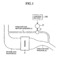
- Fig. 1 is an explanatory diagram in which a valve 11 of the EGR valve arranged in an exhaust gas return passage (c) for making an exhaust gas passage (a) of an engine E communicate with an intake gas passage (b) thereof is an object to be controlled and in which a brushless servo motor 21 is driven by an output of a control section 100 to control an opening of the valve 11.
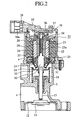
- Fig. 2 is a longitudinal cross sectional view to show a constitution of the EGR valve having the brushless servo motor 21 as a driving source to which a servo control device is applied.
- a reference numeral 1 denotes a valve body in which a passage communicating with the exhaust gas return passage (c) disposed in a recirculation system of an exhaust gas is formed.
- a reference numeral 21 denotes a brushless servo motor to be a driving means (torque generating source) of a valve for opening/closing the exhaust gas passage
- 22 denotes a motor case mounted on the valve body 1
- 23 denotes a rotor rotatably supported in the motor case 22 via bearings 24, 25, and the rotor 23 has a screw hole 23a which is made through a central portion of a shaft.
- a reference numeral 26 denotes a magnet mounted on an outer peripheral portion of the rotor 3
- 27 denotes a stator core surrounding an outer periphery of the magnet 26, and between this stator core 27 and the above mentioned magnet 26 is formed a predetermined gap.
- a reference numeral 28 denotes a coil that is arranged on the stator core 27 and it constitutes a stator
- 29 denotes a motor shaft to be a valve driving shaft
- this motor shaft 29 is made as a screw shaft and screwed into the screw hole 23a of the above mentioned rotor 23 and made to move in an axial direction by a rotation of the above mentioned rotor 23.
- a reference numeral 30 denotes a valve shaft abutting member integrally formed with the motor shaft 29.
- a reference numeral 31 denotes a covering member mounted on an end surface of the valve shaft abutting member 30 side in the motor case 22, 32 denotes a spring retaining member mounted on a tip side of the valve shaft abutting member 30, 33 denotes a spring for urging the valve, which is hung between the spring retaining member 32 and the above mentioned covering member 31, and this spring 33 urges the valve 11 at the tip of the valve shaft 13 via the valve shaft abutting member 30 in a direction that opens the valve 11.
- a reference numeral 14 denotes a spring receiver mounted on the top end of the valve shaft 13 and between the spring receiver 14 and the valve body 1 is provided a return spring 18.
- a reference numeral 35 denotes a power source side case mounted on an opening end portion of the motor case 22.
- This power source side case 35 is an integrally molded part made of synthetic resin and constitutes a main device body for passing a current through the brushless servo motor 21 and is an integral combination of a board 37 for mounting hall devices 36 and an input/output connector part 38 having a connector terminal 38a.
- a reference numeral 39 denotes a magnet that is mounted on an end of the rotor so as to move opposite to the hall device 36.
- Fig. 3 is a control circuit diagram of the brushless servo motor 21 in the prior art.
- the control circuit has hall devices 36U, 36V, 36W for detecting a position of the rotor 23, a switching unit 40 that includes a group of transistors for receiving the signals of these hall devices and switching the passing of a current through coils 28U, 28V, 28W, and passes the current through the coils 28U, 28V, 28W sequentially to thereby rotate the rotor 23 in a given direction.
- the above mentioned switching unit 40 has switching devices (hereinafter referred to as switch devices) 41U, 41V, 41W that receive output signals of the hall devices 36U, 36V, 36W to be brought into conduction; an interrupting section 42 that receives output signals of the switch devices 41U, 41V, 41W to output an interrupting signal; a signal processing block 43 that receives and processes output signals of the above mentioned hall devices 36U, 36V, 36W based on the output signal of the interrupting section 42; switch devices 44 to 49 that receive the output signals of the signal processing block 43 to be brought into conduction; and pairs of switch devices 50 and 51, 52 and 53, 54 and 55 each pair of which are connected in series to each other, have one end of one of coils 28U, 28V, 28W connected to their connection midpoint, and change a state of conduction based on the output signal of the switch devices 44 to 49.
- switch devices hereinafter referred to as switch devices
- the above mentioned signal processing block 43 has a digital input port 61 for receiving the output signals of the hall devices 36U, 36V, 36W; a counter 62 for reading in an output of the digital input port 61; a PI control computing section 64 for performing a PI control computation based on an output signal of the counter 62 and an output signal of a target value determining section 63; an excitation duty computing section for performing an excitation duty computation based on an output signal of the PI control computing section 64; an excitation phase computing section 66 for computing an excitation phase based on an output signal of the excitation duty computing section 65 and an output signal of the digital input port 61; a digital output port 67 for outputting an ON signal based on an output signal of the excitation phase computing section 66; and a PWM output port 68 for outputting a PWM signal based on an output signal of the excitation phase computing section 66 and an output signal of the excitation duty computing section 65.
- the target value determining section 63 determines a target value.
- the PI control computing section 64 performs the PI control computation based on a present value inputted via the counter 62 and a target value from the target value determining section 63, and the excitation duty computing section 65 performs an excitation duty computation based on a result of the PI control computation and outputs a result of the excitation duty computation to the excitation phase computing section 66 and the PWM output port 68.
- the excitation phase computing section 66 performs the excitation phase computation based on the given result of the excitation duty computation and the input signal received via the digital input port 61, and outputs a result of the excitation phase computation to the digital output port 67 and the PWM output port 68.
- the digital output port 67 outputs an ON signal, for example, to a terminal U based on the output signal of the excitation phase computing section 66 to bring the switch device 50 into conduction via the switch device 44 to thereby connect a (+) terminal of the brushless servo motor 21 to a power applying terminal V.
- the PWM output port 51 outputs an output signal, for example, to a terminal W based on the output signals of the excitation duty computing section 65 and the excitation phase computing section 66 to bring the switch device 55 into conduction via the switch device 49 to thereby pass a current in a direction shown by an arrow through the brushless servo motor 21.
- the brushless servo motor 21 is operated to move down the motor shaft 29 by a rotation of its rotor 23 to move the valve shaft 13 in the same direction against the return spring 18 by this down movement, thereby moving the control valve 11 to a target position to open the control valve 11.
- the hall devices 36U, 36V, 36W detect the position of the rotating rotor 23 sequentially and switch a passing of the current through the coils 28U, 28V, 28W to rotate the rotor 23 in the same direction.
- power required to hold the control valve 11 at the position against a restoring force of the return spring 18 is supplied to the brushless servo motor 21 when the control valve 11 moves near to the target position and a difference between the present position and the target value becomes nearly equal to zero.
- the EGR valve is given a predetermined return torque in the direction that closes the control valve 11 by the return spring 18 as an urging means and is given a variable motor torque in the direction that opens the control valve 11 by a rotational torque of the brushless servo motor 21 in a direction against a return torque, thereby holding a state of an expected opening by a balance between these torque.
- Fig. 4 shows torque curves in the respective exciting states when the same current flows in U to V and U to W, and in a case where a current flowing from of the coil U to the coil V is changed to a current flowing from the coil U to the coil W, when the current is changed at a point t1, a continuous torque can be produced, but when the current is changed at a delayed point t2, the torque is greatly varied.
- a movement of the control valve 11 which moves in proportion to time, is made greatly varied near a "point a" as shown in Fig. 4(b).
- the brushless servo motor in the prior art is constituted in the manner described above, when this brushless servo motor is used as a driving source of the EGR valve, in a case where the control valve is held at a predetermined opening position by the torque balance between the return torque and the driving torque of the brushless servo motor 21, there is presented a problem that the torque balance is made unstable by a deviation in detecting the position of the rotor by the hall devices and a condition of load applied to the rotor.
- the present invention has been made to solve the above mentioned problem, and an object of the present invention is to stabilize torque at a predetermined opening (middle holding) position in a brushless servo motor.
- a torque stabilizing device of a brushless servo motor in accordance with the present invention includes: a brushless servo motor for driving a driven body; a hall device of each phase for detecting a position of permanent magnet rotor of the brushless servo motor; a switching unit that receives a detection signal of the hall device to switch the passing of a current through a coil of each phase; a PI control computing section for performing a PI computation based on a detection value of the hall device and a predetermined target value; and an excitation duty computing section for outputting a power source control signal for the brushless servo motor based on an output signal of the PI control computing section, characterized by that a load direction detecting section that detects the driven body moving near to a target position and outputs a signal for stopping switching phase of a current passing through the brushless servomotor to stop switching the phase of the current.
- the load direction detecting section of the torque stabilizing device of a brushless servo motor in accordance with the present invention detects the driven body moving near to the target position by an inversion of polarity of the output signal of the PI control computing section.
- the load direction detecting section of the torque stabilizing device of a brushless servo motor in accordance with the present invention holds a phase of a current passing in a direction that the driven body is pushed by a load.
- Fig. 5 is a control circuit diagram of a brushless servo motor 21 in accordance with embodiment 1.
- a reference numeral 71 denotes a load direction detecting section for checking whether a control valve 11 is in the vicinity of a predetermined opening position. Because a result of the PI control computation by a PI control computing section 64 remains “+” when the control valve 11 is within a predetermined opening position but changes to "-" when the control valve 11 exceeds the predetermined opening position, it can be made sure that the valve is in the vicinity of the predetermined opening position by means that the load direction detecting section 71 detects a point where the result of the PI control computation changes from "+" to "-".
- the other constitution of this embodiment is quite the same as those of the prior art shown in Fig. 3 described above, so the same parts are denoted by the same reference symbols and their further descriptions will be omitted.
- the target value determining section 63 determines a target value.
- the output signal of hall devices 36U, 36V, 36W which detect the position of the rotor 23, brings any one of switch devices 41U, 41V, 41W into conduction and an output signal of the interrupting section 42 receiving a signal of conduction makes the digital input port 61 and the counter 62 start receiving an input signal.
- the PI control computing section 64 performs the PI control computation based on a present value received via the counter 62 and the target value from the target value determining section 63 and the excitation duty computing section 65 performs an excitation duty computation based on the computation result and outputs its computation result to the excitation phase computing section 66 and the PWM output port 68.
- the excitation phase computing section 66 performs an excitation computation based on the given result of the excitation duty computation and an input signal received via the digital input port 61, and outputs its computation result to the digital output port 67 and the PWM output port 68.
- the digital output port 67 outputs an ON signal, for example, to the terminal U based on an output signal of the excitation phase computing section 66 to bring the switch device 50 into conduction via the switch device 44 to thereby connect the (+) terminal of the brushless servo motor 21 to the power applying terminal V.
- the PWM output port 68 outputs an output signal, for example, to the terminal Wbased on the output signals of the excitation duty computing section 65 and the excitation phase computing section 66 to bring the switch device 55 into conduction via the switch device 49 to thereby pass a current in a direction shown by an arrow through the brushless servo motor 21.
- the brushless servo motor 21 is operated to move down the motor shaft 29 by the rotation of its rotor 23 to move the valve shaft 13 in the same direction against the return spring 18 by this down movement, thereby moving the control valve 11 to the target position to open the control valve 11.
- the hall devices 36U, 36V, 36W detect the position of the rotating rotor 23 sequentially and switch the passing of the current through coils 28U, 28V, 28W to rotate the rotor 23 in the same direction, thereby moving the control valve 11 to the vicinity of the target position.
Landscapes
- Engineering & Computer Science (AREA)
- Power Engineering (AREA)
- Control Of Motors That Do Not Use Commutators (AREA)
Abstract
Description
Claims (3)
- A torque stabilizing device of a brushless servo motor comprising:a brushless servo motor (21) for driving a driven body (11) ;a hall device (36U, 36V, 36W) of each phase for detecting a position of permanent magnet rotor of the brushlessservo motor (21);a switching unit (40) that receives a detection signal of the hall device (36U, 36V, 36W) to switch the passing of a current through a coil of each phase;a PI control computing section (64) for performing a PI computation based on a detection value of said hall device (36U, 36V, 36W) and a predetermined target value; andan excitation duty computing section (65) for outputting a power source control signal for said brushless servo motor (21) based on an output signal of the PI control computing section (64), characterized by thata load direction detecting section (71) that detects said driven body (11) moving near to a target position and outputs a signal for stopping switching phase of a current passing through said brushless servo motor (21) to stop switching the phase of the current.
- The torque stabilizing device of a brushless servo motor according to claim 1, characterized by that the load direction detecting section (71) detects the driven body (11) moving near to the target position by an inversion of polarity of the output signal of the PI control computing section (64).
- The torque stabilizing device of a brushless servo motor according to claim 1, characterized by that the load direction detecting section (71) holds a phase of a current passing in a direction that the driven body (11) is pushed by a load.
Applications Claiming Priority (1)
| Application Number | Priority Date | Filing Date | Title |
|---|---|---|---|
| PCT/JP2001/008066 WO2003026124A1 (en) | 2001-09-17 | 2001-09-17 | Torque stabilizer for brushless servo motor |
Publications (3)
| Publication Number | Publication Date |
|---|---|
| EP1429449A1 true EP1429449A1 (en) | 2004-06-16 |
| EP1429449A4 EP1429449A4 (en) | 2010-06-16 |
| EP1429449B1 EP1429449B1 (en) | 2017-03-01 |
Family
ID=11737733
Family Applications (1)
| Application Number | Title | Priority Date | Filing Date |
|---|---|---|---|
| EP01967711.1A Expired - Lifetime EP1429449B1 (en) | 2001-09-17 | 2001-09-17 | Torque stabilizer for brushless servo motor |
Country Status (4)
| Country | Link |
|---|---|
| US (1) | US6737771B2 (en) |
| EP (1) | EP1429449B1 (en) |
| JP (1) | JP4271032B2 (en) |
| WO (1) | WO2003026124A1 (en) |
Families Citing this family (10)
| Publication number | Priority date | Publication date | Assignee | Title |
|---|---|---|---|---|
| JP4531359B2 (en) * | 2003-07-18 | 2010-08-25 | 三菱電機株式会社 | motor |
| JP4367204B2 (en) * | 2004-03-31 | 2009-11-18 | 株式会社デンソー | Synchronous brushless motor device |
| US7345389B2 (en) * | 2004-05-24 | 2008-03-18 | Alps Electric Co., Ltd. | Motor, motor having encoder, and multi-direction input device |
| TWI302780B (en) * | 2005-05-27 | 2008-11-01 | Delta Electronics Inc | Motor mechanism with two-direction buffering function |
| TWI319256B (en) * | 2005-06-30 | 2010-01-01 | Delta Electronics Inc | Motor mechanism |
| US20070145838A1 (en) * | 2005-12-07 | 2007-06-28 | Nidec Corporation | Motor and Method of Manufacturing Housing |
| DE112007003276T5 (en) * | 2007-03-16 | 2010-02-11 | Mitsubishi Electric Corp. | Brushless motor unit |
| US8766578B2 (en) | 2012-02-27 | 2014-07-01 | Canadian Space Agency | Method and apparatus for high velocity ripple suppression of brushless DC motors having limited drive/amplifier bandwidth |
| DE102012110656B4 (en) * | 2012-11-07 | 2026-03-26 | Dr. Ing. H.C. F. Porsche Aktiengesellschaft | Stabilizer assembly for the chassis of a motor vehicle |
| DE102013020427B4 (en) * | 2013-01-31 | 2018-04-05 | Makita Corporation | Working machine with operating staff |
Family Cites Families (14)
| Publication number | Priority date | Publication date | Assignee | Title |
|---|---|---|---|---|
| US3876919A (en) * | 1970-06-08 | 1975-04-08 | Robert W Kearns | Structure for and method of surface condition sensing and indicating and motor speed control |
| US4025808A (en) * | 1975-07-21 | 1977-05-24 | Barber-Colman Company | Commutating machine with integral speed control |
| US4591774A (en) * | 1981-05-21 | 1986-05-27 | Dataproducts Corporation | High performance incremental motion system using a closed loop stepping motor |
| JP2777714B2 (en) | 1987-09-03 | 1998-07-23 | トヨタ自動車株式会社 | Control device for brushless motor |
| EP0413849A1 (en) * | 1989-08-25 | 1991-02-27 | Siemens Aktiengesellschaft | Rotation detection device for a commutator motor excited by permanent magnets or protruding poles |
| JP3243884B2 (en) * | 1992-05-27 | 2002-01-07 | 国産電機株式会社 | Brushless motor and its stopping method |
| JPH06339252A (en) * | 1993-05-27 | 1994-12-06 | Mabuchi Motor Co Ltd | Rotation detecting device for small dc motor |
| TW328190B (en) * | 1994-06-14 | 1998-03-11 | Toshiba Co Ltd | Control device of brushless motor and method of fault detection and air conditioner |
| DE19518991A1 (en) * | 1994-11-21 | 1997-01-23 | Papst Motoren Gmbh & Co Kg | Operating method for electronically commutated motor e.g. for motor vehicle idling flap control |
| GB9601753D0 (en) | 1996-01-29 | 1996-03-27 | Switched Reluctance Drives Ltd | Dual mode position control systems with speed profiling |
| DE19815964B4 (en) | 1998-04-09 | 2008-09-25 | Dr. Fritz Faulhaber Gmbh & Co. Kg | electric motor |
| JP4269380B2 (en) * | 1999-01-11 | 2009-05-27 | ソニー株式会社 | Motor drive circuit and disk device |
| JP2001037281A (en) * | 1999-05-18 | 2001-02-09 | Matsushita Electric Ind Co Ltd | Motor torque control device |
| DE19924631A1 (en) * | 1999-05-29 | 2000-11-30 | Bosch Gmbh Robert | Commutator motor |
-
2001
- 2001-09-17 JP JP2003529620A patent/JP4271032B2/en not_active Expired - Fee Related
- 2001-09-17 EP EP01967711.1A patent/EP1429449B1/en not_active Expired - Lifetime
- 2001-09-17 US US10/416,888 patent/US6737771B2/en not_active Expired - Lifetime
- 2001-09-17 WO PCT/JP2001/008066 patent/WO2003026124A1/en not_active Ceased
Also Published As
| Publication number | Publication date |
|---|---|
| JP4271032B2 (en) | 2009-06-03 |
| US6737771B2 (en) | 2004-05-18 |
| EP1429449B1 (en) | 2017-03-01 |
| US20040036429A1 (en) | 2004-02-26 |
| WO2003026124A1 (en) | 2003-03-27 |
| EP1429449A4 (en) | 2010-06-16 |
| JPWO2003026124A1 (en) | 2005-01-06 |
Similar Documents
| Publication | Publication Date | Title |
|---|---|---|
| US7143743B2 (en) | Valve position controller | |
| EP1429449A1 (en) | Torque stabilizer for brushless servo motor | |
| KR100985946B1 (en) | Brushless motor device and method | |
| JP4401926B2 (en) | Relative position detection control device and saddle riding type vehicle | |
| US6465974B2 (en) | Air intake amount control apparatus for an engine | |
| WO2009110206A1 (en) | Brushless motor device and control device | |
| JP3543896B2 (en) | Engine intake air control system | |
| WO2016162924A1 (en) | Actuator controller, actuator, valve driving device, and actuator abnormality detection method | |
| US6913122B2 (en) | Brake for DC motor | |
| US6836091B2 (en) | Servo control device of DC motor | |
| JPH0993799A (en) | Drive control device for rotating body | |
| JP2024034436A (en) | System and method for controlling a stepper motor | |
| JP2727659B2 (en) | Operating amount information output device | |
| WO2002014675A1 (en) | Controller for exhaust gas recirculation valve | |
| FI4203295T3 (en) | Electric motor for a positioning or conveying device of a motor vehicle | |
| KR100305780B1 (en) | Idle speed actuator for vehicle | |
| JPS6362981A (en) | Rotary solenoid type actuator | |
| JP2000060176A (en) | Brushless motor driving device and brushless motor | |
| JPWO2002014675A1 (en) | Exhaust gas recirculation valve control device |
Legal Events
| Date | Code | Title | Description |
|---|---|---|---|
| PUAI | Public reference made under article 153(3) epc to a published international application that has entered the european phase |
Free format text: ORIGINAL CODE: 0009012 |
|
| 17P | Request for examination filed |
Effective date: 20030507 |
|
| AK | Designated contracting states |
Kind code of ref document: A1 Designated state(s): AT BE CH CY DE DK ES FI FR GB GR IE IT LI LU MC NL PT SE TR |
|
| RAP1 | Party data changed (applicant data changed or rights of an application transferred) |
Owner name: MITSUBISHI DENKI KABUSHIKI KAISHA |
|
| A4 | Supplementary search report drawn up and despatched |
Effective date: 20100519 |
|
| 17Q | First examination report despatched |
Effective date: 20101102 |
|
| RIC1 | Information provided on ipc code assigned before grant |
Ipc: H02P 6/10 20060101ALI20160808BHEP Ipc: H02P 6/24 20060101AFI20160808BHEP |
|
| GRAP | Despatch of communication of intention to grant a patent |
Free format text: ORIGINAL CODE: EPIDOSNIGR1 |
|
| INTG | Intention to grant announced |
Effective date: 20160919 |
|
| GRAS | Grant fee paid |
Free format text: ORIGINAL CODE: EPIDOSNIGR3 |
|
| GRAA | (expected) grant |
Free format text: ORIGINAL CODE: 0009210 |
|
| RBV | Designated contracting states (corrected) |
Designated state(s): DE |
|
| AK | Designated contracting states |
Kind code of ref document: B1 Designated state(s): DE |
|
| REG | Reference to a national code |
Ref country code: DE Ref legal event code: R096 Ref document number: 60150336 Country of ref document: DE |
|
| REG | Reference to a national code |
Ref country code: DE Ref legal event code: R097 Ref document number: 60150336 Country of ref document: DE |
|
| PLBE | No opposition filed within time limit |
Free format text: ORIGINAL CODE: 0009261 |
|
| STAA | Information on the status of an ep patent application or granted ep patent |
Free format text: STATUS: NO OPPOSITION FILED WITHIN TIME LIMIT |
|
| 26N | No opposition filed |
Effective date: 20171204 |
|
| PGFP | Annual fee paid to national office [announced via postgrant information from national office to epo] |
Ref country code: DE Payment date: 20200901 Year of fee payment: 20 |
|
| REG | Reference to a national code |
Ref country code: DE Ref legal event code: R071 Ref document number: 60150336 Country of ref document: DE |