EP1429399A2 - Superconducting wire rod and method of producing the same - Google Patents
Superconducting wire rod and method of producing the same Download PDFInfo
- Publication number
- EP1429399A2 EP1429399A2 EP03018935A EP03018935A EP1429399A2 EP 1429399 A2 EP1429399 A2 EP 1429399A2 EP 03018935 A EP03018935 A EP 03018935A EP 03018935 A EP03018935 A EP 03018935A EP 1429399 A2 EP1429399 A2 EP 1429399A2
- Authority
- EP
- European Patent Office
- Prior art keywords
- wire rod
- superconducting
- superconducting wire
- superconductor
- equal
- Prior art date
- Legal status (The legal status is an assumption and is not a legal conclusion. Google has not performed a legal analysis and makes no representation as to the accuracy of the status listed.)
- Withdrawn
Links
Images




Classifications
-
- H—ELECTRICITY
- H10—SEMICONDUCTOR DEVICES; ELECTRIC SOLID-STATE DEVICES NOT OTHERWISE PROVIDED FOR
- H10N—ELECTRIC SOLID-STATE DEVICES NOT OTHERWISE PROVIDED FOR
- H10N60/00—Superconducting devices
- H10N60/20—Permanent superconducting devices
- H10N60/202—Permanent superconducting devices comprising metal borides, e.g. MgB2
-
- H—ELECTRICITY
- H10—SEMICONDUCTOR DEVICES; ELECTRIC SOLID-STATE DEVICES NOT OTHERWISE PROVIDED FOR
- H10N—ELECTRIC SOLID-STATE DEVICES NOT OTHERWISE PROVIDED FOR
- H10N60/00—Superconducting devices
- H10N60/01—Manufacture or treatment
- H10N60/0856—Manufacture or treatment of devices comprising metal borides, e.g. MgB2
Definitions
- the present invention relates to a super-conducting wire rod in which a high superconducting critical current density can be obtained by using a superconducting material expressing a superconductivity under an environment below a critical temperature, a method of producing the superconducting wire rod, and a superconducting magnet using the superconducting wire rod.
- the present invention relates to a superconducting wire rod which is applied to a current lead, an electric power transmission cable, a large size magnet, a nuclear magnetic resonance analyzing apparatus, a medical magnetic resonance diagnosing apparatus, a superconducting electric power storage apparatus, a magnetic separating apparatus, a magnetic single crystal pulling apparatus, a refrigerator cooling superconducting magnet apparatus, a superconducting energy storage, a superconducting generator, a magnet for nuclear fusion reactor, and the like.
- the superconducting material there has been known metals such as a niobium titanium (NbTi), a niobium tin (Nb 3 Sn) and the like.
- NbTi niobium titanium
- Nb 3 Sn niobium tin
- these superconductive metals have a problem that it is necessary to use an expensive liquid helium for cooling, because a critical temperature is low, for example, the critical temperature is 23 K (Kelvin) even in a niobium germanium (Nb 3 Ge) having the highest critical temperature.
- this material Since this material has an extremely small magnetic field anisotropy, a practical critical current density can be obtained without necessity of aligning a crystal orientation with a substrate as in the copper oxide. Further, the inventors of the present application make it appear that this material is extremely excellent in a bending property, and a critical current density equal to or more than 90% can be maintained with respect to a wire rod with no strain even when a strain of 1.5% is applied to the superconducting wire.
- a critical temperature is 20 K or more higher than that of the metal superconducting material, or a report that the critical magnetic field is about 20 T in a normal tape wire, and about 40 T in a thin film, as described in a non-patent document 2 (cond-mat/0108265). It is considered that an application in a strong magnetic field is practical by using these properties.
- the practical superconducting property can be maintained by the MgB 2 group wire rod, it can be expected to contribute to various fields, for example, an application to a biological science which is one of fields in the spotlight in recent years, in addition to a power application such as an electric power transmission cable or the like.
- the MgB 2 group superconducting wire rod which has been produced by way of trial has a problem that a critical current density, an upper critical magnetic field and an irreversible magnetic field are low in comparison with the conventional metal group and the oxide group superconductor.
- the critical current density a value over 10 5 A/cm 2 in a temperature range equal to or less than 20 K is reported in a short wire rod of some cm order, however, in a long wire rod of some m order, the performance can not be maintained, and the critical current density is about single-digit lowered in comparison with the short wire rod. Accordingly, particularly considering a practical use using the long wire rod, it is necessary to widely improve the critical current density.
- an object of the present invention is to provide a superconducting wire rod which is filled with or interiorly includes a superconductor containing a boron, wherein the superconducting wire rod has a practical critical electric density even under a magnetic field, and a method of producing the superconducting wire rod.
- the inventors of the present invention have advanced research and development for the purpose of aiming mainly to an application of an oxide superconductor and a magnet using the oxide superconductor. During this step, it has been clarified that the following four items are particularly important as items for improving a critical current density.
- a superconducting wire rod having a high property can be obtained by simultaneously achieving the four items mentioned above.
- the critical current density is not a specific value for the material, but depends widely upon a producing method. Accordingly, it is known that the critical current density is not so improved only by the oxide superconducting metal rod or the method which has been applied to the metal group superconducting wire rod. That is, it is necessary to optimize the critical current density in correspondence to the material, and it is necessary to make an independent consideration in the superconductor containing the boron.
- the inventors of the present invention have paid attention to solving the problems mentioned above.
- the inventors of the present invention has found a novel superconducting wire rod and a method of producing the novel superconducting wire, which can widely improve a superconducting property in comparison with the conventional superconducting wire rod and the conventional superconducting coil using the long wire rod.
- the object mentioned above can be achieved by a superconducting wire rod filled with or interiorly including a superconductor containing a boron, in which a metal powder is added to a superconducting material included in the super-conducting wire rod, an element of the metal powder is selected from at least one of an indium, a tin, a lead, an iron, a magnesium and an aluminum, the metal power having an average grain diameter equal to or less than 20 ⁇ m is 5 to 25 vol% dispersed in the superconducting material, a density of the superconducting material included in the superconducting wire rod after a final work is equal to or more than 90% a theoretical density, and a critical current density is equal to or more than 1000 A/cm 2 .
- the object mentioned above can be achieved by a superconducting wire rod in which a defect portion having an area equal to or more than 10 mm 2 does not exist over an entire length of the wire rod, on a surface of the superconducting wire rod.
- the object mentioned above can be achieved by a superconducting wire rod having a cross section structure in which the superconductor containing the boron is made complex compound with a different kind of superconductor.
- the different kind of superconductor other than the superconductor containing the boron is a niobium titanium, a more effect can be obtained.
- connection between the superconducting wire rods mentioned above can be achieved by using a connecting method corresponding to a bonding via the superconductor containing the boron.
- a method of producing a superconducting wire rod comprising:
- the superconducting wire rod having an excellent critical current property in comparison with the conventional metal group superconducting wire rod in the magnetic field and in a temperature range over 20 K, by employing a method of producing a superconducting wire rod including a step of making the reduced metal pipe composite with different superconductor.
- a method of producing a superconductor, a sintered body or an agglomerate in the present invention there can be listed up a method of crushing and mixing the respective chemical compounds and sintering the mixture.
- This method includes a method of mixing all the raw material chemical compounds at one time, and a method of previously mixing a part of the raw material chemical compounds and thereafter mixing the remaining raw material powders. At this time, it is effective to add the metal powder of 5 to 25 vol%.
- the metal powder is a metal powder which is selected from at least one of an indium, a tin, a lead, an iron, a magnesium and an aluminum.
- a temperature of heat treatment for combining the superconducting powders in the present invention employs a temperature within a range between 400 and 1200°C. Further, the heat treatment is carried out by using an oxygen gas, a nitrogen gas, an argon gas, a hydrogen gas or the like independently or a mixture thereof, as occasion demands. Further, the heat treatment is carried out while pressurizing under a pressure equal to or more than an atmospheric pressure, as occasion demands.
- the metal coating member employs one or more selected from a silver, an aluminum, a copper, an iron, a platinum, a palladium, a nickel, a stainless, a chrome, a magnesium, a tantalum, a niobium, a titan, a tin, a beryllium, a tungsten and a cobalt.
- a copper-aluminum alloy (an arms bronze) may be an effective metal coating member. It goes without saying that the metal coating member does not thermally react with the superconductor, and it is further necessary to have a good workability in view of a mass production.
- the wire rod so as to have multiple cores, a plurality of metal coating members are arranged, however, the kind and the material can be made different.
- the coating member has a dual structure
- the metal coating members in an inner side and an outer side are made of a material which is not thermally reacted with the superconductor, however, it is more desirable that the outer metal coating member is made of a material which has a high strength in addition to the property concerning the reaction. Accordingly, there is an advantage that the metal coating member can serve both as a coating member and a reinforcing member. Further, in the case that an insulating film such as an oxygen film or the like is formed on a surface of the metal, it is possible to play a part of the insulating member.
- the diameter reducing work of the wire rod is achieved by repeatedly carrying out a wire drawing work in which a reduction in area per 1 pass is about 1 to 20%, by using a drawing bench, a swager, a cassette roller die or a grooved roll.
- the wire rod is made so as to have multiple cores, however, a method of making the wire rod so as to have multiple cores is achieved by assembling the wire rod wire drawn in a round cross sectional shape or a hexagonal cross sectional shape in the pipe, and wire drawing to a predetermined wire diameter with a reduction in area per 1 pass being about 1 to 20%, by using the apparatus mentioned above.
- the process in this case has an effect of densifying a superconducting powder charged within the metal coating material as well as forming the wire rod in a desired shape. Further, in order to intend to densify further, a wire rod having a high critical current density can be obtained by working by a cold rolling mill or a hot rolling mill, forming a planer or a tape-like cross section and heat treating under a suitable temperature or atmosphere.
- the wire rod having a high critical current density in the case that the density of the superconductor worked in the final shape is equal to or more than 90% of a theoretical density, the wire rod having a high critical current density can be obtained.
- the boron group superconducting wire rod is excellent in a bending property, and the critical current density is not deteriorated even by being applied a bending strain about 1%. This is conventionally more excellent than the metal group superconducting wire rod or the oxide superconducting wire rod, and it is said that this is one of extremely great features.
- a temperature between 200 and 1200°C is used as a final heat treatment temperature for the super-conducting wire rod in the present invention, however, a high critical current density can be obtained even if the heat treatment is not carried out.
- the inventors of the present invention have confirmed on the basis of experiments that this is because a bonding property between the crystal grains becomes in a good state in a step of reducing the diameter of the wire rod or a step of deforming the wire rod.
- a heating process is effective, and the critical current density is 10% or more improved in some cases.
- an average diameter of the crystal grains of the superconductor suitable for improving the critical current density is equal to or less than 20 ⁇ m, and the inventors have confirmed that the critical current density is reduced in the case that the grain diameter is more than 20 ⁇ m.
- the produced wire rod is used by combining one or more wire rod so as to wind in a coil or forming in a lead wire or a cable wire in accordance with a purpose.
- a heat treatment atmosphere is selected in correspondence to the material.
- the heat treatment is carried out under a state in which an oxygen gas, a nitrogen gas, an argon gas or a hydrogen gas is independently or a mixture thereof is flowed as a gas stream with a suitable flow rate or sealed.
- the magnesium having a high vapor pressure is scattered during the heat treatment so as to generate a composition shift, and the super-conducting property is deteriorated.
- it is effective to apply a heat treatment in a state of forming a pseudo-magnesium atmosphere, for example, by simultaneously carrying out a heat treatment of the magnesium sintered body or the like.
- the same effect can be obtained by making the metal coating member include the magnesium.
- the bonding property between the crystal grains is improved by adding the metal powder having a lower melting point than that of the superconductor in the present invention, and a high critical current density can be obtained.
- the added metal is dispersed to the crystal grain boundary of the superconductor and within the grains, whereby it is possible to increase a pinning force.
- the indium, the tin or the lead corresponding to a material having a low melting point is desirable, however, the iron, the magnesium or the aluminum may be contained. Further, it is desirable that the average diameter of the crystal grains is equal to or less than 20 ⁇ m. This is because the additional metal is a non-superconducting layer and an electric current pass is shut off in the case that it is larger than the grain diameter of the superconducting layer.
- an amount to be added is too small or too much.
- the inventors of the present invention have confirmed on the basis of the experiments that 5 to 25% additional amount is required with respect to the volume rate of the superconductor.
- the wire drawing work or the metal rolling work for reducing the cross section has an effect of densifying the superconductor charged within the metal coating member as mentioned above.
- the same effect can be obtained by applying a pressure equal to or more than 1 ton/cm 2 to the superconducting wire rod so as to deform the superconducting wire rod.
- the critical current density is improved. Further, the inventors of the present invention have clarified that one of the superconductor and the added metal powder or a part of the both is melted at a time of the diameter reducing work or the deforming work, whereby the bonding property between the crystal grains is further improved.
- a mechanical strength such as a yield stress of the wire rod itself, a tensile strength, a Young's modulus and the like is extremely high, and it is possible to construct a magnet capable of standing against an electromagnetic force at a time when a high magnetic field is generated. Further, a permanent current magnet can be achieved by making both end resistances sufficiently small.
- a practical conductor such as a superconducting magnet or the like generating a higher magnetic field can be achieved by making the structure so as to be combined with the metal group superconductor or the oxide superconductor.
- the metal group superconductor at this time an NbTi group alloy, an Nb 3 Sn group chemical compound, an Nb 3 Al group chemical compound, a V 3 Ga group, a Chevrel group compound or the like is employed, and two or more kinds of magnets are arranged as occasion demands. It is desirable that the oxide superconductor at this time is a superconductor of Y group, Bi group, Tl group, Hg group and Ag-Pb group.
- a practical conductor such as a superconducting magnet having a higher performance can be achieved by combining with the oxide superconductor.
- the superconducting wire rod can be used in a power transmission cable, an electric current lead, an MRI apparatus, an NMR apparatus, an SMES apparatus, a superconducting power generator, a superconducting motor, a magnetic levitated train, a superconducting electromagnetic thrust ship, a superconducting transformer, a superconducting current limiting device and the like.
- the conductor in which the superconducting wire rod is worked in a desired shape is installed after being deformed and worked for a conductor such as a coil, an electric current lead, a cable or the like. Further, if a used temperature is equal to or more than a liquid hydrogen temperature or a liquid neon temperature, a further effective result can be obtained.
- a used temperature is equal to or more than a liquid hydrogen temperature or a liquid neon temperature, a further effective result can be obtained.
- a magnesium powder (Mg purity: 99%) and an amorphous boron powder (B purity: 99%) are used as a starting material, they are weighed so that the magnesium and the boron constitute an atomic mole ratio 1 : 2, and are mixed for 10 to 60 minutes.
- this mixture is thermally treated at 700 to 1000°C and for 2 to 20 hour, and the MgB 2 superconductor is produced.
- the heat treatment may be carried out after applying a pressure equal to or more than the atmospheric pressure.
- the MgB 2 superconductor is contained at a rate equal to or more than 95% in an intensity ratio conversion.
- a slight amount of MgO and MgB 4 are contained.
- the mixed powder is produced by adding an indium metal powder having an average grain diameter equal to or more than 20 ⁇ m independently at an amount of 0.1 to 40 vol% to the MgB 2 superconducting powder produced in accordance with the method mentioned above and mixing for 10 to 60 minutes.
- the obtained mixed powder is charged to a stainless steel pipe having a circular cross sectional shape with an outer diameter 10 mm and an inner diameter 8 mm.
- a columnar or a rectangular rod produced by a press molding or the like may be charged. This is exposed to a wire drawing with the reduction rate of cross sectional area 3 to 20%, and is reduced in diameter to a predetermined shape.
- a transversal cross sectional shape of the wire rod is worked in an oval shape, a hexagonal shape, a rectangular shape or a round shape so as to reduce an area.
- the diameter reduction work is applied until a tape-shaped wire rod having a thickness 0.2 to 0.5 mm and a width 2 to 5 mm is obtained.
- Fig. 1 shows one example of a cross sectional schematic view of a produced superconducting wire rod 1.
- the superconducting wire rod 1 is structured such that an MgB 2 superconductor 3 is charged or internally included in a metal coating member 2. Further, in this case, a heating process such as a heat treatment, an annealing or the like is not absolutely carried out at a time of working the wire rod. Further, it is possible to form a multi-core wire in which about 7 to 1320 MgB 2 superconductors 3 are installed, as shown in Fig. 2 as the case may be.
- a thickness of the tape-like wire rod, a width thereof and an aspect ratio corresponding to a rate between the thickness and the width are not limited, and it is possible to work in various wire rod shapes, for example, from a round shape or a shape close to the round to a wide ultrathin tape shape.
- An outer diameter of the wire rod having the circular shape, the oval shape, the rectangular shape or the hexagonal shape is preferably set to about 1 to 2 mm practically in a portion having a shortest opposite side, however, can be set to a suitable outer diameter and size in correspondence to an application and a resistance welding current.
- Fig. 3 shows one example of a step of producing the MgB 2 wire rod produced in accordance with the present embodiment. As described above, it is important to apply a diameter reduction work until a density of the superconductor is finally 90% a theoretical density.
- Measuring the critical temperature of the wire rod produced in the present embodiment in accordance with a direct-current four-terminal method it can be confirmed that an electrical resistance becomes zero at a temperature between 35 and 38 K in all the wire rods, in the case that the additional amount of the mixed powder is between 1 and 25 vol%. However, if the additional amount is more than 25 vol%, the critical temperature is lowered to be equal to or less than 30 K.
- the critical current density of each of the produced wire rods is measured under the temperature 4.2 K and the magnetic field 0.2 T.
- a critical current density of an additive-free wire rod to which no metal powder is added and which is produced as a comparative member under the temperature 4.2 K and the magnetic field 0.2 T is (3-4) x 10 4 A/cm 2 .
- each of the mixed powders is produced by adding independently each of the metal powders constituted by the tin, the lead, the iron, the magnesium, the aluminum, the gold and the silver each having the average grain diameter of 20 ⁇ m or less at 0.1 to 40 vol% to the MgB 2 superconducting powder.
- the mixed powder is also produced by mixing the metal powders of the indium and the tin and adding and mixing this mixed metal powder to the MgB 2 superconducting powder. At this time, the mixture is weighed so that one half is the indium and one half is the tin with respect to the added volume.
- the indium powder and the tin powder are respectively added at 10 vol%, and are totally at 20 vol%.
- the critical current density (x 10 4 A/cm 2 ) of each of the produced wire rods is measured under the temperature 4.2 K and the magnetic field 0.2 T. Results of measurement are shown in Fig. 1.
- the critical current density is largely improved by adding the indium powder having the grain diameter equal to or less than 20 ⁇ m, or each of the metal powders constituted by the tin, the lead, the iron, the magnesium and the aluminum, or the mixed metal powder of the indium and the tin at 5 to 25 vol% to the MgB 2 powder.
- the density of the charged powder is set to 50% the theoretical density, and the critical current density (x 10 4 A/cm 2 ) is measured under the temperature 4.2 K and the magnetic field 0.2 T.
- Density of superconducting material (%) 50 65 75 85 90 93 97 99 Critical current density (x 10 4 A/cm 2 ) 0.5 1.1 2.9 4.1 24.0 24.4 24.7 24.7
- the critical current density is largely improved when the density of the superconductor contained in the superconducting wire rod is more than 90% in regard to the theoretical density.
- a consideration of the density of the critical current density of the superconductor is carried out by using the superconducting wire rods obtained by respectively adding the metal powders constituted by the tin, the lead, the iron, the magnesium and the aluminum each having the grain diameter equal to or less than 20 ⁇ m, and the mixed metal powder of the indium and the tin to the MgB 2 powder at 5 to 25 vol%.
- the added metal element can not be found. Further, as a result of observing the cross section by a transmission electron microscope, it is confirmed that the metal element exists in a crystal grain boundary of the superconductor.
- the critical current density is improved because the added metal powder improves a bonding property between the crystal grains.
- the metal permeates into the crystal grain boundary. It is assumed that this is because the metal is melted by a working heat at a time of working the wire rod.
- the metal such as the magnesium, the aluminum or the like having a higher melting point than the superconductor, it is confirmed that they exist within the crystal grains, and act as a pinning center.
- each of the average diameters of the crystal grains of the superconductor and the added metal is small, and the critical current density considered in the present embodiment can be obtained within a range between 1 and 20 ⁇ m.
- the critical current density is more than 20 ⁇ m, the critical current density is lowered in accordance with an increase of the average diameter of the crystal grains.
- the present embodiment relates to the results of consideration in the stainless steel sheathe superconducting wire rod, however, the same results as mentioned above can be obtained, for example, in the case of using a metal having a Vickers hardness equal to or more than 150 such as an Ni, an Ni base alloy, a Cu base alloy or the like.
- a mixed powder is produced by adding a metal powder obtained by mixing the indium and the tin having the diameter equal to or less than 20 ⁇ m at an amount 15 vol% (indium: 7.5 vol%, tin: 7.5 vol%) to the MgB 2 powder.
- the wire rod as shown in Fig. 1 is produced in the same manner as that of the embodiment 1 except charging the mixed powder to a stainless steel pipe having a circular cross sectional shape with an outer diameter 7 mm x 6 mm.
- a sheathe thickness is thinner than that of the embodiment 1, a sheathe rate in an entire of the wire rod is small. Therefore, a crack is generated over an entire length.
- the area of the working defect here is defined as an area in which the superconductor in the superconducting wire rod is deposited on a surface.
- the critical current density is measured under the temperature 4.2 K and the magnetic field 0.2 T, and in a state in which a voltage terminal is mounted so that the defect portion is positioned in a center.
- the present embodiment corresponds to a result of consideration in the stainless steel sheathe superconducting wire rod, however, the same results as mentioned above can be obtained also in the case that the other metals are used as a sheathe member.
- t is a thickness (mm) of an entire wire rod
- r is a radius of bending (mm). Results are shown in a graph in Fig. 4.
- the critical current density is measured under the condition of the temperature 4.2 K and the magnetic field 0.2 T.
- the bending strain is measured by using a jig made of a brass and worked so as to have various r. Since the critical current density in the case that the bending is not be applied is different in correspondence to each of the wire rods, the critical current density of the wire rod to which the bending is not applied is standardized to 1.
- the allowable bending strain rate is between 0.9 and 1%.
- the allowable bending strain rate is lowered to 0.3 to 0.35%.
- the present embodiment corresponds to the results of consideration in the stainless steel sheathe superconducting wire rod, however, the same results as mentioned above can be also obtained in the case of using the other metals, in particular, a metal having a Vickers hardness equal to or more than 150 for the sheathe member.
- the mixed powder is prepared by adding the indium powder having the grain diameter equal to less than 20 ⁇ m at 16 vol% to the MgB 2 powder. This mixed powder is charged into a stainless steel pipe having a circular cross sectional shape with an outer diameter 8 mm and an inner diameter 6 mm. Thereafter, the wire drawing work is applied thereto by a reduction rate of cross sectional area 3 to 19%, and the diameter is reduced until the outer diameter becomes a desired diameter.
- the NbTi wire rod is produced.
- the producing method is briefly described below.
- a single-core wire is obtained by hydrostatic extruding the NbTi and wire drawing the NbTi to a desired diameter after passing through an ingot step.
- the copper is coated around an outer periphery of the produced NbTi. Thereafter, a center of the wire rod is bored and formed in a pipe shape.
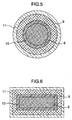
- a first superconductor 8 and a second superconductor 9 are combined so as to obtain a transversal cross sectional structure shown in Figs. 5 to 8.
- the MgB 2 superconductor is used for the first superconductor 8 and the NbTi superconductor is used for the second superconductor 9, however, the present effect can be obtained also in the other superconductors.
- a stainless steel 10 is arranged in an interface between the MgB 2 superconductor 8 and the NbTi superconductor 9, and the copper is used for an outermost layer 11.
- the MgB 2 superconductor 8 and the NbTi superconductor 9 are inverse.
- a metal superconducting material of an Nb 3 Sn group, an (NbTi) 3 Sn group, Nb 3 Al group, an Nb 3 Ge group and V 3 Ga group, or an oxide superconducting material of an Y group, a Bi group, a Ti group, an Ag-Pb group and an Hg group may be arranged in the NbTi superconductor 9.
- a superconducting property of the NbTi superconductor can be mainly made good use until a certain temperature range by employing the arrangement mentioned above, and a superconducting property of the MgB 2 superconductor having the higher critical temperature can be made good use over the certain temperature range.
- an effective superconducting property can be obtained by combining two or more kinds of superconductors not only in the temperature but also an applied magnetic field, an applied angle or the like.
- Fig. 6 shows approximately the same cross section as that in Fig. 5, however, is different in a flat cross sectional tape shape.
- this shape is most effective. This is because a high density of the superconductor can be achieved by forming in the tape shape. It is further easy to apply to various applications by constructing the superconducting wire having the structure mentioned above.
- Fig. 7 is a transversal cross sectional view of a combined superconducting wire having a multi-core structure. That is, the MgB 2 superconductor 8 is arranged as a multi-core wire rod in the stainless steel 10. It is easy to twist the wire rod by making the structure as mentioned above, and there is obtained an advantage that an AC loss can be reduced.
- Fig. 8 is a transversal cross sectional view of a combined superconducting wire having a flat-shaped multi-core structure.
- Fig. 9 has a cross sectional structure shown in Fig. 6.
- the critical current property is improved particularly below 8 K.
- the critical current property is also improved below 15 K.
- Figs. 10 and 11 are schematic cross sectional views showing a connecting method between the combined superconducting wires in accordance with the present invention.
- the superconducting wires can be connected in a superconducting state by abutting the leading end portions of the single superconducting wires or the combined superconducting wire 15 produced in the manner mentioned above with each other, or overlapping the wires with each other, applying or coating the MgB 2 powder at 0.05 to 5 g to the surface thereof, and bonding under a pressure of about 1 ton/cm 2 .
- a more effective connection can be achieved by arranging a hard block-like metal 17 such as a stainless steel, an Ni, an Ni base alloy or the like in a portion to be pressurized.
- a hard block-like metal 17 such as a stainless steel, an Ni, an Ni base alloy or the like in a portion to be pressurized.
- a resistance 10 -10 ⁇ has conventionally existed, however, the resistance value is lowered to 10-14 ⁇ by using the combined superconducting wire 15 bonded in accordance with the connecting method on the basis of the present embodiment.
- the junction may be applied to the single wire rod of each of the MgB 2 wire rod, the conventional metal group superconducting wire rod or the oxide superconducting wire rod, and it is confirmed that the present invention is a technique which can be applied to every types of wire rods.
- the resin may employ a silicon group, an urethane group or the like, and can be selected in correspondence to the purpose.
- the wire rod in accordance with the present invention can be applied widely to the superconducting devices, and an excellent effect that a high efficiency of the device can be achieved by applying the wire rod in accordance with the present invention, for example, to a large size magnet, a nuclear magnetic resonance analyzing apparatus, a medical magnetic resonance diagnosing apparatus, a superconducting electric power storage apparatus, a magnetic separating apparatus, a magnetic single crystal pulling apparatus, a refrigerator cooling superconducting magnet apparatus, and the like.
- the superconducting wire rod and the superconducting magnet can be driven by being cooled by a liquid hydrogen, a liquid neon, a refrigerator conducting cooling or the like in addition to the liquid helium, and it is possible to obtain the superconducting wire rod having the high superconducting critical current density even in the magnetic field.
Landscapes
- Engineering & Computer Science (AREA)
- Manufacturing & Machinery (AREA)
- Superconductors And Manufacturing Methods Therefor (AREA)
Abstract
Description
Further, it is desirable that the average diameter of the crystal grains is equal to or less than 20 µm. This is because the additional metal is a non-superconducting layer and an electric current pass is shut off in the case that it is larger than the grain diameter of the superconducting layer.

| Density of superconducting material (%) | 50 | 65 | 75 | 85 | 90 | 93 | 97 | 99 |
| Critical current density (x 104 A/cm2) | 0.5 | 1.1 | 2.9 | 4.1 | 24.0 | 24.4 | 24.7 | 24.7 |
| Area of defect portion (mm2) | 0 | 2 | 5 | 8 | 10 | 12.5 | 15 | 20 |
| Critical current density (x 104 A/cm2) | 22 | 20 | 19 | 19 | 6 | 6 | 2 | 1 |
Claims (7)
- A superconducting wire rod filled with or interiorly including a superconductor containing boron, wherein a metal powder is added to a super-conducting material (3) included in said superconducting wire rod (1), said metal powder is selected from at least one of indium, tin, lead, iron, magnesium and aluminum, said metal powder having an average grain diameter equal to or less than 20 µm is 5 to 25 vol% dispersed in said superconducting material, a density of the superconducting material included in the superconducting wire rod after a final work is equal to or more than 90% a theoretical density, and a critical current density is equal to or more than 1000 A/cm2.
- A superconducting wire rod as claimed in claim 1, wherein a defect portion having an area equal to or more than 10 mm2 does not exist over an entire length of the wire rod, on a surface of said superconducting wire rod.
- A superconducting wire rod as claimed in claim 1, wherein in the case that a bending strain rate capable of maintaining a critical current density Jc(l) of 90% or more of a critical current density Jc(0) at a time when no bending is applied to the wire rod is defined as an allowable bending strain rate, the allowable bending strain rate ε (%) (ε = (t/2r) x 100) is equal to or more than 0.8%, on the assumption that an entire thickness of said superconducting wire rod is set to t, a radius of bending is set to r, and a rate of bending strain is set to ε.
- A superconducting wire rod as claimed in claim 1, wherein said superconductor containing the boron is made of a complex compound with a different kind of superconductor.
- A superconducting wire rod as claimed in claim 4, wherein said different kind of superconductor is niobium titanium.
- A superconducting wire rod as claimed in claim 1, wherein a connection between superconducting wire rods mentioned above is achieved by using a connecting method corresponding to a bonding via the superconductor containing the boron.
- A method of producing a superconducting wire rod comprising:wherein a density of a superconducting material contained in the superconducting wire rod after a final process is equal to or more than 90%, and a critical current density is equal to or more than 1000 A/cm2.a step of mixing a metal powder having an average grain diameter equal to or less than 20 µm and selected from at least one of indium, tin, lead, iron, magnesium and aluminum of 5 to 25 vol% to a superconducting powder containing boron so as to produce a mixed powder;a step of charging said mixed powder to a metal pipe; anda step of wiring and/or rolling said metal pipe,
Applications Claiming Priority (2)
| Application Number | Priority Date | Filing Date | Title |
|---|---|---|---|
| JP2002358972A JP4010404B2 (en) | 2002-12-11 | 2002-12-11 | Superconducting wire and its manufacturing method |
| JP2002358972 | 2002-12-11 |
Publications (2)
| Publication Number | Publication Date |
|---|---|
| EP1429399A2 true EP1429399A2 (en) | 2004-06-16 |
| EP1429399A3 EP1429399A3 (en) | 2006-03-08 |
Family
ID=32322097
Family Applications (1)
| Application Number | Title | Priority Date | Filing Date |
|---|---|---|---|
| EP03018935A Withdrawn EP1429399A3 (en) | 2002-12-11 | 2003-08-20 | Superconducting wire rod and method of producing the same |
Country Status (3)
| Country | Link |
|---|---|
| US (1) | US20040121915A1 (en) |
| EP (1) | EP1429399A3 (en) |
| JP (1) | JP4010404B2 (en) |
Cited By (1)
| Publication number | Priority date | Publication date | Assignee | Title |
|---|---|---|---|---|
| EP2264799A1 (en) * | 2009-06-18 | 2010-12-22 | Edison S.p.A. | Superconductive element and relative preparation process |
Families Citing this family (16)
| Publication number | Priority date | Publication date | Assignee | Title |
|---|---|---|---|---|
| JP4481584B2 (en) * | 2003-04-11 | 2010-06-16 | 株式会社日立製作所 | Composite sheath MgB2 superconducting wire and method for manufacturing the same |
| JP2007221013A (en) * | 2006-02-20 | 2007-08-30 | Hitachi Ltd | Permanent current switch |
| JP5046990B2 (en) * | 2007-02-21 | 2012-10-10 | 独立行政法人物質・材料研究機構 | Manufacturing method of MgB2 superconductor and MgB2 superconductor |
| US20080236869A1 (en) * | 2007-03-30 | 2008-10-02 | General Electric Company | Low resistivity joints for joining wires and methods for making the same |
| US8244323B2 (en) * | 2008-05-27 | 2012-08-14 | Chubu University Educational Foundation | Superconducting tape wire material and method of manufacturing same |
| KR101212111B1 (en) * | 2010-06-10 | 2012-12-13 | 한국기계연구원 | Method for manufacturing magnesium diboron superconducting wire and magnesium diboron superconducting wire produced thereby |
| JP2013122981A (en) * | 2011-12-12 | 2013-06-20 | Hitachi Ltd | Superconducting magnet and method for connecting superconducting wire rod |
| GB2504670A (en) * | 2012-08-01 | 2014-02-12 | Siemens Plc | Niobium alloy superconductor manufacture using a single crystal precursor material |
| CN109155174A (en) * | 2016-03-30 | 2019-01-04 | 先锋磁体实验室有限公司 | Method of making permanent magnets |
| CN110277187A (en) * | 2018-03-13 | 2019-09-24 | 于勇 | Conductor powder conducting wire |
| JP6743233B1 (en) * | 2019-03-28 | 2020-08-19 | 株式会社フジクラ | Oxide superconducting wire |
| CN111554505B (en) * | 2020-05-26 | 2022-12-20 | 合肥夸夫超导科技有限公司 | Preparation method of PbMo6S8 superconducting wire |
| CN112415302B (en) * | 2020-10-27 | 2022-01-18 | 西安电子科技大学 | Operation and test device and method for conduction cooling high-temperature superconducting cable |
| CN114822977A (en) * | 2022-05-18 | 2022-07-29 | 华北电力大学 | Low-alternating-current-loss high-temperature superconducting conductor based on multi-filamentation treatment |
| US12221383B1 (en) * | 2024-08-02 | 2025-02-11 | Pow-Stor Inc. | Electrically conductive boron-containing material with heat and impact resistance |
| CN120183804B (en) * | 2025-05-21 | 2025-08-26 | 西安聚能超导线材科技有限公司 | Preparation method of niobium-three-tin composite wire for extremely high magnetic field and composite wire |
Family Cites Families (12)
| Publication number | Priority date | Publication date | Assignee | Title |
|---|---|---|---|---|
| US6586370B1 (en) * | 1997-02-26 | 2003-07-01 | Nove' Technologies, Inc. | Metal boride based superconducting composite |
| JP3575004B2 (en) * | 2001-01-09 | 2004-10-06 | 独立行政法人 科学技術振興機構 | Intermetallic compound superconductor composed of magnesium and boron, alloy superconductor containing the intermetallic compound, and methods of producing these |
| US20040116301A1 (en) * | 2001-02-28 | 2004-06-17 | Jeffery Tallon | Superconducting borides and wires made thereof |
| ATE318010T1 (en) * | 2001-03-05 | 2006-03-15 | Eidgenoess Tech Hochschule | METHOD FOR PRODUCING A SUPERCONDUCTING MATERIAL FROM MGB2 |
| US6687975B2 (en) * | 2001-03-09 | 2004-02-10 | Hyper Tech Research Inc. | Method for manufacturing MgB2 intermetallic superconductor wires |
| AU2002252961A1 (en) * | 2001-03-12 | 2002-09-24 | Leibniz-Institut Fur Festkorper- Und Werkstoffforschung Dresden E.V. | Mgb2 based powder for the production of super conductors, method for the use and production thereof |
| WO2002103370A2 (en) * | 2001-06-01 | 2002-12-27 | Northwestern University | Superconducting mg-mgb2 and related metal composites and methods of preparation |
| JP4055375B2 (en) * | 2001-06-15 | 2008-03-05 | 株式会社日立製作所 | Superconducting wire, manufacturing method thereof and superconducting magnet using the same |
| US20030036482A1 (en) * | 2001-07-05 | 2003-02-20 | American Superconductor Corporation | Processing of magnesium-boride superconductors |
| JP4058920B2 (en) * | 2001-07-10 | 2008-03-12 | 株式会社日立製作所 | Superconducting connection structure |
| US6946428B2 (en) * | 2002-05-10 | 2005-09-20 | Christopher M. Rey | Magnesium -boride superconducting wires fabricated using thin high temperature fibers |
| US7226894B2 (en) * | 2003-10-22 | 2007-06-05 | General Electric Company | Superconducting wire, method of manufacture thereof and the articles derived therefrom |
-
2002
- 2002-12-11 JP JP2002358972A patent/JP4010404B2/en not_active Expired - Fee Related
-
2003
- 2003-08-19 US US10/642,643 patent/US20040121915A1/en not_active Abandoned
- 2003-08-20 EP EP03018935A patent/EP1429399A3/en not_active Withdrawn
Cited By (3)
| Publication number | Priority date | Publication date | Assignee | Title |
|---|---|---|---|---|
| EP2264799A1 (en) * | 2009-06-18 | 2010-12-22 | Edison S.p.A. | Superconductive element and relative preparation process |
| US8615867B2 (en) | 2009-06-18 | 2013-12-31 | Edison S.P.A. | Superconductive element and relative preparation process |
| AU2010202501B2 (en) * | 2009-06-18 | 2014-06-26 | Edison S.P.A. | Superconductive element and relative preparation process |
Also Published As
| Publication number | Publication date |
|---|---|
| US20040121915A1 (en) | 2004-06-24 |
| EP1429399A3 (en) | 2006-03-08 |
| JP2004192934A (en) | 2004-07-08 |
| JP4010404B2 (en) | 2007-11-21 |
Similar Documents
| Publication | Publication Date | Title |
|---|---|---|
| JP4481584B2 (en) | Composite sheath MgB2 superconducting wire and method for manufacturing the same | |
| US7138581B2 (en) | Low resistance conductor, processes of production thereof, and electrical members using same | |
| EP1429399A2 (en) | Superconducting wire rod and method of producing the same | |
| EP0627773B1 (en) | Oxide superconducting wire and superconducting apparatus therewith | |
| JP4055375B2 (en) | Superconducting wire, manufacturing method thereof and superconducting magnet using the same | |
| WO2003005460A2 (en) | Processing of magnesium-boride superconductor wires | |
| US20030036482A1 (en) | Processing of magnesium-boride superconductors | |
| JP3386942B2 (en) | Oxide superconducting coil and manufacturing method thereof | |
| JP2636049B2 (en) | Method for producing oxide superconductor and method for producing oxide superconducting wire | |
| JP2009134969A (en) | Manufacturing method of MgB2 superconducting wire | |
| JP4500901B2 (en) | Composite sheathed magnesium diboride superconducting wire and its manufacturing method | |
| Yau et al. | Strain tolerance of multifilament Bi‐Pb‐Sr‐Ca‐Cu‐O/silver composite superconducting tapes | |
| US20120083415A1 (en) | Process of superconducting wire and superconducting wire | |
| Schlachter et al. | Properties of MgB2 superconductors with regard to space applications | |
| JP4456016B2 (en) | Metal sheath magnesium diboride superconducting wire and method for manufacturing the same | |
| Peter | Superconductor: Wires and cables: Materials and processes | |
| JP2003092032A (en) | Superconducting wire and method of manufacturing the same | |
| Slimani et al. | Fabrication technologies of superconducting cables and wires | |
| Fischer et al. | Fabrication of Bi-2223 tapes | |
| EP0644601A2 (en) | Oxide superconductor and method of fabricating the same | |
| KR100392511B1 (en) | Fabrication method of MgB2 superconducting wire | |
| Masur et al. | Advances in the Processing and Properties of YBa2Cu4O8 | |
| Sato | PROCESSING FOR HIGH-/C Bi-Sr-Ca-Cu-O WIRES | |
| EP0698930A1 (en) | Oxide superconductor and fabrication method of the same | |
| Balachandran et al. | Advances in processing and characterizing Bi-based superconductors |
Legal Events
| Date | Code | Title | Description |
|---|---|---|---|
| PUAI | Public reference made under article 153(3) epc to a published international application that has entered the european phase |
Free format text: ORIGINAL CODE: 0009012 |
|
| AK | Designated contracting states |
Kind code of ref document: A2 Designated state(s): AT BE BG CH CY CZ DE DK EE ES FI FR GB GR HU IE IT LI LU MC NL PT RO SE SI SK TR |
|
| AX | Request for extension of the european patent |
Extension state: AL LT LV MK |
|
| PUAL | Search report despatched |
Free format text: ORIGINAL CODE: 0009013 |
|
| AK | Designated contracting states |
Kind code of ref document: A3 Designated state(s): AT BE BG CH CY CZ DE DK EE ES FI FR GB GR HU IE IT LI LU MC NL PT RO SE SI SK TR |
|
| AX | Request for extension of the european patent |
Extension state: AL LT LV MK |
|
| 17P | Request for examination filed |
Effective date: 20060331 |
|
| AKX | Designation fees paid |
Designated state(s): DE GB IT |
|
| 17Q | First examination report despatched |
Effective date: 20060508 |
|
| GRAP | Despatch of communication of intention to grant a patent |
Free format text: ORIGINAL CODE: EPIDOSNIGR1 |
|
| RIN1 | Information on inventor provided before grant (corrected) |
Inventor name: TOKANO, KAZUMASA,C/O IND. ADM. INST. NAT. Inventor name: KITAGUCHI, HITOSHI,C/O IND. ADM. INST. NAT. Inventor name: KUMAKURA, HIROAKI,C/O IND. ADM. INST. NAT. Inventor name: OKADA, MICHIYA,C/O HITACHI, LTD. Inventor name: TANAKA, KAZUHIDE,C/O HITACHI, LTD. |
|
| STAA | Information on the status of an ep patent application or granted ep patent |
Free format text: STATUS: THE APPLICATION IS DEEMED TO BE WITHDRAWN |
|
| 18D | Application deemed to be withdrawn |
Effective date: 20080205 |