EP1429280A2 - Apparatus and methods for converting raster illustrated parts images into intelligent vector-layered files - Google Patents
Apparatus and methods for converting raster illustrated parts images into intelligent vector-layered files Download PDFInfo
- Publication number
- EP1429280A2 EP1429280A2 EP03078749A EP03078749A EP1429280A2 EP 1429280 A2 EP1429280 A2 EP 1429280A2 EP 03078749 A EP03078749 A EP 03078749A EP 03078749 A EP03078749 A EP 03078749A EP 1429280 A2 EP1429280 A2 EP 1429280A2
- Authority
- EP
- European Patent Office
- Prior art keywords
- file
- illustrated parts
- vector
- recognized
- detail
- Prior art date
- Legal status (The legal status is an assumption and is not a legal conclusion. Google has not performed a legal analysis and makes no representation as to the accuracy of the status listed.)
- Granted
Links
Images




Classifications
-
- G—PHYSICS
- G06—COMPUTING OR CALCULATING; COUNTING
- G06T—IMAGE DATA PROCESSING OR GENERATION, IN GENERAL
- G06T1/00—General purpose image data processing
-
- G—PHYSICS
- G06—COMPUTING OR CALCULATING; COUNTING
- G06T—IMAGE DATA PROCESSING OR GENERATION, IN GENERAL
- G06T19/00—Manipulating three-dimensional [3D] models or images for computer graphics
-
- G—PHYSICS
- G06—COMPUTING OR CALCULATING; COUNTING
- G06T—IMAGE DATA PROCESSING OR GENERATION, IN GENERAL
- G06T17/00—Three-dimensional [3D] modelling for computer graphics
-
- G—PHYSICS
- G06—COMPUTING OR CALCULATING; COUNTING
- G06T—IMAGE DATA PROCESSING OR GENERATION, IN GENERAL
- G06T17/00—Three-dimensional [3D] modelling for computer graphics
- G06T17/005—Tree description, e.g. octree, quadtree
-
- G—PHYSICS
- G06—COMPUTING OR CALCULATING; COUNTING
- G06V—IMAGE OR VIDEO RECOGNITION OR UNDERSTANDING
- G06V30/00—Character recognition; Recognising digital ink; Document-oriented image-based pattern recognition
- G06V30/40—Document-oriented image-based pattern recognition
- G06V30/42—Document-oriented image-based pattern recognition based on the type of document
- G06V30/422—Technical drawings; Geographical maps
-
- G—PHYSICS
- G06—COMPUTING OR CALCULATING; COUNTING
- G06T—IMAGE DATA PROCESSING OR GENERATION, IN GENERAL
- G06T2210/00—Indexing scheme for image generation or computer graphics
- G06T2210/32—Image data format
Definitions
- the present invention relates to raster illustrated part images, and more particularly to apparatus and methods for converting raster illustrated parts images into intelligent vector-layered files.
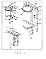
- Illustrated parts drawings identify a hierarchy of details or assemblies and parts in a manner showing how the details and parts fit together. Illustrated parts drawings may show multiple details such as the exemplary illustrated parts drawing shown in Figure 1 that includes three details labeled G, H and I. Typically, the details include references or items numbers that are indexes into a parts list where additional information about the assemblies and parts is available. A single illustrated parts drawing can include many details with dozens of item numbers.
- a task list specifies construction or maintenance steps, where each step references one or more the p ts on the illustrated parts drawing.
- a user typically ust search the drawing for the parts referenced in the step to view th part and how it relates to other parts.
- searching for the part can be time-consuming and prone to errors, especially as the number of parts contained in the illustrated parts drawing increases.
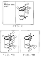
- FIG. 2 shows an illustrated parts image being used with an exemplary task list.
- the illustrated parts image identifies only the parts or items relevant to or mentioned in the current task list step (i.e., "Remove bolts, washers, and nuts").
- an illustrated parts image may be provided with an item number that is disposed at the end of a reference line (e.g., lead line, leader line, arrow, bulleted line, etc.) and that is associated with a link or index to database information about the particular component or part referenced by the item number. Accordingly, a user-click on an item number queries a database and thus allows the user to access database information associated with the item number.
- a locator e.g., lead line, leader line, arrow, bulleted line, etc.
- a locator is also disposed at the end of a reference line.
- a locator is associated with zooming functionality that allows a user to zoom in on a particular portion (e.g., component, part, detail, assembly, etc.) of the illustrated parts drawing with a user-click on the locator. Accordingly, both item numbers and locators allow a user to access additional information by way of a user-click thereon.
- the inventors have recognized a need in the art for devices and methods that improve the usability and functionality of raster illustrated parts images by converting existing raster illustrated parts images into intelligent vector-layered files in a highly accurate, efficient, and automated batch process that requires little to no user intervention.
- the present invention is directed to a system and method for converting raster illustrated parts images into intelligent vector-layered files.
- the method generally involves recognizing and removing reference labels from the raster illustrated parts image to produce a reference label scrubbed file. Reference lines are recognized and removed from the reference label scrubbed file to produce a scrubbed file, which includes a reusable base graphic.
- the scrubbed file is converted to a vector file in which the reusable base graphic is embedded as a bitmap.
- One or more vector layers are added to the vector file to produce an intelligent vector-layered file. Each vector layer includes vector elements corresponding to one of the recognized reference labels and its one or more reference lines.
- each intelligent vector-layered file 13 includes a reusable base graphic and a vector layer for each item number and locator.
- Each vector layer also includes the reference line(s) associated with the corresponding item number or locator.
- reference label shall be construed to include both item numbers and locators.
- reference line shall be construed to include any of a wide range of lines regardless of whether the line has an end designator, including but not limited to arrows, lead lines, leader lines, bulleted lines (i.e., lines with bullets as end designators), among others.
- the vector layers are preferably encoded in a file format that is compatible with existing electronic or drawing management systems to allow authors to link vector layers to related steps of a task list.
- the vector layers can be activated (i.e., made visible) or deactivated (i.e., made invisible) so that the items relevant to the current step are identified on the reusable base graphic. See Figures 4A and 4B.
- the reusable base graphic and various vector layers comprise an intelligent graphic, the display of which varies depending upon the content or particular step for which the graphics are being displayed.
- the system 10 includes a suitable processing element 12 for performing the various operations required by the present invention.
- the processing element 12 is typically comprised of a combination of hardware (e.g., one or more microprocessors, other processing devices) and software that is stored by memory and executed by the hardware.
- the processor 12 executes a detail art grouping and separation module 14, a text recognition and erasure module 16, a line recognition and erasure module 18, a graphic normalizer module 20, a vector file conversion module 22, and a vector layer builder and inserter module 24.
- the processing element 12 can be comprised of other combinations of hardware, software, firmware or the like so long as the resulting combination is capable of implementing the various operations required for converting raster illustrated images into one or more intelligent vector-layered files.
- the system 10 also includes memory which may take the form of any suitable computer readable storage device.
- the memory may comprise read only memory (ROM), random access memory (RAM), video memory (VRAM), hard disk, floppy diskette, compact disc (CD), an optical disk, magnetic tape, a combination thereof, etc.
- the memory may comprise computer readable media for storing such items as program code, software packages, programs, algorithms, information, data, files, databases, applications, among other things.
- the system 10 includes the detail art grouping and separation module 14, the text recognition and erasure module 16, the line recognition and erasure module 18, the graphic normalizer module 20, the vector file conversion module 22, and the vector layer builder and inserter module 24.
- the plurality of modules 14 through 24 may be embodied in computer-readable program code stored in one or more computer-readable storage media operatively associated with the system 10.
- the computer readable program code described herein can be conventionally programmed using any of a wide range of suitable computer readable programming languages that are now known in the art or that may be developed in the future. It is also to be understood that the computer readable program code described herein can include one or more functions, routines, subfunctions, and subroutines, and need not be combined in a single package but may instead be embodied in separate components.
- the computer readable program code may be a stand-alone application, or may be a plug-in module for an existing application and/or operating system. Alternatively, the computer readable program code may be integrated into an application or operating system.
- the computer readable program code may reside at one or more network devices (not shown), such as an administrator terminal, a server, etc.
- the system 10 further includes data and information specific to the set of raster illustrated parts images being converted. As shown, the system 10 includes a plurality of specially built textual character sets 25, 26, and 27, one set for the item numbers, one set for the detail labels, and one set for the locator labels. As explained in greater detail below, the character sets 25, 26, and 27 are used by the processing element 12 during detail art grouping and separation and during text recognition.
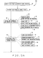
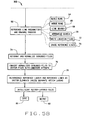
- FIG. 5A and 5B A preferred method 30 implemented by the system 10 of the present invention is illustrated in simplified flow chart form in Figures 5A and 5B.
- Figure 6 is a process flow diagram showing various files used and/or created during the method 30.
- step 32 of method 30 comprises inputting one or more files 132 ( Figure 6) from the illustrated parts document 11 into the system 10.
- the files 132 input at step 32 may comprise uncompressed TIFF (tagged image file format) files having various resolutions (e.g., 300 dpi (dots per inch) to 700 dpi) and various color depths (e.g., color depth of 8 or 256 colors, etc.).
- the system 10 executes the graphic normalizer module 20 ( Figure 3) to reformat and standardize each input file 132 ( Figure 6) to the same resolution, color depth, and compression.
- the files 134 ( Figure 6) normalized by the system 10 at step 34 may be compressed and converted to 300 dpi and 1 bit color (monochrome).
- Step 36 comprises a detail art grouping and separation process during which the system 10 executes the module 14 ( Figure 3) to separate the details within the normalized files 134 ( Figure 6) into individual or detail separated files 136.
- step 38 involves the system 10 accessing the character sets 25, 26, and 27 and using optical character recognition (ocr) to recognize the text (e.g., detail labels, locator labels, item numbers, etc.) within the raster illustrated parts images contained within the normalized files 134.
- the system 10 may, for example, execute optical character recognition (OCR) software, such as Cartouche® OCR computer software from RAF Technology, Inc. of Redmond, Washington.
- OCR optical character recognition
- the system 10 stores the recognized text and its corresponding locations.
- the recognized text is removed or erased from the raster images within the normalized files 134.
- the system 10 detects and parses the individual details within the raster images of the normalized files 134 by using geometric proximity-based calculations in conjunction with the detail labels recognized at step 38.
- the system 10 uses the detail labels as starting points to identify pixels that are connected or grouped together.
- the system 10 preferably begins searching above the detail labels for the pixels to be grouped for each detail label.
- Each collection of grouped pixels may include the artwork forming the corresponding detail and its associated reference lines.
- the system 10 preferably separates ambiguous images (i.e., images that cannot be separated out with high confidence), the system 10 also preferably flags the ambiguous images to notify a user (e.g., illustrator, etc.) of the ambiguity.
- the system 10 stores each detail found at step 44 in its own file 136 ( Figure 6). For example, the three details labeled G, H and I in Figure 1 would each be written to their own files at step 46 as illustrated in Figures 8A, 8B and 8C.
- the system 10 executes an assignment algorithm to assign and write the text recognized at step 38 to the appropriate detail file 136.
- Text assignment is preferably based upon geometric proximity reasoning (i.e., how close a particular text element is to a detail).
- the unambiguous text is preferably assigned before ambiguous text (i.e., those that cannot be assigned to a detail with high confidence).
- Each text element is preferably assigned to the detail to which its corresponding reference line is pointing.
- Step 50 comprises a reference label recognition and erasure process during which the system 10 executes the module 16 and optical character recognition computer software.
- the input for the reference label recognition and erasure process 50 comprises the detail separated files 136.
- the system 10 finds the text corresponding to the reference labels while allowing for at least some deviation in the characters.
- a "binary large object” is a grouping of all visible pixels that are connected, either horizontally, vertically or diagonally, to one or more other visible pixels in the grouping.
- a visible pixel is a pixel whose color is different than that of the background color of the image.
- step 54 comprises character recognition during which the system 10 runs a character recognition engine on the remaining "small" blobs (i.e., those binary large objects or blobs that are not too large to be characters).
- the system 10 accesses the data within the character sets 25, 26, and 27 to locate the characters within the detail separated files 136.
- the system 10 uses the output from the character recognition step 54 to find reference labels, classifying them as item numbers, locator labels or detail labels.
- Figure 9 shows the reference labels that were found in Figure 8A by the system 10.
- each recognized reference label and its respective placement or position on the image is captured or stored in an intermediate version of the raster file.
- the pixels representing each reference label are then erased or scrubbed from the images at step 60 to produce reference label scrubbed raster files 160 ( Figure 6).
- step 62 comprises a line recognition and erasure process during which the system 10 executes module 18 to identify, store, and erase the reference lines associated with the reference labels.
- the input for the line recognition and erasure process 62 comprises the reference label scrubbed raster files 160 ( Figure 6).
- a "pixel run” is a grouping of pixels that are adjacent horizontally and share the same y-coordinate, as shown in Figure 10.
- the initial runs built at step 64 each have a height of one (1) pixel but may have varying lengths or widths depending on how many adjacent pixels are found.
- a typical raster image may include tens of thousands of pixel runs.
- Figure 11A shows fifteen (15) pixel runs, each having a width or length of three (3) pixels and height of one (1) pixel, that can be merged to form the single pixel run of width three (3) pixels and height of fifteen (15) pixels shown in Figure 11B. Accordingly, horizontal lines are merged runs whose widths exceed their heights while meeting a minimum length requirement, whereas vertical lines are merged runs whose heights exceed their widths while meeting a minimum length requirement. Oblique lines are made of pixel runs that are "staircased", as shown in Figure 12.
- the system 10 searches for starting positions for reference lines by searching for pixels in the immediate proximity to where reference labels were recognized at step 50. That is, a line start is located by finding a pixel run in the immediate proximity to where a reference label was located. Once found, the pixel run is used as a starting point or seed by the system 10 to locate adjacent pixel runs that also proceed in the substantially same direction and along a substantially constant slope as the starting pixel run. When the system 10 cannot locate anymore of such adjacent pixel runs, a determination is made as to whether the collection of pixel runs, now forming a line, is sufficiently long enough for consideration as a reference line. If not, the system 10 selects another pixel run for use as starting point or seed and builds collection of pixel runs therefrom in the manner just described.
- the resolution for the raster illustrated parts images being converted may vary depending on the particular application in which the present invention is being used. Accordingly, the determination of when a collection of pixel runs is long enough for consideration as a reference line will also vary depending on the particular application in which the present invention is being used. By way of example only, a reference line might be required to be at least five to ten percent (5-10%) coverage of the artwork.
- the system 10 does not consider the line to be a reference line.
- the system 10 does, however, continue testing other lines for arrowheads.
- the system 10 can also be configured to search for other types of lines, such as lines with bullets instead of arrows, lead lines (i.e., lines without end designators), etc.
- the system 10 writes one or more location files 172 ( Figure 6) that contain data and information about the text strings for reference labels as well as their respective image locations.
- the location files 172 also contain data and information pertaining to the start and end locations of each reference line.
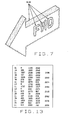
- Figure 13 there is shown an exemplary location file wherein "IN” refers to Item Number, "LO” refers to Locator, "DL” refers to Detail and “LL” refers to Leader Line.
- the system 10 creates the scrubbed files 173 ( Figure 6) containing the reusable base graphic(s) (e.g., Figure 14) by erasing the pixels forming the reference lines, and accompanying arrowheads from the reference label scrubbed files 160.
- the system 10 looks for pixels adjacent to the reference line in order to avoid erasing pixels that are also part of or overlapping other objects on the image.
- the system 10 executes the module 20 ( Figure 3) to reformat and standardize the scrubbed files 173 ( Figure 6).
- the system 10 executes the module 22 ( Figure 3) to convert the normalized scrubbed files 174 ( Figure 6) into vector files 176 that include the reusable base graphics as embedded bitmaps.
- the system 10 may encode the vector files 176 in a file format called Computer Graphic Metafile (CGM), a widely-used technical illustration format.
- CGM Computer Graphic Metafile
- other languages and file formats may be used by the system 10 to encode the vector files 176 including, but not limited to, DWG format, document exchange format (DXF), initial graphics exchange specification (IGES) format, among others.
- the system 10 executes the module 24 ( Figure 3) to create the intelligent vector-layered files 178 ( Figure 6). That is, the system 10 reintroduces into the vector files 176 the reference labels and their associated reference lines as vector elements with each reference label being within a separate vector layer.
- a "vector layer” shall be construed to include one or more vector elements that can be dynamically rendered or hidden at run-time under program control.
- the intelligent vector-layered image ( Figure 15) appears substantially identical to the original raster image shown in Figure 8A when all layers of the intelligent vector-layered image are turned on.
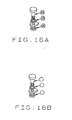
- each vector layer contains the lines emanating from the reference label, a polygon for the arrowhead at the end of each line, and a circle (for item numbers) or rectangle (for locator and detail labels) at the location of the reference label.
- Appropriate vector elements may be used to encapsulate the circle or rectangle so that it becomes a hotspot upon which a user can click to access the corresponding part information or detail.
- the text strings for the reference labels in the corresponding vector layers are located in substantially identical positions as they were in the original raster illustrated parts image 11.
- the intelligent vector-layered files 178 may be saved on a suitable computer readable medium at step 80 ( Figure 5B). Alternatively, or additionally, the intelligent vector-layered files 178 may be output at step 82, for example, to a graphical display.
- the reference labels and their reference lines may also be encoded in extensible markup language (XML).
- XML extensible markup language
- the intelligent vector-layered files 178 preferably comprise CGM Version 4 files, which allow for the control of vector layers by existing graphic display software and allow vector layers to be made visible individually or as a group. Alternatively, however, other languages and file formats may be used for the intelligent vector-layered files.
- the intelligent vector-layered files 178 allow document authors to control what layers are visible and when.
- one raster illustrated parts image with tens or hundreds of items may be reused repeatedly while displaying only the items applicable to a particular step in the task list, as shown by comparing Figure 4A (identifying all reference labels) and Figure 4B (identifying reference labels relevant to a particular step).
- item number text may be included as an aid when document authors are working with the intelligent vector-layered images.
- Document authors might need to know what each item number refers to because item number text is typically an index into a database parts table.
- the system 10 preferably comprises a batch conversion processor and thus does not require significant human intervention or manual re-authoring of the raster images. Accordingly, the present invention provides a more practical and cost-effective solution to the task of converting raster illustrated parts images to intelligent vector-layered files than the solutions presently recognized in the art, such as manually re-authoring or converting illustrated parts drawings with commercially available tools.
- the present invention dramatically improves the usability of the data within illustrated parts drawings.
- the intelligent vector-layered files are suitable for integration with other intelligent graphics capabilities, advanced and efficient user interaction, among other functional capabilities.
- the present invention is highly accurate in recognizing reference labels and reference lines from raster images.
- the present invention provides a high quality but inexpensive approach for converting paper and raster illustrated parts drawings into intelligent vector-layered drawings.
- the present invention also eliminates, or at least reduces, the need for paper-based deliveries of illustrated parts drawings in that paper-based illustrated parts drawings can be scanned and then converted by the present invention to intelligent vector-layered drawings.
Landscapes
- Engineering & Computer Science (AREA)
- Physics & Mathematics (AREA)
- General Physics & Mathematics (AREA)
- Theoretical Computer Science (AREA)
- Computer Graphics (AREA)
- Software Systems (AREA)
- Geometry (AREA)
- Computer Vision & Pattern Recognition (AREA)
- General Engineering & Computer Science (AREA)
- Computer Hardware Design (AREA)
- Artificial Intelligence (AREA)
- Multimedia (AREA)
- Processing Or Creating Images (AREA)
- Image Analysis (AREA)
- Character Input (AREA)
- Character Discrimination (AREA)
- Image Processing (AREA)
- Television Systems (AREA)
Abstract
Description
Claims (23)
- A method for converting a raster illustrated parts image into an intelligent vector-layered file, comprising:recognizing and removing reference labels from the raster illustrated parts image to produce a reference label scrubbed file;recognizing and removing reference lines from the reference label scrubbed file to produce a scrubbed file, the scrubbed file including a reusable base graphic;converting the scrubbed file to a vector file in which the reusable base graphic is embedded; andadding one or more vector layers to the vector file to produce the intelligent vector-layered file, each vector layer including one or more vector elements corresponding to one of the recognized reference labels and to one or more recognized reference lines associated with the one of the recognized reference labels.
- The method of claim 1, further comprising separating each detail of the raster illustrated parts image into a detail separated file.
- The method of claim 1 or 2, wherein recognizing and removing reference labels from the raster illustrated parts image comprises recognizing and removing reference labels from the detailed separated file.
- The method of claim 2 or 3, wherein separating each detail of the raster illustrated parts image into a detail separated file comprises:recognizing text in the raster illustrated parts image by using optical character recognition and at least one character set associated with the raster illustrated parts image;storing the recognized text and its corresponding locations;removing the recognized text from the raster illustrated parts image;detecting and parsing each detail of the raster illustrated parts image by using geometric proximity-based calculations and recognized detail labels;storing each detected and parsed detail within a detail separated file; andassigning the recognized text to the corresponding detail file by using geometric proximity reasoning.
- The method of claim 4, wherein assigning the recognized text to the corresponding detail file comprises assigning less ambiguous recognized text before assigning more ambiguous recognized text.
- The method according to any of claims 1-5, wherein recognizing and removing reference labels from the raster illustrated parts image comprises:locating large binary large objects in the raster illustrated parts image; andignoring the large binary large objects during reference label recognition.
- The method according to any of claims 1-6, wherein recognizing and removing reference labels from the raster illustrated parts image comprises:recognizing characters in the raster illustrated parts image by accessing at least one character set;recognizing reference labels from the recognized characters;storing the recognized reference labels and their corresponding locations; andremoving the recognized reference labels from the raster illustrated parts image.
- The method according to any of claims 1-7, wherein recognizing and removing reference lines from the reference label scrubbed file comprises:building a list of pixel runs;selecting from the list of pixel runs a starting pixel run adjacent one of the recognized reference labels;creating a pixel run collection by adding to the starting pixel run each pixel run adjacent and proceeding in a substantially identical direction along a substantially identical slope as the starting pixel run; anddetermining whether the pixel run collection is long enough for consideration as a reference line.
- The method of claim 8, further comprising determining whether an arrowhead is disposed at an end of the pixel run collection.
- The method of claim 8 or 9, wherein building a list of pixel runs comprises:merging pixel runs having identical x-coordinates and adjacent y-coordinates; andremoving the pixel runs merged with another pixel run from the list of pixel runs.
- The method according to any of claims 1-10, further comprising encoding the intelligent vector-layered file for compatibility with an electronic information system.
- The method according to any of claims 1-11, further comprising linking the vector layers with one or more steps in a task list.
- The method of claim 12, further comprising for a particular step of the task list displaying the reusable base graphic and the vector layers linked to the particular step.
- A method for separating details of a raster illustrated parts image, comprising:recognizing and removing text from the raster illustrated parts image by using optical character recognition and at least one character set associated with the raster illustrated parts image;detecting and parsing the details of the raster illustrated parts image using geometric proximity-based calculations and recognized detail labels;storing each detected and parsed detail within a detail separated file; andassigning the recognized text to the corresponding detail file using geometric proximity reasoning.
- The method of claim 14, wherein assigning the recognized text comprises assigning less ambiguous recognized text before assigning more ambiguous recognized text.
- A system for converting a raster illustrated parts image into an intelligent vector-layered file, comprising:a computer executable module for recognizing and removing reference labels from the raster illustrated parts image to produce a reference label scrubbed file;a computer executable module for recognizing and removing reference lines from the reference label scrubbed file to produce a scrubbed file, the scrubbed file including a reusable base graphic;a computer executable module for converting the scrubbed file to a vector file in which the reusable base graphic is embedded; anda computer executable module for adding one or more vector layers to the vector file to produce the intelligent vector-layered file, each vector layer including one or more vector elements corresponding to one of the recognized reference labels and to one or more recognized reference lines associated with the one of the recognized reference labels.
- The system of claim 16, further comprising a computer executable module for separating each detail of the raster illustrated parts image into a detail separated file.
- The system of claim 17, wherein the computer executable module for separating each detail of the raster illustrated parts image into a detail separated file comprises:a computer executable sub-module for recognizing text in the raster illustrated parts image by using optical character recognition and at least one character set associated with the raster illustrated parts image;a computer executable sub-module for storing the recognized text and its corresponding locations;a computer executable sub-module for removing the recognized text from the raster illustrated parts image;a computer executable sub-module for detecting and parsing each detail of the raster illustrated parts image by using geometric proximity-based calculations and recognized detail labels;a computer executable sub-module for storing each detected and parsed detail within a detail separated file; anda computer executable sub-module for assigning the recognized text to the corresponding detail file by using geometric proximity reasoning.
- The system of claim 18, wherein less ambiguous recognized text is assigned before more ambiguous recognized text.
- The system according to any of claims 16-19, wherein the computer executable module for recognizing and removing reference labels from the raster illustrated parts image comprises:a computer executable sub-module for recognizing characters in the raster illustrated parts image by accessing at least one character set;a computer executable sub-module for recognizing reference labels from the recognized characters;a computer executable sub-module for storing the recognized reference labels and their corresponding locations; anda computer executable sub-module for removing the recognized reference labels from the raster illustrated parts image.
- The system according to any of claims 16-20, wherein the computer executable module for recognizing and removing reference lines from the reference label scrubbed file comprises:a computer executable sub-module for building a list of pixel runs;a computer executable sub-module for selecting from the list of pixel runs a starting pixel run adjacent one of the recognized reference labels;a computer executable sub-module for creating a pixel run collection by adding to the starting pixel run each pixel run adjacent and proceeding in a substantially identical direction along a substantially identical slope as the starting pixel run; anda computer executable sub-module for determining whether the pixel run collection is long enough for consideration as a reference line.
- The system of 21, further comprising a computer executable module for determining whether an arrowhead is disposed at an end of the pixel run collection.
- The system according to any of claims 16-22, further comprising a computer executable module for encoding the intelligent vector-layered file for compatibility with an electronic information system.
Applications Claiming Priority (2)
| Application Number | Priority Date | Filing Date | Title |
|---|---|---|---|
| US318921 | 1972-12-27 | ||
| US10/318,921 US7233698B2 (en) | 2002-12-13 | 2002-12-13 | Apparatus and methods for converting raster illustrated parts images into intelligent vector-layered files |
Publications (3)
| Publication Number | Publication Date |
|---|---|
| EP1429280A2 true EP1429280A2 (en) | 2004-06-16 |
| EP1429280A3 EP1429280A3 (en) | 2006-03-08 |
| EP1429280B1 EP1429280B1 (en) | 2010-04-21 |
Family
ID=32325985
Family Applications (1)
| Application Number | Title | Priority Date | Filing Date |
|---|---|---|---|
| EP03078749A Expired - Lifetime EP1429280B1 (en) | 2002-12-13 | 2003-11-27 | Apparatus and methods for converting raster illustrated parts images into intelligent vector-layered files |
Country Status (6)
| Country | Link |
|---|---|
| US (2) | US7233698B2 (en) |
| EP (1) | EP1429280B1 (en) |
| JP (1) | JP4274920B2 (en) |
| KR (1) | KR101015765B1 (en) |
| AT (1) | ATE465465T1 (en) |
| DE (1) | DE60332209D1 (en) |
Families Citing this family (21)
| Publication number | Priority date | Publication date | Assignee | Title |
|---|---|---|---|---|
| US7233698B2 (en) | 2002-12-13 | 2007-06-19 | The Boeing Company | Apparatus and methods for converting raster illustrated parts images into intelligent vector-layered files |
| US20060214947A1 (en) * | 2005-03-23 | 2006-09-28 | The Boeing Company | System, method, and computer program product for animating drawings |
| JP2007072528A (en) * | 2005-09-02 | 2007-03-22 | Internatl Business Mach Corp <Ibm> | Method, program and device for analyzing document structure |
| US20070162842A1 (en) * | 2006-01-09 | 2007-07-12 | Apple Computer, Inc. | Selective content imaging for web pages |
| US8381164B2 (en) * | 2006-03-28 | 2013-02-19 | The Boeing Company | Method and system of intelligent interactive graphics electrical plug map to analyze text and distances between electrical contacts and physical layout file builder |
| US8260689B2 (en) * | 2006-07-07 | 2012-09-04 | Dollens Joseph R | Method and system for managing and displaying product images |
| US10614513B2 (en) | 2006-07-07 | 2020-04-07 | Joseph R. Dollens | Method and system for managing and displaying product images with progressive resolution display |
| US12373883B2 (en) | 2006-07-07 | 2025-07-29 | Joseph R. Dollens | Method and system for managing and displaying images with progressive resolution display throughout artificial realities |
| US11049175B2 (en) | 2006-07-07 | 2021-06-29 | Joseph R. Dollens | Method and system for managing and displaying product images with progressive resolution display with audio commands and responses |
| US9691098B2 (en) | 2006-07-07 | 2017-06-27 | Joseph R. Dollens | Method and system for managing and displaying product images with cloud computing |
| US11481834B2 (en) | 2006-07-07 | 2022-10-25 | Joseph R. Dollens | Method and system for managing and displaying product images with progressive resolution display with artificial realities |
| US8554639B2 (en) * | 2006-07-07 | 2013-10-08 | Joseph R. Dollens | Method and system for managing and displaying product images |
| CN101630416A (en) * | 2008-07-17 | 2010-01-20 | 鸿富锦精密工业(深圳)有限公司 | System and method for editing pictures |
| US8339417B2 (en) * | 2008-07-25 | 2012-12-25 | Navteq B.V. | Open area maps based on vector graphics format images |
| US9223769B2 (en) | 2011-09-21 | 2015-12-29 | Roman Tsibulevskiy | Data processing systems, devices, and methods for content analysis |
| US10482512B2 (en) | 2013-05-31 | 2019-11-19 | Michele Meek | Systems and methods for facilitating the retail shopping experience online |
| US10402673B1 (en) | 2018-10-04 | 2019-09-03 | Capital One Services, Llc | Systems and methods for digitized document image data spillage recovery |
| US11074473B1 (en) | 2020-01-21 | 2021-07-27 | Capital One Services, Llc | Systems and methods for digitized document image text contouring |
| KR102828974B1 (en) | 2022-07-21 | 2025-07-04 | 주식회사 캐디안 | System and method for converting raster images of traditional wooden buildings into cad electronic drawings |
| KR102481005B1 (en) | 2022-07-27 | 2022-12-26 | 주식회사 이안 | System for creating electronic piping drawings using parer piping drawings |
| KR102732289B1 (en) | 2023-08-18 | 2024-11-20 | 주식회사 엠포컴퍼니 | Vector image generating method for generating indoor 3d drawings and generating method for indoor 3d drawings |
Family Cites Families (24)
| Publication number | Priority date | Publication date | Assignee | Title |
|---|---|---|---|---|
| JPS6381574A (en) | 1986-09-25 | 1988-04-12 | Toshiba Corp | Graphic data base input device |
| JPH07117967B2 (en) | 1987-02-20 | 1995-12-18 | 三菱電機株式会社 | Drawing processing system |
| US4884199A (en) | 1987-03-02 | 1989-11-28 | International Business Macines Corporation | User transaction guidance |
| CA2066559A1 (en) * | 1991-07-29 | 1993-01-30 | Walter S. Rosenbaum | Non-text object storage and retrieval |
| US5644656A (en) * | 1994-06-07 | 1997-07-01 | Massachusetts Institute Of Technology | Method and apparatus for automated text recognition |
| JP3209003B2 (en) * | 1994-08-04 | 2001-09-17 | 日産自動車株式会社 | Method and apparatus for automatically generating a three-dimensional shape |
| US5761328A (en) * | 1995-05-22 | 1998-06-02 | Solberg Creations, Inc. | Computer automated system and method for converting source-documents bearing alphanumeric text relating to survey measurements |
| US5963966A (en) * | 1995-11-08 | 1999-10-05 | Cybernet Systems Corporation | Automated capture of technical documents for electronic review and distribution |
| US5845288A (en) * | 1995-12-11 | 1998-12-01 | Xerox Corporation | Automated system for indexing graphical documents having associated text labels |
| US6006232A (en) * | 1997-10-21 | 1999-12-21 | At&T Corp. | System and method for multirecord compression in a relational database |
| JP2000099545A (en) | 1998-09-22 | 2000-04-07 | Akutopasu:Kk | Manufacturing method of recording medium |
| US6336124B1 (en) * | 1998-10-01 | 2002-01-01 | Bcl Computers, Inc. | Conversion data representing a document to other formats for manipulation and display |
| US6621941B1 (en) * | 1998-12-18 | 2003-09-16 | Xerox Corporation | System of indexing a two dimensional pattern in a document drawing |
| US6961897B1 (en) * | 1999-06-14 | 2005-11-01 | Lockheed Martin Corporation | System and method for interactive electronic media extraction for web page generation |
| GB2365548A (en) | 2000-02-15 | 2002-02-20 | Vhsoft Technologies Company Lt | A method for automatically indexing engineering drawings through their associated text |
| JP4189506B2 (en) * | 2000-06-09 | 2008-12-03 | コニカミノルタビジネステクノロジーズ株式会社 | Apparatus, method and recording medium for image processing |
| GB2364813B (en) | 2000-07-13 | 2004-12-29 | Vhsoft Technologies Company Lt | Computer automated process for analysing and interpreting engineering drawings |
| GB2366108A (en) | 2000-07-14 | 2002-02-27 | Vhsoft Technologies Company Lt | Vectorization of raster images |
| JP4851017B2 (en) | 2001-02-28 | 2012-01-11 | ミサワホーム株式会社 | Parts information management device |
| US6826305B2 (en) * | 2001-03-27 | 2004-11-30 | Ncr Corporation | Methods and apparatus for locating and identifying text labels in digital images |
| US7200271B2 (en) * | 2001-03-29 | 2007-04-03 | The Boeing Company | Method, computer program product, and system for performing automated text recognition and text search within a graphic file |
| US6766331B2 (en) * | 2001-03-29 | 2004-07-20 | The Boeing Company | Method, computer program product, and system for creating and viewing an intelligent graphics file including parts information |
| US7233698B2 (en) | 2002-12-13 | 2007-06-19 | The Boeing Company | Apparatus and methods for converting raster illustrated parts images into intelligent vector-layered files |
| US20040151377A1 (en) | 2003-02-04 | 2004-08-05 | Boose Molly L. | Apparatus and methods for converting network drawings from raster format to vector format |
-
2002
- 2002-12-13 US US10/318,921 patent/US7233698B2/en not_active Expired - Lifetime
-
2003
- 2003-11-27 AT AT03078749T patent/ATE465465T1/en not_active IP Right Cessation
- 2003-11-27 EP EP03078749A patent/EP1429280B1/en not_active Expired - Lifetime
- 2003-11-27 DE DE60332209T patent/DE60332209D1/en not_active Expired - Lifetime
- 2003-12-09 JP JP2003410314A patent/JP4274920B2/en not_active Expired - Fee Related
- 2003-12-12 KR KR1020030090653A patent/KR101015765B1/en not_active Expired - Fee Related
-
2006
- 2006-09-22 US US11/534,471 patent/US7561742B2/en not_active Expired - Fee Related
Also Published As
| Publication number | Publication date |
|---|---|
| KR101015765B1 (en) | 2011-02-22 |
| US7561742B2 (en) | 2009-07-14 |
| US20040114801A1 (en) | 2004-06-17 |
| JP2004199671A (en) | 2004-07-15 |
| US20070064013A1 (en) | 2007-03-22 |
| EP1429280A3 (en) | 2006-03-08 |
| DE60332209D1 (en) | 2010-06-02 |
| JP4274920B2 (en) | 2009-06-10 |
| ATE465465T1 (en) | 2010-05-15 |
| US7233698B2 (en) | 2007-06-19 |
| EP1429280B1 (en) | 2010-04-21 |
| KR20040052191A (en) | 2004-06-22 |
Similar Documents
| Publication | Publication Date | Title |
|---|---|---|
| US7233698B2 (en) | Apparatus and methods for converting raster illustrated parts images into intelligent vector-layered files | |
| US7013309B2 (en) | Method and apparatus for extracting anchorable information units from complex PDF documents | |
| US6886131B1 (en) | Data processing method and apparatus | |
| KR101769918B1 (en) | Recognition device based deep learning for extracting text from images | |
| US7305612B2 (en) | Systems and methods for automatic form segmentation for raster-based passive electronic documents | |
| US10223345B2 (en) | Interactively predicting fields in a form | |
| US9514103B2 (en) | Effective system and method for visual document comparison using localized two-dimensional visual fingerprints | |
| US5893127A (en) | Generator for document with HTML tagged table having data elements which preserve layout relationships of information in bitmap image of original document | |
| EP0702322B1 (en) | Method and apparatus for identifying words described in a portable electronic document | |
| JP3282860B2 (en) | Apparatus for processing digital images of text on documents | |
| EP1457917B1 (en) | Apparatus and methods for converting network drawings from raster format to vector format | |
| EP1107169A2 (en) | Method and apparatus for performing document structure analysis | |
| US7035463B1 (en) | Document image processor, method for extracting document title, and method for imparting document tag information | |
| US7200271B2 (en) | Method, computer program product, and system for performing automated text recognition and text search within a graphic file | |
| JPH06111056A (en) | Data processing system and method for repairing character recognition error in digital image of document format | |
| CN101292259A (en) | Method and system for image matching in a mixed media environment | |
| JP3683925B2 (en) | Electronic filing device | |
| US7746341B2 (en) | System and method for parsing point-cloud data | |
| CN117649671A (en) | Express package main distribution site sorting method, device, equipment and storage medium | |
| CN114596577B (en) | Image processing method, device, electronic device and storage medium | |
| KR20180126352A (en) | Recognition device based deep learning for extracting text from images | |
| Ondrejcek et al. | Information extraction from scanned engineering drawings | |
| JPH10162098A (en) | Document digitizing device and document digitizing method | |
| Yamashita et al. | A document recognition system and its applications | |
| JP2001034763A (en) | Document image processing apparatus, document title extracting method and document tag information providing method |
Legal Events
| Date | Code | Title | Description |
|---|---|---|---|
| PUAI | Public reference made under article 153(3) epc to a published international application that has entered the european phase |
Free format text: ORIGINAL CODE: 0009012 |
|
| AK | Designated contracting states |
Kind code of ref document: A2 Designated state(s): AT BE BG CH CY CZ DE DK EE ES FI FR GB GR HU IE IT LI LU MC NL PT RO SE SI SK TR |
|
| AX | Request for extension of the european patent |
Extension state: AL LT LV MK |
|
| PUAL | Search report despatched |
Free format text: ORIGINAL CODE: 0009013 |
|
| AK | Designated contracting states |
Kind code of ref document: A3 Designated state(s): AT BE BG CH CY CZ DE DK EE ES FI FR GB GR HU IE IT LI LU MC NL PT RO SE SI SK TR |
|
| AX | Request for extension of the european patent |
Extension state: AL LT LV MK |
|
| 17P | Request for examination filed |
Effective date: 20060727 |
|
| AKX | Designation fees paid |
Designated state(s): AT BE BG CH CY CZ DE DK EE ES FI FR GB GR HU IE IT LI LU MC NL PT RO SE SI SK TR |
|
| 17Q | First examination report despatched |
Effective date: 20061212 |
|
| RAP1 | Party data changed (applicant data changed or rights of an application transferred) |
Owner name: THE BOEING COMPANY |
|
| GRAP | Despatch of communication of intention to grant a patent |
Free format text: ORIGINAL CODE: EPIDOSNIGR1 |
|
| GRAS | Grant fee paid |
Free format text: ORIGINAL CODE: EPIDOSNIGR3 |
|
| GRAA | (expected) grant |
Free format text: ORIGINAL CODE: 0009210 |
|
| AK | Designated contracting states |
Kind code of ref document: B1 Designated state(s): AT BE BG CH CY CZ DE DK EE ES FI FR GB GR HU IE IT LI LU MC NL PT RO SE SI SK TR |
|
| REG | Reference to a national code |
Ref country code: GB Ref legal event code: FG4D |
|
| REG | Reference to a national code |
Ref country code: CH Ref legal event code: EP |
|
| REG | Reference to a national code |
Ref country code: IE Ref legal event code: FG4D |
|
| REF | Corresponds to: |
Ref document number: 60332209 Country of ref document: DE Date of ref document: 20100602 Kind code of ref document: P |
|
| REG | Reference to a national code |
Ref country code: NL Ref legal event code: VDEP Effective date: 20100421 |
|
| PG25 | Lapsed in a contracting state [announced via postgrant information from national office to epo] |
Ref country code: NL Free format text: LAPSE BECAUSE OF FAILURE TO SUBMIT A TRANSLATION OF THE DESCRIPTION OR TO PAY THE FEE WITHIN THE PRESCRIBED TIME-LIMIT Effective date: 20100421 Ref country code: ES Free format text: LAPSE BECAUSE OF FAILURE TO SUBMIT A TRANSLATION OF THE DESCRIPTION OR TO PAY THE FEE WITHIN THE PRESCRIBED TIME-LIMIT Effective date: 20100801 Ref country code: SE Free format text: LAPSE BECAUSE OF FAILURE TO SUBMIT A TRANSLATION OF THE DESCRIPTION OR TO PAY THE FEE WITHIN THE PRESCRIBED TIME-LIMIT Effective date: 20100421 |
|
| PG25 | Lapsed in a contracting state [announced via postgrant information from national office to epo] |
Ref country code: SI Free format text: LAPSE BECAUSE OF FAILURE TO SUBMIT A TRANSLATION OF THE DESCRIPTION OR TO PAY THE FEE WITHIN THE PRESCRIBED TIME-LIMIT Effective date: 20100421 Ref country code: AT Free format text: LAPSE BECAUSE OF FAILURE TO SUBMIT A TRANSLATION OF THE DESCRIPTION OR TO PAY THE FEE WITHIN THE PRESCRIBED TIME-LIMIT Effective date: 20100421 Ref country code: FI Free format text: LAPSE BECAUSE OF FAILURE TO SUBMIT A TRANSLATION OF THE DESCRIPTION OR TO PAY THE FEE WITHIN THE PRESCRIBED TIME-LIMIT Effective date: 20100421 |
|
| PG25 | Lapsed in a contracting state [announced via postgrant information from national office to epo] |
Ref country code: CY Free format text: LAPSE BECAUSE OF FAILURE TO SUBMIT A TRANSLATION OF THE DESCRIPTION OR TO PAY THE FEE WITHIN THE PRESCRIBED TIME-LIMIT Effective date: 20100421 Ref country code: GR Free format text: LAPSE BECAUSE OF FAILURE TO SUBMIT A TRANSLATION OF THE DESCRIPTION OR TO PAY THE FEE WITHIN THE PRESCRIBED TIME-LIMIT Effective date: 20100722 |
|
| PG25 | Lapsed in a contracting state [announced via postgrant information from national office to epo] |
Ref country code: EE Free format text: LAPSE BECAUSE OF FAILURE TO SUBMIT A TRANSLATION OF THE DESCRIPTION OR TO PAY THE FEE WITHIN THE PRESCRIBED TIME-LIMIT Effective date: 20100421 Ref country code: DK Free format text: LAPSE BECAUSE OF FAILURE TO SUBMIT A TRANSLATION OF THE DESCRIPTION OR TO PAY THE FEE WITHIN THE PRESCRIBED TIME-LIMIT Effective date: 20100421 Ref country code: PT Free format text: LAPSE BECAUSE OF FAILURE TO SUBMIT A TRANSLATION OF THE DESCRIPTION OR TO PAY THE FEE WITHIN THE PRESCRIBED TIME-LIMIT Effective date: 20100823 |
|
| PLBE | No opposition filed within time limit |
Free format text: ORIGINAL CODE: 0009261 |
|
| STAA | Information on the status of an ep patent application or granted ep patent |
Free format text: STATUS: NO OPPOSITION FILED WITHIN TIME LIMIT |
|
| PG25 | Lapsed in a contracting state [announced via postgrant information from national office to epo] |
Ref country code: BE Free format text: LAPSE BECAUSE OF FAILURE TO SUBMIT A TRANSLATION OF THE DESCRIPTION OR TO PAY THE FEE WITHIN THE PRESCRIBED TIME-LIMIT Effective date: 20100421 Ref country code: RO Free format text: LAPSE BECAUSE OF FAILURE TO SUBMIT A TRANSLATION OF THE DESCRIPTION OR TO PAY THE FEE WITHIN THE PRESCRIBED TIME-LIMIT Effective date: 20100421 Ref country code: SK Free format text: LAPSE BECAUSE OF FAILURE TO SUBMIT A TRANSLATION OF THE DESCRIPTION OR TO PAY THE FEE WITHIN THE PRESCRIBED TIME-LIMIT Effective date: 20100421 Ref country code: CZ Free format text: LAPSE BECAUSE OF FAILURE TO SUBMIT A TRANSLATION OF THE DESCRIPTION OR TO PAY THE FEE WITHIN THE PRESCRIBED TIME-LIMIT Effective date: 20100421 |
|
| 26N | No opposition filed |
Effective date: 20110124 |
|
| PG25 | Lapsed in a contracting state [announced via postgrant information from national office to epo] |
Ref country code: IT Free format text: LAPSE BECAUSE OF FAILURE TO SUBMIT A TRANSLATION OF THE DESCRIPTION OR TO PAY THE FEE WITHIN THE PRESCRIBED TIME-LIMIT Effective date: 20100421 |
|
| PG25 | Lapsed in a contracting state [announced via postgrant information from national office to epo] |
Ref country code: MC Free format text: LAPSE BECAUSE OF NON-PAYMENT OF DUE FEES Effective date: 20101130 |
|
| REG | Reference to a national code |
Ref country code: CH Ref legal event code: PL |
|
| PG25 | Lapsed in a contracting state [announced via postgrant information from national office to epo] |
Ref country code: CH Free format text: LAPSE BECAUSE OF NON-PAYMENT OF DUE FEES Effective date: 20101130 Ref country code: LI Free format text: LAPSE BECAUSE OF NON-PAYMENT OF DUE FEES Effective date: 20101130 |
|
| PG25 | Lapsed in a contracting state [announced via postgrant information from national office to epo] |
Ref country code: IE Free format text: LAPSE BECAUSE OF NON-PAYMENT OF DUE FEES Effective date: 20101127 |
|
| PG25 | Lapsed in a contracting state [announced via postgrant information from national office to epo] |
Ref country code: BG Free format text: LAPSE BECAUSE OF FAILURE TO SUBMIT A TRANSLATION OF THE DESCRIPTION OR TO PAY THE FEE WITHIN THE PRESCRIBED TIME-LIMIT Effective date: 20100421 Ref country code: LU Free format text: LAPSE BECAUSE OF NON-PAYMENT OF DUE FEES Effective date: 20101127 Ref country code: HU Free format text: LAPSE BECAUSE OF FAILURE TO SUBMIT A TRANSLATION OF THE DESCRIPTION OR TO PAY THE FEE WITHIN THE PRESCRIBED TIME-LIMIT Effective date: 20101022 |
|
| PG25 | Lapsed in a contracting state [announced via postgrant information from national office to epo] |
Ref country code: TR Free format text: LAPSE BECAUSE OF FAILURE TO SUBMIT A TRANSLATION OF THE DESCRIPTION OR TO PAY THE FEE WITHIN THE PRESCRIBED TIME-LIMIT Effective date: 20100421 |
|
| PG25 | Lapsed in a contracting state [announced via postgrant information from national office to epo] |
Ref country code: BG Free format text: LAPSE BECAUSE OF FAILURE TO SUBMIT A TRANSLATION OF THE DESCRIPTION OR TO PAY THE FEE WITHIN THE PRESCRIBED TIME-LIMIT Effective date: 20100721 |
|
| REG | Reference to a national code |
Ref country code: FR Ref legal event code: PLFP Year of fee payment: 13 |
|
| REG | Reference to a national code |
Ref country code: FR Ref legal event code: PLFP Year of fee payment: 14 |
|
| REG | Reference to a national code |
Ref country code: FR Ref legal event code: PLFP Year of fee payment: 15 |
|
| PGFP | Annual fee paid to national office [announced via postgrant information from national office to epo] |
Ref country code: DE Payment date: 20191127 Year of fee payment: 17 |
|
| PGFP | Annual fee paid to national office [announced via postgrant information from national office to epo] |
Ref country code: FR Payment date: 20191125 Year of fee payment: 17 |
|
| PGFP | Annual fee paid to national office [announced via postgrant information from national office to epo] |
Ref country code: GB Payment date: 20191127 Year of fee payment: 17 |
|
| REG | Reference to a national code |
Ref country code: DE Ref legal event code: R119 Ref document number: 60332209 Country of ref document: DE |
|
| GBPC | Gb: european patent ceased through non-payment of renewal fee |
Effective date: 20201127 |
|
| PG25 | Lapsed in a contracting state [announced via postgrant information from national office to epo] |
Ref country code: FR Free format text: LAPSE BECAUSE OF NON-PAYMENT OF DUE FEES Effective date: 20201130 |
|
| PG25 | Lapsed in a contracting state [announced via postgrant information from national office to epo] |
Ref country code: DE Free format text: LAPSE BECAUSE OF NON-PAYMENT OF DUE FEES Effective date: 20210601 Ref country code: GB Free format text: LAPSE BECAUSE OF NON-PAYMENT OF DUE FEES Effective date: 20201127 |