EP1429252A2 - Debug device, debug method and computer readable storage medium - Google Patents
Debug device, debug method and computer readable storage medium Download PDFInfo
- Publication number
- EP1429252A2 EP1429252A2 EP03257737A EP03257737A EP1429252A2 EP 1429252 A2 EP1429252 A2 EP 1429252A2 EP 03257737 A EP03257737 A EP 03257737A EP 03257737 A EP03257737 A EP 03257737A EP 1429252 A2 EP1429252 A2 EP 1429252A2
- Authority
- EP
- European Patent Office
- Prior art keywords
- program
- debug
- serial
- parallel
- data
- Prior art date
- Legal status (The legal status is an assumption and is not a legal conclusion. Google has not performed a legal analysis and makes no representation as to the accuracy of the status listed.)
- Withdrawn
Links
Images




Classifications
-
- G—PHYSICS
- G06—COMPUTING OR CALCULATING; COUNTING
- G06F—ELECTRIC DIGITAL DATA PROCESSING
- G06F11/00—Error detection; Error correction; Monitoring
- G06F11/36—Prevention of errors by analysis, debugging or testing of software
- G06F11/362—Debugging of software
Definitions
- the present invention relates to a debug device and a debug method for converting a parallel program to a serial program and executing debugging.
- the present invention also relates to a storage medium for storing a program that implements such debug method.
- parallel programs programs written in parallel programming languages are referred to as parallel programs.
- serial programs programs written in the programming languages for describing serial processing are referred to as serial programs.
- debugging signifies identifying and correcting bugs of a program.
- Parallel programming languages are generally used for describing the processing to execute some tasks concurrently in parallel.
- a parallel programming language is used as a programming language rather than a serial processing because the internal operation of the LSI is basically parallel.
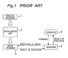
- a parallel program 1 is automatically converted to a serial program 4 by a serialization unit 2 and the obtained serial program 4 is executed on the computer. If a bug (failure) is found out in the original parallel program 1 as a result of executing the serial program 4, a designer runs the serial program 4 on a debugger 6 to specify the location of the bug, and then corrects the corresponding location in the original parallel program 1.
- an operator who performs debugging needs to proceed with the operation while obtaining the correspondence between the lines in the parallel program 1 and the lines in serial program 4 by him/herself. Further, the operator also needs to proceed with the operation while obtaining the correspondence between the variable identifiers in the parallel program and the variable identifiers in the serial program by him/herself. As a result, the operation of converting the parallel program to the serial program and executing debugging suffers considerable deterioration of efficiency and takes long time.
- a parallel program 1 is once converted to a serial program 4 for correction. Specifically, if a bug is found in the serial program 4, not the original parallel program 1 but the serial program 4 is corrected. Then, the corrected serial program is converted to a parallel program 10 by a parallelization unit 9 (see Japanese Patent Laid-Open Publication HEI 8-16429 as an example).
- An object of the present invention is therefore to provide a debug device for use in converting a parallel program to a serial program and executing debugging, which allows an operator to efficiently perform a debug operation.
- Another object of the present invention is to provide a debug method for use in converting a parallel program to a serial program and executing debugging, which enables an operator to efficiently perform a debug operation.
- Still another object of the present invention is to provide a storage medium for storing a program that implements such debug method.
- the present invention provides a debug device for use in converting a parallel program to a serial program and executing debugging, characterized by:
- the serialization means converts a parallel program to a serial program and creates debug data that indicates a corresponding relation between the parallel program and the serial program.
- the storage means stores the debug data.
- the conversion means converts the data of the parallel program and the serial program that correspond to each other based on the debug data. Therefore, an operator who performs debugging does not have to convert the data of the parallel program and the serial program that correspond to each other by him/herself. This enables the operator to perform the debug operation efficiently in a short period of time.
- an operator can perform the debug operation with a sense as if to directly debug the parallel program through the conversion means. For example, the operator can identify the location of a bug with use of a line number and a variable identifier in the original parallel program. Then, the operator can correct and eliminate the bug with use of the line number and the variable identifier in the original parallel program.
- the debug data indicates a line number correspondence between the parallel program and the serial program.
- the debug data indicates the line number correspondence between the parallel program and the serial program
- an operator who performs debugging can easily obtain the line number correspondence between the parallel program and the serial program based on the debug data. This enables the operator to perform the debug operation efficiently in a short period of time.
- the conversion means converts the line numbers of the parallel program and the serial program that correspond to each other based on the debug data
- the operator can perform the debug operation further more efficiently in a short period of time.
- the debug data indicates a variable identifier correspondence between the parallel program and the serial program.
- the debug device in this embodiment since the debug data indicates the variable identifier correspondence between the parallel program and the serial program, an operator who performs debugging can easily obtain the variable identifier correspondence between the parallel program and the serial program based on the debug data. This enables the operator to perform the debug operation efficiently in a short period of time. Particularly in the case where the conversion means converts the variable identifiers of the parallel program and the serial program that correspond to each other based on the debug data, the operator can perform the debug operation further more efficiently in a short period of time.
- the debug data indicates a line number correspondence and a variable identifier correspondence between the parallel program and the serial program
- the debug device of this embodiment since the debug data indicates the line number correspondence and the variable identifier correspondence between the parallel program and the serial program, an operator who performs debugging can easily obtain the line number correspondence and the variable identifier correspondence between the parallel program and the serial program based on the debug data. This enables the operator to perform the debug operation efficiently in a short period of time. Particularly in the case where the conversion means converts the line numbers and the variable identifiers of the parallel program and the serial program that correspond to each other based on the debug data, the operator can perform the debug operation further more efficiently in a short period of time.
- the invention also provides a debug method for converting a parallel program to a serial program and executing debugging, characterized by:
- a parallel program is converted to a serial program by the serialization means.
- the debug data indicating the corresponding relation between the parallel program and the serial program is created.
- the debug data is stored in the storage means. Based on the debug data, data of the parallel program and the serial program that correspond to each other are converted by the conversion means. Therefore, an operator who performs debugging does not have to convert the data of the parallel program and the serial program that correspond to each other by him/herself. This enables the operator to perform the debug operation efficiently in a short period of time.
- the present invention further provides a computer-readable storage medium that stores a program for implementing the above debug method.
- a program stored in the storage medium of the present invention is read by computer and executed, then the above-described debug method can be implemented. Therefore, an operator can perform the debug operation efficiently in a short period of time.
- Fig. 1 is an explanatory view showing a conventional method for converting a parallel program to a serial program and executing debugging
- Fig. 2 is an explanatory view showing a conventional method for correcting not an original parallel program but a serial program and converting the corrected serial program to a parallel program;
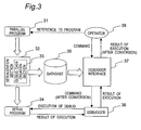
- Fig. 3 is a view showing the configuration of a debug device in one embodiment of the present invention.
- Fig. 4 is a view showing an example of the parallel program
- Fig. 5 is a view showing a serial program (former portion) obtained by converting the parallel program of Fig. 4;
- Fig. 6 is a view showing a serial program (latter portion) obtained by converting the parallel program of Fig. 4;
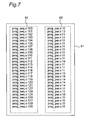
- Fig. 7 is a view showing line number corresponding data as debug data stored in a database
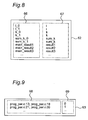
- Fig. 8 is a view illustrating variable identifier corresponding data as debug data stored in a database
- Fig. 9 is a view illustrating scope data as debug data stored in a database
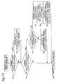
- Fig. 10 is a flow chart showing the processing for executing debugging (when a command is issued).
- Fig. 11 is a flow chart showing the processing for executing debugging (when a result is outputted).
- Fig. 3 shows a configuration of a debug device in one embodiment of the present invention.
- the debug device has a serialization section 32 as a serialization means, a database 35 as a storage means, a debugger 36 as a tool for debugging the serial program and a debugger interface 37 as a conversion means so as to convert a parallel program 31 to a serial program 34 and thereafter to execute debugging.
- the serialization section 32 executes a serialization processing to convert the parallel program 31 to the serial program 34. It is to be noted that a known method may be adopted for the serialization processing.
- a debug data creation section 33 is included inside the serialization section 32.
- the debug data creation section 33 creates debug data indicating the corresponding relation between the parallel program 31 and the serial program 34 concurrently with execution of the serialization processing.
- the debug data is stored in the database 35.
- the debugger 36 receives a command inputted by an operator through the debugger interface 37, and debugs the serial program 34 in response to the received command.
- the debugger interface 37 receives a command from a debug operator 38, and issues a command converted as needed with reference to the database 35 to the debugger 36.
- the debugger interface 37 also receives an output from the debugger 36, and outputs an output converted as needed with reference to the database 35 to the debug operator 38.
- the debug device also has a display unit that displays the program subjected to debugging, and an output unit that supplies an output of the debug operation to the operator in addition to the above-stated components.
- the parallel program 31 has the grammar of extended C language, and the processings executed in parallel are described in the range enclosed within braces ⁇ placed after a key word "par".
- the processings 41, 42 enclosed with fine dotted lines are independently executed in parallel. Since these processings 41, 42 are independent from each other, each of them may include variables of the same names such as variable i and variable k.
- variable i included in the processing 41 is given a numeral 43, while variable i included in the processing 42 is given a numeral 44.
- serialization section 32 serializes the parallel program 31 with use of C language to output a program having contents as shown in Fig. 5 to Fig. 6 as a serial program 34.
- Figs. 5 and 6 represent former and latter portions, respectively.
- the line numbers (100, 101, ..., 155) 55 shown in the left column in Figs. 5 and 6 are added for explanation, and not included in the parallel program 34.
- the processings 51, 52 enclosed with fine dotted lines correspond to the processings 41, 42 in Fig. 4 respectively, and operate serially.
- Variable i_0 (shown by numeral 53) and variable i_1 (shown by numeral 54) in the serial program 34 correspond to variable i (shown by numeral 43) in the processing 41 and variable i (shown by numeral 44) in the processing 42, respectively, in the parallel program 31.
- the variables are distinguished from each other by adding scope numbers such as "_0" and "_1" to the same variable identifiers included in the processings 41 and 42, respectively. This is because the same variable identifier is treated as indicating the same entity in the serial program (more specifically, one processing block of the serial program), where it is not allowed that the same variable identifiers having different entities exist.
- the processings 51, 52 included in the serial program 34 are executed in pseudo-parallel based on the processings other than the portion enclosed within the fine dotted lines in Fig. 5.
- the serialization section 32 converts the parallel program 31 to the serial program 34, while at the same time the debug data creation section 33 inside the serialization section 32 creates debug data indicating the corresponding relation between the parallel program 31 and the serial program 34.
- the created debug data is stored in the database 35.
- the debug data includes line number corresponding data 61 shown in Fig. 7, variable identifier corresponding data 62 shown in Fig. 8 and a scope data 63 shown in Fig. 9.
- the line number corresponding data 61 shown in Fig. 7 indicates the corresponding relation between line numbers (shown in a row in the right column) for executing a given processing in the parallel program 31 and line numbers (shown in a row in the left column) for executing the same processing in the serial program 34. It is indicated in Fig. 7 that the 15th line of a parallel program (“prog_par.c”) corresponds to the 117th line of a serial program ("prog_seq.c”), for example.
- the line number corresponding data 61 is created by the debug data creation section 33 in relationship between the line numbers of original lines in the parallel program 31 and the line numbers in the converted serial program 34 when the serialization section 32 converts the lines of the parallel program 31 to the lines of the serial program 34, and registered in the database 35.
- variable identifier corresponding data 62 shown in Fig. 8 indicates the corresponding relation between variable identifiers (shown in a row in the right column 67) addressing certain data in the parallel program 31 and the variable identifiers (shown in a row in the left column 66) addressing the same data in the serial program 34. It is indicated in Fig. 8 that variable i in the parallel program 31 corresponds to variable i_0 and the variable i_1 in the serial program 34, for example. Further, variable k in the parallel program 31 corresponds to variable k_0 and variable k_1 in the serial program 34.
- variable identifier corresponding data 62 is created by the debug data creation section 33 in relationship between the variable identifiers in the parallel program 31 and the variable identifiers in the serial program 34 when the serialization section 32 converts the variable identifiers in the parallel program 31 to the variable identifiers in the serial program 34, and registered in the database 35.
- the scope data 63 shown in Fig. 9 indicates the corresponding relation between the scopes of variables in the parallel program 31 (specified by two line numbers of the first line and the last line and shown in a row in the left column 68) and scope numbers (shown in a row in the right column 69).
- the scope numbers are numbers introduced upon execution of the serialization processing in order to distinguish the effective scopes of variables in the parallel program 31 from each other. For example, it is indicated in Fig. 9 that the scope of the 13th line to the 18th line of a parallel program (“prog_par.c") corresponds to the scope number "0". Also, it is indicated that the scope of the 21st line to the 26th line of the parallel program (“prog_par.c”) corresponds to the scope number "1".
- the scope data 63 is created by the debug data creation section 33 in relationship between the scopes (two line numbers) of variables in the parallel program 31 and the scope numbers corresponding thereto when the serialization section 32 analyzes the configuration of the parallel program 31, and registered in the
- Fig. 10 shows a flow of processing upon issuance of a debug command by a debug operator.
- an operator 38 issues a command for debugging to the debugger interface 37.
- the debugger interface 37 refers to the line number corresponding data 61 (shown in Fig. 7) to check whether or not the command includes a line number in the parallel program 31 (step S1).
- step S2 If the command includes the line number in the parallel program 31, then the procedure proceeds to step S2. Otherwise, the procedure proceeds to step S3.
- step S2 based on the result of reference to the line number corresponding data 61 in the database 35, the line number in the parallel program 31 is converted to the corresponding line number in the serial program 34. Then, the procedure proceeds to step S3.
- step S3 it is checked whether or not the command includes a variable identifier in the parallel program 31 by referring to the variable identifier corresponding data 62 (shown in Fig. 8) in the database 35.
- step S4 If the command includes the variable identifier in the parallel program 31, then the procedure proceeds to step S4. Otherwise, the procedure proceeds to step S9.
- step S4 based on the result of reference to the variable identifier corresponding data 62 in the database 35, it is checked whether or not the variable identifier in the parallel program 31 corresponds to a plurality of variable identifiers in the serial program 34.
- variable identifier in the parallel program 31 corresponds to a plurality of the variable identifiers in the serial program 34, then the procedure proceeds to step S5 to S7. If it does not correspond to a plurality of variable identifiers, i.e., if it corresponds to only one variable identifier, then the procedure proceeds to step S8.
- the scope number is used to distinguish each of a plurality of variable identifiers. More specifically, first, in the step S5, the location on the program where debugging is currently performed (this is referred to as "debug location") is specified. Next in the step S6, the scope data 63 in the database 35 (shown in Fig. 9) is referred to obtain a scope number corresponding to the scope including the current debug location obtained in the step S5. Next in the step S7, with use of the scope number obtained in the step S6, a variable identifier in the parallel program 31 is converted to corresponding variable identifiers in the serial program 34.
- variable i in the parallel program 31 is converted to variable i_0 in the serial program 34. If the scope number obtained in the step S6 is "1", then variable i in the parallel program 31 is converted to variable i_1. Then the procedure proceeds to step S9.
- step S8 where a variable identifier in the parallel program 31 corresponds to only one variable identifier in the serial program 34, it is not necessary to use the scope number. Consequently, based on the result of reference to the variable identifier corresponding data 62 in the database 35, the variable identifier in the parallel program 31 is simply converted to the corresponding variable identifier in the serial program 34. Then the procedure proceeds to step S9.
- step S9 the command converted through the processing in the aforementioned steps S1 to S8 is issued to the debugger 36.
- the command includes neither a line number nor a variable identifier (NO in both the step S1 and S3), then the command is not converted and is issued as-is.
- Fig. 11 shows a flow of processing of an output from the debugger 36.
- the debugger interface 37 Upon reception of an output from the debugger 36, first, the debugger interface 37 refers to the line number corresponding data 61 in the database 35 (shown in Fig. 7) to check whether or not the output includes a line number in the serial program 34 (step S11).
- step S12 If the output includes the line number in the serial program 34, then the procedure proceeds to step S12. Otherwise, the step proceeds to step S13.
- step S12 based on the result of reference to the line number corresponding data 61 in the database 35, the line number in the serial program 34 is converted to the corresponding line number in the parallel program 31. Then, the procedure proceeds to step S13.
- step S13 it is checked whether or not the output includes a variable identifier in the serial program 34 by referring to the variable identifier corresponding data 62 in the database 35 (shown in Fig. 8).
- step S14 If the output includes the variable identifier in the serial program 34, then the procedure proceeds to step S14. Otherwise, the procedure proceeds to step S15.
- step S14 based on the result of reference to the variable identifier corresponding data 62 in the database 35, the variable identifier in the serial program 34 is converted to the corresponding variable identifier in the parallel program 31. Then, the procedure proceeds to step S15.
- step S15 an output converted through the processing in the above-stated step S11 to S14 is supplied to the operator. However, if the output includes neither a line number nor a variable (NO in both the step S11 and S13), the output is not converted and is supplied as-is.
- an operator can perform the debug operation with a sense as if to directly debug the parallel program 31 through the debugger interface 37. For example, the operator can identify the location of a bug with use of a line number and a variable identifier in the original parallel program 31. Then, the operator can correct and eliminate the bug with use of the line number and the variable identifier in the original parallel program 31.
- the debug device may be configured with use of a program (software) for executing the processing of the aforementioned debugging that is run on a general computer capable of executing serial programs.
- the program may be stored in an external storage unit (fixed storage unit) included in the computer.
- the program that is written onto a storage medium may be read by a readable drive.
- the debug device and the debug method according to the present invention allow an operator to efficiently perform the debug operation.
- the storage medium according to the present invention allows the above-stated debug method to be implemented.
Landscapes
- Engineering & Computer Science (AREA)
- Theoretical Computer Science (AREA)
- Computer Hardware Design (AREA)
- Quality & Reliability (AREA)
- Physics & Mathematics (AREA)
- General Engineering & Computer Science (AREA)
- General Physics & Mathematics (AREA)
- Debugging And Monitoring (AREA)
- Multi Processors (AREA)
- Devices For Executing Special Programs (AREA)
Abstract
Description
Claims (6)
- A debug device for use in converting a parallel program (31) to a serial program (34). and executing debugging, characterized by:serialization means (32) for converting the parallel program (31) to the serial program (34) and creating debug data that indicates a corresponding relation between the parallel program (31) and the serial program (34);storage means (35) for storing the debug data; andconversion means (37) for mutually converting corresponding data between the parallel program (31) and the serial program (34) based on the debug data.
- The debug device as claimed in claim 1, wherein
the debug data indicates a line number correspondence between the parallel program (31) and the serial program (34). - The debug device as claimed in claim 1, wherein
the debug data indicates a variable identifier correspondence between the parallel program (31) and the serial program (34). - The debug device as claimed in claim 1, wherein
the debug data indicates a line number correspondence and a variable identifier correspondence between the parallel program (31) and the serial program (34). - A debug method for converting a parallel program (31) to a serial program (34) and executing debugging, characterized by:converting the parallel program (31) to the serial program (34) by serialization means (32);creating debug data indicating a corresponding relation between the parallel program (31) and the serial program (34);storing the debug data in storage means (35); andconverting data of the parallel program (31) and the serial program (34) that correspond to each other based on the debug data by conversion means (37).
- A computer-readable storage medium that stores a program for implementing the debug method as claimed in claim 5.
Applications Claiming Priority (2)
| Application Number | Priority Date | Filing Date | Title |
|---|---|---|---|
| JP2002356975A JP2004192139A (en) | 2002-12-09 | 2002-12-09 | Debugging device, debugging method, and recording medium |
| JP2002356975 | 2002-12-09 |
Publications (2)
| Publication Number | Publication Date |
|---|---|
| EP1429252A2 true EP1429252A2 (en) | 2004-06-16 |
| EP1429252A3 EP1429252A3 (en) | 2005-08-31 |
Family
ID=32322062
Family Applications (1)
| Application Number | Title | Priority Date | Filing Date |
|---|---|---|---|
| EP03257737A Withdrawn EP1429252A3 (en) | 2002-12-09 | 2003-12-09 | Debug device, debug method and computer readable storage medium |
Country Status (3)
| Country | Link |
|---|---|
| US (1) | US7178064B2 (en) |
| EP (1) | EP1429252A3 (en) |
| JP (1) | JP2004192139A (en) |
Families Citing this family (5)
| Publication number | Priority date | Publication date | Assignee | Title |
|---|---|---|---|---|
| JP4822817B2 (en) * | 2005-11-22 | 2011-11-24 | パナソニック株式会社 | Compilation system |
| US20110145661A1 (en) * | 2009-12-14 | 2011-06-16 | International Business Machines Corporation | Selectively displaying source code defect information within a source code editor |
| US8584103B2 (en) * | 2010-06-17 | 2013-11-12 | International Business Machines Corporation | Reducing parallelism of computer source code |
| CN111857732B (en) * | 2020-07-31 | 2021-10-22 | 中国科学技术大学 | A Marker-Based Parallelization Method for Serial Programs |
| CN113096269B (en) * | 2021-04-28 | 2022-10-28 | 中国第一汽车股份有限公司 | Information acquisition method and device, electronic equipment and storage medium |
Family Cites Families (6)
| Publication number | Priority date | Publication date | Assignee | Title |
|---|---|---|---|---|
| US5048018A (en) * | 1989-06-29 | 1991-09-10 | International Business Machines Corporation | Debugging parallel programs by serialization |
| US6151701A (en) * | 1997-09-30 | 2000-11-21 | Ahpah Software, Inc. | Method for reconstructing debugging information for a decompiled executable file |
| JP4050339B2 (en) | 1994-04-28 | 2008-02-20 | 株式会社東芝 | Concurrent program creation support device, parallel program creation method, and parallel program execution device |
| US5799142A (en) * | 1994-09-12 | 1998-08-25 | Nec Corporation | Debugging method and debugging system for multi-task programs |
| US5687375A (en) * | 1994-10-14 | 1997-11-11 | International Business Machines Corporation | Debugging of High Performance Fortran programs with backup breakpoints |
| US6286130B1 (en) * | 1997-08-05 | 2001-09-04 | Intel Corporation | Software implemented method for automatically validating the correctness of parallel computer programs |
-
2002
- 2002-12-09 JP JP2002356975A patent/JP2004192139A/en active Pending
-
2003
- 2003-12-09 US US10/730,380 patent/US7178064B2/en not_active Expired - Lifetime
- 2003-12-09 EP EP03257737A patent/EP1429252A3/en not_active Withdrawn
Also Published As
| Publication number | Publication date |
|---|---|
| US7178064B2 (en) | 2007-02-13 |
| US20040153803A1 (en) | 2004-08-05 |
| JP2004192139A (en) | 2004-07-08 |
| EP1429252A3 (en) | 2005-08-31 |
Similar Documents
| Publication | Publication Date | Title |
|---|---|---|
| US5926638A (en) | Program debugging system for debugging a program having graphical user interface | |
| US7571431B2 (en) | Processing macro information and displaying via GUI in different tools | |
| US7353427B2 (en) | Method and apparatus for breakpoint analysis of computer programming code using unexpected code path conditions | |
| US8752020B2 (en) | System and process for debugging object-oriented programming code leveraging runtime metadata | |
| JPH0614320B2 (en) | Schematic program test method | |
| US6618853B1 (en) | Program production system for semiconductor tester | |
| US20070266379A1 (en) | Compile method, debug method, compile program and debug program | |
| US6314557B1 (en) | Hybrid computer programming environment | |
| US7178064B2 (en) | Debug device, debug method and storage medium | |
| US6289264B1 (en) | Debugging system for robot programs | |
| US20110202906A1 (en) | Compiling method and compiling program | |
| US20030177471A1 (en) | System and method for graphically developing a program | |
| JP2009104252A (en) | Debugging support apparatus and debugging support method | |
| US6854109B2 (en) | Tool for converting .MAP file formats | |
| US6178547B1 (en) | Method and apparatus for generating non-redundant symbolic debug information in computer programs | |
| JP2004070561A (en) | Debugging device | |
| JPH11224211A (en) | Software inspection support device | |
| JP2005174045A (en) | Source program conversion device, source program conversion method, source program conversion program, and program recording medium | |
| JP3077627B2 (en) | Debugging method and recording medium for recording debug program | |
| JP2006309666A (en) | Program development support apparatus, program operation comparison method, and semiconductor integrated circuit manufacturing method | |
| JPH11154093A (en) | Program Compiler and Recording Medium Recording Compiler Program | |
| JPH0863369A (en) | Optimization information output method | |
| US7062400B2 (en) | Apparatus and program for designing system LSI, and method for verifying integrity of the program for designing system LSI | |
| JPH07295858A (en) | Image processing apparatus and parallel computer debug processing method | |
| CN100418067C (en) | Computer program debugging auxiliary method and system |
Legal Events
| Date | Code | Title | Description |
|---|---|---|---|
| PUAI | Public reference made under article 153(3) epc to a published international application that has entered the european phase |
Free format text: ORIGINAL CODE: 0009012 |
|
| AK | Designated contracting states |
Kind code of ref document: A2 Designated state(s): AT BE BG CH CY CZ DE DK EE ES FI FR GB GR HU IE IT LI LU MC NL PT RO SE SI SK TR |
|
| AX | Request for extension of the european patent |
Extension state: AL LT LV MK |
|
| PUAL | Search report despatched |
Free format text: ORIGINAL CODE: 0009013 |
|
| AK | Designated contracting states |
Kind code of ref document: A3 Designated state(s): AT BE BG CH CY CZ DE DK EE ES FI FR GB GR HU IE IT LI LU MC NL PT RO SE SI SK TR |
|
| AX | Request for extension of the european patent |
Extension state: AL LT LV MK |
|
| 17P | Request for examination filed |
Effective date: 20051214 |
|
| AKX | Designation fees paid |
Designated state(s): BE DE FR GB |
|
| 17Q | First examination report despatched |
Effective date: 20061002 |
|
| STAA | Information on the status of an ep patent application or granted ep patent |
Free format text: STATUS: THE APPLICATION IS DEEMED TO BE WITHDRAWN |
|
| 18D | Application deemed to be withdrawn |
Effective date: 20070922 |