EP1429057A1 - Sealing gasket for an exhaust flange - Google Patents
Sealing gasket for an exhaust flange Download PDFInfo
- Publication number
- EP1429057A1 EP1429057A1 EP02293079A EP02293079A EP1429057A1 EP 1429057 A1 EP1429057 A1 EP 1429057A1 EP 02293079 A EP02293079 A EP 02293079A EP 02293079 A EP02293079 A EP 02293079A EP 1429057 A1 EP1429057 A1 EP 1429057A1
- Authority
- EP
- European Patent Office
- Prior art keywords
- gasket
- flange
- sealing gasket
- opening
- layer
- Prior art date
- Legal status (The legal status is an assumption and is not a legal conclusion. Google has not performed a legal analysis and makes no representation as to the accuracy of the status listed.)
- Granted
Links
Images
Classifications
-
- F—MECHANICAL ENGINEERING; LIGHTING; HEATING; WEAPONS; BLASTING
- F01—MACHINES OR ENGINES IN GENERAL; ENGINE PLANTS IN GENERAL; STEAM ENGINES
- F01N—GAS-FLOW SILENCERS OR EXHAUST APPARATUS FOR MACHINES OR ENGINES IN GENERAL; GAS-FLOW SILENCERS OR EXHAUST APPARATUS FOR INTERNAL-COMBUSTION ENGINES
- F01N13/00—Exhaust or silencing apparatus characterised by constructional features
- F01N13/18—Construction facilitating manufacture, assembly, or disassembly
- F01N13/1805—Fixing exhaust manifolds, exhaust pipes or pipe sections to each other, to engine or to vehicle body
- F01N13/1827—Sealings specially adapted for exhaust systems
-
- F—MECHANICAL ENGINEERING; LIGHTING; HEATING; WEAPONS; BLASTING
- F16—ENGINEERING ELEMENTS AND UNITS; GENERAL MEASURES FOR PRODUCING AND MAINTAINING EFFECTIVE FUNCTIONING OF MACHINES OR INSTALLATIONS; THERMAL INSULATION IN GENERAL
- F16J—PISTONS; CYLINDERS; SEALINGS
- F16J15/00—Sealings
- F16J15/02—Sealings between relatively-stationary surfaces
- F16J15/06—Sealings between relatively-stationary surfaces with solid packing compressed between sealing surfaces
- F16J15/08—Sealings between relatively-stationary surfaces with solid packing compressed between sealing surfaces with exclusively metal packing
- F16J15/0806—Sealings between relatively-stationary surfaces with solid packing compressed between sealing surfaces with exclusively metal packing characterised by material or surface treatment
-
- F—MECHANICAL ENGINEERING; LIGHTING; HEATING; WEAPONS; BLASTING
- F16—ENGINEERING ELEMENTS AND UNITS; GENERAL MEASURES FOR PRODUCING AND MAINTAINING EFFECTIVE FUNCTIONING OF MACHINES OR INSTALLATIONS; THERMAL INSULATION IN GENERAL
- F16J—PISTONS; CYLINDERS; SEALINGS
- F16J15/00—Sealings
- F16J15/02—Sealings between relatively-stationary surfaces
- F16J15/06—Sealings between relatively-stationary surfaces with solid packing compressed between sealing surfaces
- F16J15/08—Sealings between relatively-stationary surfaces with solid packing compressed between sealing surfaces with exclusively metal packing
- F16J15/0818—Flat gaskets
Definitions
- the present invention relates to a sealing gasket for an exhaust flange.
- the present invention applies to any type of flange connection in the exhaust system
- the example used to describe the invention is that of a manifold/downtake flange coupling with a thin drawn flange on the downtake side.
- the coupling between the exhaust manifold of an engine and the exhaust downtake is formed overall by three members: a flange on the engine side, a sealing gasket and a flange on the line side.
- Two types of flange are currently used: two-point and three-point flanges. All these flanges have a plane bearing surface.
- the flange on the manifold side is thick, making it non-deformable in practice.
- this exhaust flange comprises a collar area bounding an opening for the passage of the exhaust gases, an area forming a gasket support surrounding the collar area, and means for clamping the flange comprising at least two drilled holes in the clamping areas and making it possible for the flange to be clamped by bolts or the like against a counter-flange following the interposition of a sealing gasket, the flange being formed from thin steel sheet of a thickness of 2 to 3.5 mm.
- the clamping areas are plane.
- the object of the present invention is to propose a new sealing gasket for an exhaust flange which mitigates the drawbacks of the prior art and offers a higher degree of leak-tightness.
- a sealing gasket for a thin exhaust flange of a thickness comprising at least one layer of metal sheet drilled with at least one opening, each through opening being bordered by a peripheral rib, characterised in that each layer has a thickness of between 0.1 and 0.5 mm and is formed from previously cold-rolled stainless steel whose percentage weight contents are 0.035 to 0.039 of C, 0.4 to 0.5 of Si, 1.4 to 1.6 of Mn, 10.5 to 12.5 of Ni, 16 to 17 of Cr, 2 to 3 of Mo and 0.36 to 0.5 of Ti, the gasket being adapted for use at temperatures of more than 500°C.
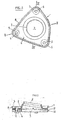
- Fig. 1 shows a thin drawn flange 1 having, in plan view, a general rounded triangular shape and comprising a collar 2, disposed obliquely and bounding an opening 3 for the passage of the gases, a main member 4 forming a gasket support surrounding the collar 2, and three clamping areas 5 each comprising a drilled hole 6.
- the main member 4 is plane and has a upward facing rim 8 adapted to make the member rigid.
- Fig. 2 shows an assembly of a thin drawn flange 1 with a manifold flange 10, with the interposition of a sealing gasket 11, the thin drawn flange 1 and the manifold flange 10 being clamped against one another, by bolts 12 inserted in their drilled holes after these holes have been aligned.
- sealing gaskets of the prior art are inappropriate for this type of flange.
- gaskets are currently produced from one or a plurality of cold-rolled stainless steel strips of European grade 1.4310 with the designation X10CrNi18.8. This material is in the basic austenitics group.
- the applicants have noted that the elastic limit of this material cold-rolled to the state C1150 according to the standard classification EN 10088-2 falls by some 40% from 1040Mpa to 680Mpa after heating at 650°C for one hour.
- the material used to produce the strip(s) adapted to form the gasket should have an elastic limit of more than 800Mpa and a degradation of the value of its elastic limit, after heating for more than one hour at a temperature of more than 500°C, of less than 14%.
- the gasket 11 is formed from at least one layer of metal sheet or strip of a thickness of between 0.1 and 0.5 mm.
- the gasket further comprises at least one opening 110 for the passage of the exhaust gases.
- the opening is bordered by a peripheral rib.
- the stainless steel of European grade 1.4571 with the designation X6CrNiMoTi17-12-2, cold-rolled to the state C1300 according to the standard classification EN 10088-2 satisfies these conditions.
- This material is in the group of austenitics with increased resistance to intergranular corrosion.
- the percentage weight contents of this stainless steel are 0.035 of C, 0.484 of Si, 1.584 of Mn, 10.595 of Ni, 16.79 of Cr, 2.04 of Mo, 0.364 of Ti, 0.11 of Cu, 0.001 of S and 0.024 of P.
- this material is normally used without cold rolling for sheathing of flues, tubes for chemistry or even flexible tubes. This material has never been used in the cold-rolled state for applications of the sealing gasket type.
- the modulus of elasticity of steel No. 1.4571 is some 1200Mpa and this value falls by only approximately 12% after heating at 650°C for 10 hours, reaching 1050Mpa.
- the sealing gasket of the invention may then be used at temperatures of between 500 and 800°C.
- gasket could therefore be made from a single layer of sheet.
- rib may be a half-rib.
- gasket of the invention has been described with reference to a thin flange with three clamping areas, the gasket of the invention also applies to any kind of exhaust flange, in particular thick flanges and/or flanges comprising two clamping areas.
Landscapes
- Engineering & Computer Science (AREA)
- General Engineering & Computer Science (AREA)
- Mechanical Engineering (AREA)
- Chemical & Material Sciences (AREA)
- Combustion & Propulsion (AREA)
- Gasket Seals (AREA)
Abstract
i, 16 to 17 of Cr, 2 to 3 of Mo and 0.36 to 0.5 of Ti, the gasket being adapted for use at temperatures of more than 500°C.
Description
Claims (6)
- A sealing gasket (11) for a thin exhaust flange (1) of a thickness comprising at least one layer of metal sheet drilled with at least one opening, each through opening being bordered by a peripheral rib, characterised in that each layer has a thickness of between 0.1 and 0.5 mm and is formed from previously cold-rolled stainless whose percentage weight contents are 0.035 to 0.039 of C, 0.4 to 0.5 of Si, 1.4 to 1.6 of Mn, 10.5 to 12.5 of Ni, 16 to 17 of Cr, 2 to 3 of Mo and 0.36 to 0.5 of Ti, the gasket being adapted for use at temperatures of more than 500°C.
- A gasket (1) as claimed in claim 1, characterised in that the steel has percentage weight contents of 0.035 of C, 0.484 of Si, 1.584 of Mn, 10.595 of Ni, 16.79 of Cr, 2.04 of Mo, 0.364 of Ti, 0.11 of Cu, 0.001 of S and 0.024 of P, with a tensile strength of more than 1300N/mm2.
- A gasket (1) as claimed in claim 1 or 2, characterised in that the gasket is adapted for use at temperatures of between 550 and 800°C.
- A gasket (1) as claimed in one of claims 1 to 3, characterised in that the gasket comprises a single layer.
- A gasket (1) as claimed in one of claims 1 to 3, characterised in that the rib is a half-rib.
- A sealing gasket as claimed in claims 1 to 5, characterised in that the state of cold rolling corresponds to the standard classification C1300 according to EN 10088-2.
Priority Applications (3)
| Application Number | Priority Date | Filing Date | Title |
|---|---|---|---|
| ES02293079T ES2292706T3 (en) | 2002-12-12 | 2002-12-12 | SEALING GASKET FOR AN EXHAUST FLANGE. |
| DE2002622681 DE60222681T2 (en) | 2002-12-12 | 2002-12-12 | Seal for exhaust flange |
| EP20020293079 EP1429057B1 (en) | 2002-12-12 | 2002-12-12 | Sealing gasket for an exhaust flange |
Applications Claiming Priority (1)
| Application Number | Priority Date | Filing Date | Title |
|---|---|---|---|
| EP20020293079 EP1429057B1 (en) | 2002-12-12 | 2002-12-12 | Sealing gasket for an exhaust flange |
Publications (2)
| Publication Number | Publication Date |
|---|---|
| EP1429057A1 true EP1429057A1 (en) | 2004-06-16 |
| EP1429057B1 EP1429057B1 (en) | 2007-09-26 |
Family
ID=32319692
Family Applications (1)
| Application Number | Title | Priority Date | Filing Date |
|---|---|---|---|
| EP20020293079 Expired - Lifetime EP1429057B1 (en) | 2002-12-12 | 2002-12-12 | Sealing gasket for an exhaust flange |
Country Status (3)
| Country | Link |
|---|---|
| EP (1) | EP1429057B1 (en) |
| DE (1) | DE60222681T2 (en) |
| ES (1) | ES2292706T3 (en) |
Cited By (1)
| Publication number | Priority date | Publication date | Assignee | Title |
|---|---|---|---|---|
| WO2008112620A1 (en) * | 2007-03-09 | 2008-09-18 | Federal-Mogul Corporation | Metal gasket |
Citations (3)
| Publication number | Priority date | Publication date | Assignee | Title |
|---|---|---|---|---|
| US5524906A (en) * | 1994-07-18 | 1996-06-11 | Mascotech Tubular Products, Inc. | Gasket for exhaust system joint |
| EP1036853A1 (en) * | 1998-09-04 | 2000-09-20 | Sumitomo Metal Industries, Ltd. | Stainless steel for engine gasket and production method therefor |
| US6491769B1 (en) * | 2000-01-24 | 2002-12-10 | Inco Alloys International, Inc. | Ni-Co-Cr high temperature strength and corrosion resistant alloy |
-
2002
- 2002-12-12 EP EP20020293079 patent/EP1429057B1/en not_active Expired - Lifetime
- 2002-12-12 DE DE2002622681 patent/DE60222681T2/en not_active Expired - Lifetime
- 2002-12-12 ES ES02293079T patent/ES2292706T3/en not_active Expired - Lifetime
Patent Citations (3)
| Publication number | Priority date | Publication date | Assignee | Title |
|---|---|---|---|---|
| US5524906A (en) * | 1994-07-18 | 1996-06-11 | Mascotech Tubular Products, Inc. | Gasket for exhaust system joint |
| EP1036853A1 (en) * | 1998-09-04 | 2000-09-20 | Sumitomo Metal Industries, Ltd. | Stainless steel for engine gasket and production method therefor |
| US6491769B1 (en) * | 2000-01-24 | 2002-12-10 | Inco Alloys International, Inc. | Ni-Co-Cr high temperature strength and corrosion resistant alloy |
Cited By (3)
| Publication number | Priority date | Publication date | Assignee | Title |
|---|---|---|---|---|
| WO2008112620A1 (en) * | 2007-03-09 | 2008-09-18 | Federal-Mogul Corporation | Metal gasket |
| CN101680064B (en) * | 2007-03-09 | 2013-12-18 | 费德罗-莫格尔公司 | metal washer |
| US9618121B2 (en) | 2007-03-09 | 2017-04-11 | Federal-Mogul Corporation | Metal gasket |
Also Published As
| Publication number | Publication date |
|---|---|
| DE60222681D1 (en) | 2007-11-08 |
| EP1429057B1 (en) | 2007-09-26 |
| DE60222681T2 (en) | 2008-06-19 |
| ES2292706T3 (en) | 2008-03-16 |
Similar Documents
| Publication | Publication Date | Title |
|---|---|---|
| US6318734B1 (en) | Gasket with integral support | |
| US7533910B2 (en) | Clamp | |
| KR101595080B1 (en) | Metal gasket and method of making | |
| US8720906B2 (en) | Gasket assembly having isolated compression limiting device | |
| EP0473306A1 (en) | Metal gasket for manifold | |
| US20110210545A1 (en) | Metal seal fitting constraints | |
| US8128128B2 (en) | Skived manifold coupler | |
| EP0665371A2 (en) | Split-type gasket | |
| WO2014071950A1 (en) | An exhaust pipe band clamp | |
| US9618121B2 (en) | Metal gasket | |
| EP1429057B1 (en) | Sealing gasket for an exhaust flange | |
| CN101245855A (en) | Laminated Gasket | |
| US20090183864A1 (en) | Heat exchanger, in particular an intercooler, comprising a reinforced pipe base | |
| EP0640782A1 (en) | Exhaust tube gasket for internal combustion engine | |
| US7896399B1 (en) | Exhaust system repair apparatus | |
| WO2004088181A1 (en) | Ring-shaped metal gasket | |
| GB2119893A (en) | Improvements in or relating to pipe repair clamps | |
| US20060162326A1 (en) | Construction of coupling exhaust pipes of vehicle | |
| US20230184356A1 (en) | Clamping system for connecting tubes, comprising a collar and a seal | |
| KR100639157B1 (en) | metal gasket | |
| EP1724546A2 (en) | Heat Exchanger | |
| CN1773086A (en) | Apparatus for connecting two waste gas duct | |
| CN218935608U (en) | Sealing flange | |
| JPH06109136A (en) | Metal gasket | |
| EP3757430A1 (en) | Laminated metal sheet |
Legal Events
| Date | Code | Title | Description |
|---|---|---|---|
| PUAI | Public reference made under article 153(3) epc to a published international application that has entered the european phase |
Free format text: ORIGINAL CODE: 0009012 |
|
| AK | Designated contracting states |
Kind code of ref document: A1 Designated state(s): AT BE BG CH CY CZ DE DK EE ES FI FR GB GR IE IT LI LU MC NL PT SE SI SK TR |
|
| AX | Request for extension of the european patent |
Extension state: AL LT LV MK RO |
|
| 17P | Request for examination filed |
Effective date: 20041020 |
|
| AKX | Designation fees paid |
Designated state(s): DE ES GB IT |
|
| RBV | Designated contracting states (corrected) |
Designated state(s): DE ES GB IT |
|
| GRAP | Despatch of communication of intention to grant a patent |
Free format text: ORIGINAL CODE: EPIDOSNIGR1 |
|
| GRAC | Information related to communication of intention to grant a patent modified |
Free format text: ORIGINAL CODE: EPIDOSCIGR1 |
|
| GRAS | Grant fee paid |
Free format text: ORIGINAL CODE: EPIDOSNIGR3 |
|
| GRAA | (expected) grant |
Free format text: ORIGINAL CODE: 0009210 |
|
| AK | Designated contracting states |
Kind code of ref document: B1 Designated state(s): DE ES GB IT |
|
| REG | Reference to a national code |
Ref country code: GB Ref legal event code: FG4D |
|
| REF | Corresponds to: |
Ref document number: 60222681 Country of ref document: DE Date of ref document: 20071108 Kind code of ref document: P |
|
| REG | Reference to a national code |
Ref country code: ES Ref legal event code: FG2A Ref document number: 2292706 Country of ref document: ES Kind code of ref document: T3 |
|
| PLBE | No opposition filed within time limit |
Free format text: ORIGINAL CODE: 0009261 |
|
| STAA | Information on the status of an ep patent application or granted ep patent |
Free format text: STATUS: NO OPPOSITION FILED WITHIN TIME LIMIT |
|
| 26N | No opposition filed |
Effective date: 20080627 |
|
| PGFP | Annual fee paid to national office [announced via postgrant information from national office to epo] |
Ref country code: GB Payment date: 20161222 Year of fee payment: 15 Ref country code: DE Payment date: 20161213 Year of fee payment: 15 |
|
| PGFP | Annual fee paid to national office [announced via postgrant information from national office to epo] |
Ref country code: ES Payment date: 20161213 Year of fee payment: 15 |
|
| PGFP | Annual fee paid to national office [announced via postgrant information from national office to epo] |
Ref country code: IT Payment date: 20161223 Year of fee payment: 15 |
|
| REG | Reference to a national code |
Ref country code: DE Ref legal event code: R119 Ref document number: 60222681 Country of ref document: DE |
|
| GBPC | Gb: european patent ceased through non-payment of renewal fee |
Effective date: 20171212 |
|
| PG25 | Lapsed in a contracting state [announced via postgrant information from national office to epo] |
Ref country code: DE Free format text: LAPSE BECAUSE OF NON-PAYMENT OF DUE FEES Effective date: 20180703 Ref country code: IT Free format text: LAPSE BECAUSE OF NON-PAYMENT OF DUE FEES Effective date: 20171212 |
|
| PG25 | Lapsed in a contracting state [announced via postgrant information from national office to epo] |
Ref country code: GB Free format text: LAPSE BECAUSE OF NON-PAYMENT OF DUE FEES Effective date: 20171212 |
|
| REG | Reference to a national code |
Ref country code: ES Ref legal event code: FD2A Effective date: 20190703 |
|
| PG25 | Lapsed in a contracting state [announced via postgrant information from national office to epo] |
Ref country code: ES Free format text: LAPSE BECAUSE OF NON-PAYMENT OF DUE FEES Effective date: 20171213 |