EP1429010A1 - DEVICE AND METHOD FOR FORMING STRATIFIED AIR−FUEL MIXTURE OF INTERNAL COMBUSTION ENGINE - Google Patents
DEVICE AND METHOD FOR FORMING STRATIFIED AIR−FUEL MIXTURE OF INTERNAL COMBUSTION ENGINE Download PDFInfo
- Publication number
- EP1429010A1 EP1429010A1 EP02762782A EP02762782A EP1429010A1 EP 1429010 A1 EP1429010 A1 EP 1429010A1 EP 02762782 A EP02762782 A EP 02762782A EP 02762782 A EP02762782 A EP 02762782A EP 1429010 A1 EP1429010 A1 EP 1429010A1
- Authority
- EP
- European Patent Office
- Prior art keywords
- fuel
- injection amount
- air
- spray
- internal combustion
- Prior art date
- Legal status (The legal status is an assumption and is not a legal conclusion. Google has not performed a legal analysis and makes no representation as to the accuracy of the status listed.)
- Withdrawn
Links
- 239000000446 fuel Substances 0.000 title claims abstract description 222
- 239000000203 mixture Substances 0.000 title claims abstract description 66
- 238000002485 combustion reaction Methods 0.000 title claims abstract description 49
- 238000000034 method Methods 0.000 title claims description 5
- 238000002347 injection Methods 0.000 claims abstract description 113
- 239000007924 injection Substances 0.000 claims abstract description 113
- 239000007921 spray Substances 0.000 claims abstract description 80
- 230000001276 controlling effect Effects 0.000 claims description 10
- 230000001105 regulatory effect Effects 0.000 claims description 6
- 239000007789 gas Substances 0.000 description 14
- 238000010586 diagram Methods 0.000 description 12
- 101150028668 APO1 gene Proteins 0.000 description 3
- 230000006835 compression Effects 0.000 description 2
- 238000007906 compression Methods 0.000 description 2
- 238000009792 diffusion process Methods 0.000 description 2
- 230000000694 effects Effects 0.000 description 2
- 239000000498 cooling water Substances 0.000 description 1
- 230000007423 decrease Effects 0.000 description 1
- 238000006073 displacement reaction Methods 0.000 description 1
- 238000005265 energy consumption Methods 0.000 description 1
- 239000002828 fuel tank Substances 0.000 description 1
- 230000002093 peripheral effect Effects 0.000 description 1
- 238000011144 upstream manufacturing Methods 0.000 description 1
- XLYOFNOQVPJJNP-UHFFFAOYSA-N water Substances O XLYOFNOQVPJJNP-UHFFFAOYSA-N 0.000 description 1
Images


Classifications
-
- F—MECHANICAL ENGINEERING; LIGHTING; HEATING; WEAPONS; BLASTING
- F02—COMBUSTION ENGINES; HOT-GAS OR COMBUSTION-PRODUCT ENGINE PLANTS
- F02M—SUPPLYING COMBUSTION ENGINES IN GENERAL WITH COMBUSTIBLE MIXTURES OR CONSTITUENTS THEREOF
- F02M61/00—Fuel-injectors not provided for in groups F02M39/00 - F02M57/00 or F02M67/00
- F02M61/16—Details not provided for in, or of interest apart from, the apparatus of groups F02M61/02 - F02M61/14
- F02M61/162—Means to impart a whirling motion to fuel upstream or near discharging orifices
-
- F—MECHANICAL ENGINEERING; LIGHTING; HEATING; WEAPONS; BLASTING
- F02—COMBUSTION ENGINES; HOT-GAS OR COMBUSTION-PRODUCT ENGINE PLANTS
- F02D—CONTROLLING COMBUSTION ENGINES
- F02D41/00—Electrical control of supply of combustible mixture or its constituents
- F02D41/30—Controlling fuel injection
- F02D41/3011—Controlling fuel injection according to or using specific or several modes of combustion
- F02D41/3017—Controlling fuel injection according to or using specific or several modes of combustion characterised by the mode(s) being used
- F02D41/3023—Controlling fuel injection according to or using specific or several modes of combustion characterised by the mode(s) being used a mode being the stratified charge spark-ignited mode
- F02D41/3029—Controlling fuel injection according to or using specific or several modes of combustion characterised by the mode(s) being used a mode being the stratified charge spark-ignited mode further comprising a homogeneous charge spark-ignited mode
-
- F—MECHANICAL ENGINEERING; LIGHTING; HEATING; WEAPONS; BLASTING
- F02—COMBUSTION ENGINES; HOT-GAS OR COMBUSTION-PRODUCT ENGINE PLANTS
- F02M—SUPPLYING COMBUSTION ENGINES IN GENERAL WITH COMBUSTIBLE MIXTURES OR CONSTITUENTS THEREOF
- F02M67/00—Apparatus in which fuel-injection is effected by means of high-pressure gas, the gas carrying the fuel into working cylinders of the engine, e.g. air-injection type
- F02M67/02—Apparatus in which fuel-injection is effected by means of high-pressure gas, the gas carrying the fuel into working cylinders of the engine, e.g. air-injection type the gas being compressed air, e.g. compressed in pumps
-
- F—MECHANICAL ENGINEERING; LIGHTING; HEATING; WEAPONS; BLASTING
- F02—COMBUSTION ENGINES; HOT-GAS OR COMBUSTION-PRODUCT ENGINE PLANTS
- F02M—SUPPLYING COMBUSTION ENGINES IN GENERAL WITH COMBUSTIBLE MIXTURES OR CONSTITUENTS THEREOF
- F02M67/00—Apparatus in which fuel-injection is effected by means of high-pressure gas, the gas carrying the fuel into working cylinders of the engine, e.g. air-injection type
- F02M67/10—Injectors peculiar thereto, e.g. valve less type
- F02M67/12—Injectors peculiar thereto, e.g. valve less type having valves
-
- F—MECHANICAL ENGINEERING; LIGHTING; HEATING; WEAPONS; BLASTING
- F02—COMBUSTION ENGINES; HOT-GAS OR COMBUSTION-PRODUCT ENGINE PLANTS
- F02B—INTERNAL-COMBUSTION PISTON ENGINES; COMBUSTION ENGINES IN GENERAL
- F02B75/00—Other engines
- F02B75/12—Other methods of operation
- F02B2075/125—Direct injection in the combustion chamber for spark ignition engines, i.e. not in pre-combustion chamber
-
- F—MECHANICAL ENGINEERING; LIGHTING; HEATING; WEAPONS; BLASTING
- F02—COMBUSTION ENGINES; HOT-GAS OR COMBUSTION-PRODUCT ENGINE PLANTS
- F02B—INTERNAL-COMBUSTION PISTON ENGINES; COMBUSTION ENGINES IN GENERAL
- F02B23/00—Other engines characterised by special shape or construction of combustion chambers to improve operation
- F02B23/08—Other engines characterised by special shape or construction of combustion chambers to improve operation with positive ignition
- F02B23/10—Other engines characterised by special shape or construction of combustion chambers to improve operation with positive ignition with separate admission of air and fuel into cylinder
- F02B23/101—Other engines characterised by special shape or construction of combustion chambers to improve operation with positive ignition with separate admission of air and fuel into cylinder the injector being placed on or close to the cylinder centre axis, e.g. with mixture formation using spray guided concepts
-
- F—MECHANICAL ENGINEERING; LIGHTING; HEATING; WEAPONS; BLASTING
- F02—COMBUSTION ENGINES; HOT-GAS OR COMBUSTION-PRODUCT ENGINE PLANTS
- F02D—CONTROLLING COMBUSTION ENGINES
- F02D41/00—Electrical control of supply of combustible mixture or its constituents
- F02D41/30—Controlling fuel injection
- F02D41/3011—Controlling fuel injection according to or using specific or several modes of combustion
-
- F—MECHANICAL ENGINEERING; LIGHTING; HEATING; WEAPONS; BLASTING
- F02—COMBUSTION ENGINES; HOT-GAS OR COMBUSTION-PRODUCT ENGINE PLANTS
- F02M—SUPPLYING COMBUSTION ENGINES IN GENERAL WITH COMBUSTIBLE MIXTURES OR CONSTITUENTS THEREOF
- F02M39/00—Arrangements of fuel-injection apparatus with respect to engines; Pump drives adapted to such arrangements
- F02M39/02—Arrangements of fuel-injection apparatus to facilitate the driving of pumps; Arrangements of fuel-injection pumps; Pump drives
-
- Y—GENERAL TAGGING OF NEW TECHNOLOGICAL DEVELOPMENTS; GENERAL TAGGING OF CROSS-SECTIONAL TECHNOLOGIES SPANNING OVER SEVERAL SECTIONS OF THE IPC; TECHNICAL SUBJECTS COVERED BY FORMER USPC CROSS-REFERENCE ART COLLECTIONS [XRACs] AND DIGESTS
- Y02—TECHNOLOGIES OR APPLICATIONS FOR MITIGATION OR ADAPTATION AGAINST CLIMATE CHANGE
- Y02T—CLIMATE CHANGE MITIGATION TECHNOLOGIES RELATED TO TRANSPORTATION
- Y02T10/00—Road transport of goods or passengers
- Y02T10/10—Internal combustion engine [ICE] based vehicles
- Y02T10/12—Improving ICE efficiencies
Definitions
- the present invention relates to an internal combustion engine in which fuel is directly injected into a cylinder to be burned by spark ignition.
- a range in which a stratified air-fuel mixture is formed (the size of an air-fuel mixture mass) is mainly determined depending on the size of a cavity, an air-fuel ratio of the air-fuel mixture becomes lean when an engine load is low (a fuel injection amount is small) while the air-fuel ratio of the air-fuel mixture becomes rich when the engine load is high (the fuel injection amount is large).
- a range of the load condition under which the air-fuel mixture of an appropriate air-fuel ratio (in the vicinity of a stoichiometric air-fuel ratio) can be formed is determined depending on the size of the cavity, it is difficult to carry out stratified combustion operation under a wide load condition.
- the present invention has been accomplished in view of the above problem and it is an object of the invention to provide a stratified air-fuel mixture forming apparatus and a method thereof, capable of forming a stratified air-fuel mixture of an appropriate air-fuel ratio under a broad load condition.
- a stratified air-fuel mixture forming apparatus for an internal combustion engine in which a spark plug is disposed substantially at the center of an upper portion of a combustion chamber comprises a fuel injecting device which forms a fuel spray moving toward a piston reciprocating in a cylinder, and a control device which controls the momentum of the fuel spray according to a fuel injection amount so that an increase rate of the momentum of the fuel spray in an axial direction of the cylinder is greater than that of the fuel injection amount.
- FIG. 1 is a system diagram showing a constitution of a first embodiment of a direct-injection spark ignition internal combustion engine according to the present invention.
- This internal combustion engine includes a combustion chamber 4 defined by a cylinder head 1, a cylinder block 2, and a piston 3, and takes in fresh air from an intake port 7 through an intake valve 5 and discharges exhaust from an exhaust port 8 through an exhaust valve 6.
- a bowl portion 3b is formed on a portion, which faces the air-fuel mixture injection valve 9, of the piston 3.
- the injected air-fuel mixture is form in a stratified air-fuel mixture mass mainly in and above the bowl portion 3b.
- the air-fuel mixture mass is ignited and burned by a spark plug 10 disposed substantially at the center of the upper portion of the combustion chamber 4.
- a fuel injection system will be described in detail.
- a fuel pump 11 driven by the camshaft 6a is disposed at an end portion of a camshaft 6a driving the exhaust valve 6, a fuel pump 11 driven by the camshaft 6a is disposed.
- the fuel pump 11 pumps the fuel out of a fuel tank, to supply the fuel to the air-fuel mixture injection valve 9 through fuel piping 12.
- a fuel pressure in the fuel piping 12 is always maintained at a constant pressure.
- an air pump 13 driven by the camshaft 5a is disposed at an end portion of a camshaft 5a driving the intake valve 5.
- the air pump 13 pumps the air out of an intake collector, to supply the air to the air-fuel mixture injection valve 9 through air piping 14.
- An air pressure in the air piping 14 can be regulated to an arbitrary pressure by a pressure control valve (gas pressure regulator) 13b.
- the two pumps may be driven by one of the camshafts or may be driven by an electric motor disposed separately.
- the air-fuel mixture injection valve 9 as shown in a schematic structural diagram of FIG.2, consists of a main injector (gas injection valve) 21 facing inside the combustion chamber 4 and a subsidiary injector 22 facing an air-fuel mixture chamber 21a of the main injector 21.
- the air-fuel mixture chamber 21a to which the air piping 14 is connected, is in the main injector 21 being a main body of the air-fuel mixture injection valve 9.
- the air-fuel mixture chamber 21a is connected to a nozzle hole 21b, which faces inside the combustion chamber, of the main injector 21.
- the nozzle hole 21b is opened and closed by an electro-magnetically driven needle valve 21c.
- the fuel piping 12 is connected to the subsidiary injector 22 and a nozzle hole 22b of the subsidiary injector 22 faces the air-fuel mixture chamber 21a of the main injector 21.
- the nozzle hole 22b is opened and closed by an electro-magnetically driven needle valve 22c.
- the air pressurized by the air pump 13 is led into the air-fuel mixture chamber 21a of the main injector 21.
- the needle valve 22c of the subsidiary injector 22 is driven to open, the fuel pressurized by the fuel pump 11 is injected into the air-fuel mixture chamber 21a, and the injected fuel is mixed with the high-pressure air in the air-fuel mixture chamber 21a, to form an air-fuel mixture.
- the air-fuel mixture is injected into the combustion chamber 4 when the needle valve 21c of the main injector 21 is driven to open.
- the structure of the fuel injecting device is relatively simple, resulting in that the designing around the combustion chamber is easy.
- the present invention can also be realized in such a fuel injecting device in which a fuel injection system and an air injection system are independent of each other, and fuel and air are separately injected into a combustion chamber (with two nozzle holes formed adjacent to each other).
- This internal combustion engine is controlled in an integrated manner by an engine control unit (hereinafter referred to as ECU) 15 being a control device.
- the ECU 15 receives signals from a crank angle sensor 16 outputting a signal at each time a crankshaft is rotated by a predetermined angle (for example, 1° ), an accelerator opening sensor 17 outputting a signal corresponding to a depression amount of an accelerator pedal, a water temperature sensor 18 outputting a signal corresponding to a temperature of engine cooling water and the like.
- the ECU 15 performs necessary operations and processing therein, to control the air-fuel mixture injection valve 9, the spark plug 10, the pressure control valve 13b and the like.
- the needle valve 22c of the subsidiary injector 22 and the needle valve 21c of the main injector 21 can be controlled independently in the air-fuel mixture injection valve 9.
- FIG. 3 is a control flowchart showing a processing routine executed by the ECU 15 at each predetermined time (for example, 10ms). In this routine, control values for controlling the air-fuel mixture injection valve 9 and the pressure control valve 13b are calculated.
- an engine rotational speed Ne and an accelerator opening APO are read from a memory in the ECU 15.
- the ECU 15 calculates the engine rotational speed Ne sequentially based on the signals from the crank angle sensor 16, and the latest value is stored in the memory in the ECU 15.
- Output signals (APO) from the accelerator opening sensor 17 are sampled in a predetermined cycle, and the latest value is stored in the memory in the ECU 15.
- the accelerator opening APO is a parameter representing an engine load.
- injection timing ITa and opening time Ta of the main injector 21, and a target air pressure Pa of the pressure control valve 13b are calculated based on the engine rotational speed Ne and the accelerator opening APO.
- respective values corresponding to the current Ne and APO are looked up in a control map in which ITa, Ta, and Pa are stored so as to correspond to the engine rotational speed and the accelerator opening.
- a stratified combustion is performed in a low-rotation and low-load area and a homogeneous combustion is performed in an area other than the low-rotation and low-load area.
- the injection timing ITa for when engine operating conditions (Ne, APO) are in the stratified combustion area is set in the latter half of a compression stroke, and the injection timing ITa for when the engine operating conditions are in the homogeneous combustion area, is set in an intake stroke. Furthermore, the injection timing ITa in the stratified combustion area is set to an advance side as the engine load (accelerator opening APO) increases.
- injection timing ITf and opening time Tf of the subsidiary injector 22 are calculated based on the engine rotational speed Ne and the accelerator opening APO.
- respective values corresponding to the current Ne and APO are looked up in a control map in which ITf and Tf are stored so as to correspond to the engine rotational speed and the accelerator opening.
- the injection timing ITf of the subsidiary injector 22 is set to a slightly further advance side than the injection timing ITa of the main injector 21.
- the respective control values calculated as described above are once stored in the memory in the ECU 15, and then used to control the air-fuel mixture injection valve 9 and the pressure control valve 13b.
- a valve opening signal of pulse width corresponding to the opening time Tf is sent to the subsidiary injector 22 of the air-fuel mixture injection valve 9, and at a crank angle corresponding to the injection timing ITa, a valve opening signal of pulse width corresponding to the opening time Ta is sent to the main injector 21 of the air-fuel mixture injection valve 9, and a control signal for coinciding the air pressure in the air piping 14 with the target air pressure Pa is sent to the pressure control valve 13b.
- FIG. 7 schematically shows a process of forming the stratified air-fuel mixture in the combustion chamber in the present embodiment.
- the spray injected from the air-fuel'mixture injection valve 9 toward the bowl portion 3b on the top surface of the piston 3 remains in the bowl portion 3b, to be diffused and mixed in the bowl portion 3b. Therefore, the size of the stratified air-fuel mixture mass becomes relatively small and the air-fuel ratio of the air-fuel mixture can be maintained in a desired range even if the fuel injection amount is small.
- the spray injected from the air-fuel mixture injection valve 9 toward the bowl portion 3b on the top face of the piston 3 collides with an inner wall of the bowl portion 3b, then rolls up by a large amount due to its momentum, and is diffused and mixed while mixing up the air above the bowl portion 3b.
- the size of the stratified air-fuel mixture mass becomes relatively large and the air-fuel ratio of the air-fuel mixture can be maintained in the desired range even if the fuel injection amount is large.
- the fuel injecting device (air-fuel mixture injection valve 9) includes the gas injection valve (main injector 21) injecting gas toward the piston, and is configured to form the injected gas (air) and the fuel into the fuel spray, the spray momentum in the axial direction of the cylinder can reliably be controlled according to the load by controlling the gas injection amount (the opening time Ta) and also the gas pressure (the air pressure Pa), while enabling the control of the spray momentum in the axial direction of the cylinder by only controlling the gas,.
- the gas injection valve main injector 21
- the spray momentum in the axial direction of the cylinder can reliably be controlled according to the load by controlling the gas injection amount (the opening time Ta) and also the gas pressure (the air pressure Pa), while enabling the control of the spray momentum in the axial direction of the cylinder by only controlling the gas,.
- the air pressure Pa it is also possible to set the air pressure Pa to be constant irrespective of the load and to increase the opening time Ta of the main injector 21 according to the rise of the load, to thereby make the increase rate of the spray momentum greater than that of the fuel injection amount.
- the pressure control valve 13b can be omitted.
- the spray momentum is made to sufficiently increase only by increasing the opening time Ta, the opening time Ta at the high load becomes extremely long. Therefore, it becomes necessary to advance largely the injection timing ITa of the main injector 21 at the high load, resulting in that it is difficult to form the stratified air-fuel mixture mass in the bowl portion 3b of the piston 3. Consequently, a preferable stratified combustion can be obtained under the broader engine operating condition if the air pressure Pa is also increased.
- the air injection amount Ma in the homogeneous area is relatively small in the present embodiment, it is possible to reduce energy consumption in actuation of the air pump 13.
- the air injection amount Ma in the homogeneous area is constant irrespective of the load in this embodiment, the air injection amount Ma may be set so that a ratio between the air injection amount Ma and the fuel injection amount Mf becomes constant, for example, to maintain the air-fuel ratio of the spray in the homogeneous to be substantially constant.
- the higher the engine rotational speed the stronger a flow (turbulence) of gas in the combustion chamber becomes. Accordingly, the higher the engine rotational speed, the spray is likely to be diffused. Therefore, the spray momentum is set to increase as the engine rotational speed increases under the same load condition, to thereby prevent excessive diffusion of the spray during the operation at a high rotational speed.
- the gas flow may not develop to the extent of exerting a large influence on diffusion of the spray in some cases.
- FIG. 8 is a system diagram showing a constitution of the second embodiment.
- an injector (fuel injection valve) 30 singly injecting fuel is used as a fuel injecting device. Therefore, the system does not include the air pump as in the first embodiment.
- the constitution of the second embodiment differs from that of the first embodiment in that the fuel pump 11 is disposed at an end portion of the camshaft 5a driving the intake valve 5 and a fuel pressure control valve (fuel pressure regulator) 11b capable of regulating the fuel pressure in the fuel piping 12 to an arbitrary pressure is provided.
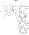
- the injector 30 is a swirl injector in which swirl chips are disposed around a needle valve 30c opening and closing a nozzle hole 30b as shown in a schematic structural diagram in FIG. 9.
- the swirl chips of the injector 30 consist of four parts 31 to 34.
- the part 31 on the most upstream side is a cylindrical part which is provided with a hole 31a of a slightly larger diameter than a diameter of the needle valve 30c on a center thereof, and axially extending four fuel passage grooves 31b on an outer peripheral face thereof.
- the part 32 adjacent to the part 31 is a disc-shaped part which is provided with a hole 32a similar to the part 31 and fuel passage grooves 32b communicating with the fuel passage grooves 31b of the part 31. Radial fuel passage grooves 32c connecting the hole 32a to the fuel passage grooves 32b are formed on an end face of the part 32.
- the part 33 adjacent to the part 32 is similar to the part 32.
- each of radial fuel passage grooves 33b of the part 33 is formed so as to be at a predetermined angle to the radial direction.
- the part 34 closest to a tip end is also similar to the part 32 or the part 33.
- angles at which radial fuel passage grooves 34b of the part 34 are formed are greater than those of the radial fuel passage grooves 33b of the part 33.
- the needle valve 30c is driven by a piezo actuator and controls magnitude (voltage) of the valve opening signal, to thereby achieve an arbitrary lift amount. If an electro-magnetic coil actuator is used, one valve opening signal can be split into a plurality of small pulses to be sent to the actuator, and the lift amount can be regulated by controlling the width of each small pulse.
- FIG. 10 is a control flowchart showing a processing routine executed by the ECU 15 at each predetermined time (for example, 10ms). In this routine, control values for controlling the injector 30 and fuel pressure control valve 11b are calculated.
- step 11 the engine rotational speed Ne and the accelerator opening APO are read from the memory in the ECU 15.
- injection timing ITf, a lift amount Lf of the needle valve 30c and an opening time Tf, of the injector 30, and a target fuel pressure Pf of the fuel pressure control valve 11b are calculated based on the engine rotational speed Ne and the accelerator opening APO.
- the respective values corresponding to the current Ne and APO are looked up in a control map in which ITf, Lf, Tf and Pf are stored so as to correspond to the engine rotational speed and the accelerator opening.
- the respective control values calculated as described above are once stored in the memory in the ECU 15, and then used to control the injector 30 and the fuel pressure control valve 11b.
- the fuel injecting device can be formed of the fuel injection valve (injector 30) only, and the structure can be simplified.
- the spray momentum in the axial direction of the cylinder can reliably be controlled according to the load.
- the increase rate of the spray momentum in the axial direction of the cylinder is made greater than that of the fuel injection amount by increasing the fuel pressure Pf only or the lift amount Lf only, according to the load.
- the stratified air-fuel mixture of the appropriate air-fuel ratio can be formed under the broad load condition, and the area of the stratified combustion operation can be broadened. Consequently, the present invention has a wide range of industrial applications.
Landscapes
- Engineering & Computer Science (AREA)
- Chemical & Material Sciences (AREA)
- Combustion & Propulsion (AREA)
- Mechanical Engineering (AREA)
- General Engineering & Computer Science (AREA)
- Electrical Control Of Air Or Fuel Supplied To Internal-Combustion Engine (AREA)
- Fuel-Injection Apparatus (AREA)
- Combustion Methods Of Internal-Combustion Engines (AREA)
Abstract
In the present invention, in a direct-injection spark ignition
internal combustion engine, an air-fuel mixture mass of appropriate
density and size is formed in a combustion chamber having a piston bowl
with fixed volume, according to an operating condition of the engine.
For this purpose, a fuel injection amount is increased according to a rise
of an engine load, the momentum of a fuel spray in the axial direction of
a cylinder is increased, and also an increase rate of the momentum of a
fuel spray in an axial direction of a cylinder is made greater than that of
the fuel injection amount.
Description
- The present invention relates to an internal combustion engine in which fuel is directly injected into a cylinder to be burned by spark ignition.
- There is an internal combustion engine in which fuel is injected from an upper portion of a combustion chamber toward a cavity formed in a top surface of a piston to form a stratified air-fuel mixture in the cavity and in a space above the cavity, and the stratified air-fuel mixture is burned by spark ignition as disclosed in Japanese Unexamined Patent Publication No. 11-82028.
- Since a range in which a stratified air-fuel mixture is formed (the size of an air-fuel mixture mass) is mainly determined depending on the size of a cavity, an air-fuel ratio of the air-fuel mixture becomes lean when an engine load is low (a fuel injection amount is small) while the air-fuel ratio of the air-fuel mixture becomes rich when the engine load is high (the fuel injection amount is large). In other words, since a range of the load condition under which the air-fuel mixture of an appropriate air-fuel ratio (in the vicinity of a stoichiometric air-fuel ratio) can be formed is determined depending on the size of the cavity, it is difficult to carry out stratified combustion operation under a wide load condition.
- The present invention has been accomplished in view of the above problem and it is an object of the invention to provide a stratified air-fuel mixture forming apparatus and a method thereof, capable of forming a stratified air-fuel mixture of an appropriate air-fuel ratio under a broad load condition.
- For this object, in the present invention, a stratified air-fuel mixture forming apparatus for an internal combustion engine in which a spark plug is disposed substantially at the center of an upper portion of a combustion chamber, comprises a fuel injecting device which forms a fuel spray moving toward a piston reciprocating in a cylinder, and a control device which controls the momentum of the fuel spray according to a fuel injection amount so that an increase rate of the momentum of the fuel spray in an axial direction of the cylinder is greater than that of the fuel injection amount.
- With such a constitution; a range in which the stratified air-fuel mixture is formed can be widened positively as the fuel injection amount (engine load) increases. As a result, it is possible to form the air-fuel mixture of the appropriate air-fuel ratio under the broad load condition.
- Characteristic structures and operation and effects based on them of the present invention will become more apparent by the following embodiments.
-
- FIG. 1 is a system diagram of a first embodiment of the present invention.
- FIG. 2 is a schematic structural diagram of an air-fuel mixture injection valve.
- FIG. 3 is a flowchart showing a routine of control.
- FIG. 4 is a diagram showing the switching of combustion modes with respect to rotation and a load.
- FIG. 5 is a diagram showing setting characteristics of control values and a spray characteristic.
- FIG. 6 is a time chart of fuel and air injection.
- FIG. 7 is a diagram showing a process of forming an air-fuel mixture in a cylinder.
- FIG. 8 is a system diagram of a second embodiment of the invention.
- FIG. 9 is a schematic structural diagram of an injector.
- FIG. 10 is a flowchart showing a routine of control in the second embodiment.
- FIG. 11 is a diagram showing setting characteristics of control values and a spray characteristic in the second embodiment.
-
- Embodiments of the present invention will be described below based on the drawings.
- FIG. 1 is a system diagram showing a constitution of a first embodiment of a direct-injection spark ignition internal combustion engine according to the present invention.
- This internal combustion engine includes a
combustion chamber 4 defined by acylinder head 1, acylinder block 2, and a piston 3, and takes in fresh air from anintake port 7 through anintake valve 5 and discharges exhaust from anexhaust port 8 through anexhaust valve 6. - An air-fuel mixture injection valve (fuel injecting device) 9, which is disposed substantially at the center of an upper portion of the
combustion chamber 4, can inject a mixture of air and fuel in the form of a spray symmetric with respect to a cylinder axis, toward the piston 3. Abowl portion 3b is formed on a portion, which faces the air-fuelmixture injection valve 9, of the piston 3. The injected air-fuel mixture is form in a stratified air-fuel mixture mass mainly in and above thebowl portion 3b. The air-fuel mixture mass is ignited and burned by aspark plug 10 disposed substantially at the center of the upper portion of thecombustion chamber 4. - A fuel injection system will be described in detail.
- At an end portion of a
camshaft 6a driving theexhaust valve 6, afuel pump 11 driven by thecamshaft 6a is disposed. Thefuel pump 11 pumps the fuel out of a fuel tank, to supply the fuel to the air-fuelmixture injection valve 9 throughfuel piping 12. A fuel pressure in thefuel piping 12 is always maintained at a constant pressure. - On the other hand, at an end portion of a
camshaft 5a driving theintake valve 5, anair pump 13 driven by thecamshaft 5a is disposed. Theair pump 13 pumps the air out of an intake collector, to supply the air to the air-fuelmixture injection valve 9 throughair piping 14. An air pressure in theair piping 14 can be regulated to an arbitrary pressure by a pressure control valve (gas pressure regulator) 13b. - Here, the two pumps may be driven by one of the camshafts or may be driven by an electric motor disposed separately.
- The air-fuel
mixture injection valve 9, as shown in a schematic structural diagram of FIG.2, consists of a main injector (gas injection valve) 21 facing inside thecombustion chamber 4 and asubsidiary injector 22 facing an air-fuel mixture chamber 21a of themain injector 21. - In other words, the air-
fuel mixture chamber 21a, to which theair piping 14 is connected, is in themain injector 21 being a main body of the air-fuelmixture injection valve 9. The air-fuel mixture chamber 21a is connected to anozzle hole 21b, which faces inside the combustion chamber, of themain injector 21. Thenozzle hole 21b is opened and closed by an electro-magnetically drivenneedle valve 21c. - The
fuel piping 12 is connected to thesubsidiary injector 22 and anozzle hole 22b of thesubsidiary injector 22 faces the air-fuel mixture chamber 21a of themain injector 21. Thenozzle hole 22b is opened and closed by an electro-magnetically drivenneedle valve 22c. - Accordingly, the air pressurized by the
air pump 13 is led into the air-fuel mixture chamber 21a of themain injector 21. When theneedle valve 22c of thesubsidiary injector 22 is driven to open, the fuel pressurized by thefuel pump 11 is injected into the air-fuel mixture chamber 21a, and the injected fuel is mixed with the high-pressure air in the air-fuel mixture chamber 21a, to form an air-fuel mixture. The air-fuel mixture is injected into thecombustion chamber 4 when theneedle valve 21c of themain injector 21 is driven to open. - In the present embodiment, since the constitution is such that the fuel and air are injected into the combustion chamber by means of one air-fuel mixture injection valve, the structure of the fuel injecting device is relatively simple, resulting in that the designing around the combustion chamber is easy. However, the present invention can also be realized in such a fuel injecting device in which a fuel injection system and an air injection system are independent of each other, and fuel and air are separately injected into a combustion chamber (with two nozzle holes formed adjacent to each other). Moreover, it is also possible to realize the present invention by disposing an injection valve injecting fuel only and an injection valve injecting air only adjacent to each other.
- Next, a control system of the present embodiment will be described.
- This internal combustion engine is controlled in an integrated manner by an engine control unit (hereinafter referred to as ECU) 15 being a control device. For this purpose, the
ECU 15 receives signals from acrank angle sensor 16 outputting a signal at each time a crankshaft is rotated by a predetermined angle (for example, 1° ), anaccelerator opening sensor 17 outputting a signal corresponding to a depression amount of an accelerator pedal, awater temperature sensor 18 outputting a signal corresponding to a temperature of engine cooling water and the like. The ECU 15 performs necessary operations and processing therein, to control the air-fuelmixture injection valve 9, thespark plug 10, thepressure control valve 13b and the like. At this time, theneedle valve 22c of thesubsidiary injector 22 and theneedle valve 21c of themain injector 21 can be controlled independently in the air-fuelmixture injection valve 9. - FIG. 3 is a control flowchart showing a processing routine executed by the
ECU 15 at each predetermined time (for example, 10ms). In this routine, control values for controlling the air-fuelmixture injection valve 9 and thepressure control valve 13b are calculated. - First, at step 1 (S1 in the drawing and succeeding steps are abbreviated similarly), an engine rotational speed Ne and an accelerator opening APO are read from a memory in the
ECU 15. The ECU 15 calculates the engine rotational speed Ne sequentially based on the signals from thecrank angle sensor 16, and the latest value is stored in the memory in theECU 15. Output signals (APO) from theaccelerator opening sensor 17 are sampled in a predetermined cycle, and the latest value is stored in the memory in theECU 15. The accelerator opening APO is a parameter representing an engine load. - Next, at
step 2, injection timing ITa and opening time Ta of themain injector 21, and a target air pressure Pa of thepressure control valve 13b, are calculated based on the engine rotational speed Ne and the accelerator opening APO. To be specific, respective values corresponding to the current Ne and APO are looked up in a control map in which ITa, Ta, and Pa are stored so as to correspond to the engine rotational speed and the accelerator opening. As shown in FIG. 4, in the present embodiment, a stratified combustion is performed in a low-rotation and low-load area and a homogeneous combustion is performed in an area other than the low-rotation and low-load area. Therefore, the injection timing ITa for when engine operating conditions (Ne, APO) are in the stratified combustion area, is set in the latter half of a compression stroke, and the injection timing ITa for when the engine operating conditions are in the homogeneous combustion area, is set in an intake stroke. Furthermore, the injection timing ITa in the stratified combustion area is set to an advance side as the engine load (accelerator opening APO) increases. - Next, at step 3, injection timing ITf and opening time Tf of the
subsidiary injector 22 are calculated based on the engine rotational speed Ne and the accelerator opening APO. To be specific, respective values corresponding to the current Ne and APO are looked up in a control map in which ITf and Tf are stored so as to correspond to the engine rotational speed and the accelerator opening. Here, the injection timing ITf of thesubsidiary injector 22 is set to a slightly further advance side than the injection timing ITa of themain injector 21. - The respective control values calculated as described above are once stored in the memory in the
ECU 15, and then used to control the air-fuelmixture injection valve 9 and thepressure control valve 13b. To be specific, at a crank angle corresponding to the injection timing ITf, a valve opening signal of pulse width corresponding to the opening time Tf is sent to thesubsidiary injector 22 of the air-fuelmixture injection valve 9, and at a crank angle corresponding to the injection timing ITa, a valve opening signal of pulse width corresponding to the opening time Ta is sent to themain injector 21 of the air-fuelmixture injection valve 9, and a control signal for coinciding the air pressure in the air piping 14 with the target air pressure Pa is sent to thepressure control valve 13b. - Next, setting characteristics of the respective control values calculated in the routine of FIG. 3 and a spray characteristic due to the setting characteristics will be described referring to FIG. 5. The respective control values and the spray characteristic under a condition that the engine rotational speed is constant (Ne1 in FIG. 4) are shown in FIG. 5.
- A) of FIG. 5 shows the settings of the opening time Ta of the
main injector 21 and the opening time Tf of thesubsidiary injector 22. The opening time Tf of thesubsidiary injector 22 is set to increase as the load increases. The opening time Ta of themain injector 21 is set to increase as the load increases in the stratified area, while being set to a relatively short and constant time irrespective of the load in the homogeneous area. An increase rate of the opening time Ta of themain injector 21 in the stratified area is greater than that of the opening time Tf of thesubsidiary injector 22, and therefore, a ratio of the opening time Ta to the opening time Tf increases as the load increases. A) of FIG. 6 shows operation time charts of the main andsubsidiary injectors subsidiary injectors - B) of FIG. 5 shows a fuel pressure Pf in the
fuel piping 12, an air pressure Pa in the air piping 14, and a pressure Pit in thecombustion chamber 4 at the injection timing ITa of themain injector 21. The fuel pressure Pf is always maintained at a constant pressure. The air pressure Pa is set to increase as the load increases in the stratified area, while being set to a relatively low and constant pressure irrespective of the load in the homogeneous area. Further, the injection timing ITa of themain injector 21 is set in the latter half of the compression stroke and to the advance side as the load increases in the stratified area, and is set in the intake stroke in the homogeneous area. Therefore, the pressure Pita in the combustion chamber at the injection timing ITa decreases as the load increases in the stratified area, and is constant (in the vicinity of atmospheric pressure) irrespective of the load in the homogeneous area. - C) of FIG. 5 shows a spray velocity Vaf at the injection timing ITa
of the
main injector 21. In the present embodiment, a velocity Va of the air injected from themain injector 21 is the spray velocity Vaf, and the injected air velocity Va increases as a difference between the air pressure Pa and the pressure Pita in the combustion chamber increases. Accordingly, the spray velocity Vaf increases as the load increases in the stratified area, while being substantially constant in the homogeneous area. - D) of FIG. 5 shows a fuel injection amount Mf, an air injection
amount Ma, and a total amount Maf of the injected air and fuel. The fuel
injection amount Mf is determined based on the fuel pressure Pf and the
opening time Tf of the
subsidiary injector 22. Consequently, the fuel injection amount Mf increases as the load increases. Further, the air injection amount Ma is determined based on the injected air velocity Va and the opening time Ta of themain injector 21. Consequently, the air injection amount Ma increases as the load increases in the stratified area, while being substantially constant in the homogeneous area. An increase rate of the air injection amount Ma is greater than that of the fuel injection amount Mf in the stratified area, and therefore, a ratio of the air injection amount Ma to the fuel injection amount Mf increases as the load increases. - E) of FIG. 5 shows the spray momentum and the fuel injection amount. The spray momentum is determined based on the spray velocity Vaf and the air-fuel total injection amount Maf. Accordingly, the spray momentum considerably increases as the load increases in the stratified area, while slightly increasing as the load increases in the homogeneous area. Here, the spray momentum in this figure is a dimensionless value (=spray momentum/minimum spray momentum) obtained by using the minimum spray momentum (spray momentum at APO1), and the fuel injection amount is similarly a dimensionless value (=fuel injection amount Mf/minimum fuel injection amount) obtained by using the minimum fuel injection amount (fuel injection amount at APO1). As is apparent from figure, an increase rate of the spray momentum is greater than that of the fuel injection amount in the stratified area. Since a spray injecting direction or a shape of the spray does not change in this embodiment, an increase rate of the momentum of the whole spray and an increase rate of the spray momentum in an axial direction of the cylinder are substantially equal to each other. Accordingly, the increase rate of the spray momentum in the axial direction of the cylinder is greater than that of the fuel injection amount. To specifically describe the case in this figure, the spray momentum increases up to about twice the minimum spray momentum under the load condition (APO2) that the fuel injection amount increases by about 25% from the minimum fuel injection amount.
-
- FIG. 7 schematically shows a process of forming the stratified air-fuel mixture in the combustion chamber in the present embodiment.
- Since the spray momentum in the axial direction of the cylinder is small at the low load with a small fuel injection amount, the spray injected from the air-
fuel'mixture injection valve 9 toward thebowl portion 3b on the top surface of the piston 3 remains in thebowl portion 3b, to be diffused and mixed in thebowl portion 3b. Therefore, the size of the stratified air-fuel mixture mass becomes relatively small and the air-fuel ratio of the air-fuel mixture can be maintained in a desired range even if the fuel injection amount is small. - Since the spray momentum in the axial direction of the cylinder is large at the high load with a large fuel injection amount, the spray injected from the air-fuel
mixture injection valve 9 toward thebowl portion 3b on the top face of the piston 3 collides with an inner wall of thebowl portion 3b, then rolls up by a large amount due to its momentum, and is diffused and mixed while mixing up the air above thebowl portion 3b. As a result, the size of the stratified air-fuel mixture mass becomes relatively large and the air-fuel ratio of the air-fuel mixture can be maintained in the desired range even if the fuel injection amount is large. - As described above, by controlling the spray momentum in the axial direction of the cylinder according to the load, it is possible to form the stratified air-fuel mixture mass of the appropriate size under the broad load condition.
- Especially, according to the embodiment, since the fuel injecting device (air-fuel mixture injection valve 9) includes the gas injection valve (main injector 21) injecting gas toward the piston, and is configured to form the injected gas (air) and the fuel into the fuel spray, the spray momentum in the axial direction of the cylinder can reliably be controlled according to the load by controlling the gas injection amount (the opening time Ta) and also the gas pressure (the air pressure Pa), while enabling the control of the spray momentum in the axial direction of the cylinder by only controlling the gas,.
- Although the increase rate of the opening time Ta of the
main injector 21 is greater than that (=increase rate of the fuel injection amount) of the opening time Tf of thesubsidiary injector 22 in this embodiment, such setting is not necessarily to be performed. In other words, even if the increase rate of the opening time Ta is small, the increase rate of the spray momentum can be made greater than that of the fuel injection amount if the increase rate of the air pressure Pa is increased. In an extreme case, it is also possible set the opening time Ta of themain injector 21 to be constant irrespective of the load, and to increase only the air pressure Pa according to the rise of the load. In this case, however, the air pressure Pa needs to be significantly changed, and therefore, theair pump 13 and thepressure control valve 13b with high performance are accordingly required. - It is also possible to set the air pressure Pa to be constant irrespective of the load and to increase the opening time Ta of the
main injector 21 according to the rise of the load, to thereby make the increase rate of the spray momentum greater than that of the fuel injection amount. In this case, thepressure control valve 13b can be omitted. However, in this case, it is essential to make the increase rate of the opening time Ta greater than that of the fuel injection amount. Moreover, when the spray momentum is made to sufficiently increase only by increasing the opening time Ta, the opening time Ta at the high load becomes extremely long. Therefore, it becomes necessary to advance largely the injection timing ITa of themain injector 21 at the high load, resulting in that it is difficult to form the stratified air-fuel mixture mass in thebowl portion 3b of the piston 3. Consequently, a preferable stratified combustion can be obtained under the broader engine operating condition if the air pressure Pa is also increased. - Since the air injection amount Ma in the homogeneous area is relatively small in the present embodiment, it is possible to reduce energy consumption in actuation of the
air pump 13. Although the air injection amount Ma in the homogeneous area is constant irrespective of the load in this embodiment, the air injection amount Ma may be set so that a ratio between the air injection amount Ma and the fuel injection amount Mf becomes constant, for example, to maintain the air-fuel ratio of the spray in the homogeneous to be substantially constant. - Although the air is used as the gas to be injected with the fuel in the present embodiment, similar effects can be obtained with other gases such as burned gas of the engine itself, so-called an EGR gas or the like
- Next, the setting of the spray momentum relative to the engine rotational speed will be described.
- In a typical internal combustion engine, the higher the engine rotational speed, the stronger a flow (turbulence) of gas in the combustion chamber becomes. Accordingly, the higher the engine rotational speed, the spray is likely to be diffused. Therefore, the spray momentum is set to increase as the engine rotational speed increases under the same load condition, to thereby prevent excessive diffusion of the spray during the operation at a high rotational speed.
- In an engine in which the displacement is large and a range of rotational speed is on a low-speed side as a whole or an engine in which a bore/stroke ratio is extremely large, the gas flow may not develop to the extent of exerting a large influence on diffusion of the spray in some cases. In such an engine, it is also possible to increase the spray momentum as the engine rotational speed increases.
- Next, a second embodiment of the present invention will be described.
- FIG. 8 is a system diagram showing a constitution of the second embodiment. In the present embodiment, an injector (fuel injection valve) 30 singly injecting fuel is used as a fuel injecting device. Therefore, the system does not include the air pump as in the first embodiment. The constitution of the second embodiment differs from that of the first embodiment in that the
fuel pump 11 is disposed at an end portion of thecamshaft 5a driving theintake valve 5 and a fuel pressure control valve (fuel pressure regulator) 11b capable of regulating the fuel pressure in the fuel piping 12 to an arbitrary pressure is provided. - The
injector 30 is a swirl injector in which swirl chips are disposed around aneedle valve 30c opening and closing anozzle hole 30b as shown in a schematic structural diagram in FIG. 9. The swirl chips of theinjector 30 consist of fourparts 31 to 34. - The
part 31 on the most upstream side is a cylindrical part which is provided with ahole 31a of a slightly larger diameter than a diameter of theneedle valve 30c on a center thereof, and axially extending fourfuel passage grooves 31b on an outer peripheral face thereof. Thepart 32 adjacent to thepart 31 is a disc-shaped part which is provided with ahole 32a similar to thepart 31 andfuel passage grooves 32b communicating with thefuel passage grooves 31b of thepart 31. Radialfuel passage grooves 32c connecting thehole 32a to thefuel passage grooves 32b are formed on an end face of thepart 32. Thepart 33 adjacent to thepart 32 is similar to thepart 32. However, each of radialfuel passage grooves 33b of thepart 33 is formed so as to be at a predetermined angle to the radial direction. Thepart 34 closest to a tip end is also similar to thepart 32 or thepart 33. However, angles at which radialfuel passage grooves 34b of thepart 34 are formed are greater than those of the radialfuel passage grooves 33b of thepart 33. - With the above structure of the swirl chips 31 to 34, it is possible to change the strength of a swirl generated in the
nozzle hole 30b by changing a lift amount of theneedle valve 30c in theinjector 30. As a result, it is possible to change a spray angle of a hollow conical spray. Theneedle valve 30c is driven by a piezo actuator and controls magnitude (voltage) of the valve opening signal, to thereby achieve an arbitrary lift amount. If an electro-magnetic coil actuator is used, one valve opening signal can be split into a plurality of small pulses to be sent to the actuator, and the lift amount can be regulated by controlling the width of each small pulse. - FIG. 10 is a control flowchart showing a processing routine executed by the
ECU 15 at each predetermined time (for example, 10ms). In this routine, control values for controlling theinjector 30 and fuelpressure control valve 11b are calculated. - First, at
step 11, the engine rotational speed Ne and the accelerator opening APO are read from the memory in theECU 15. - Next, at
step 12, injection timing ITf, a lift amount Lf of theneedle valve 30c and an opening time Tf, of theinjector 30, and a target fuel pressure Pf of the fuelpressure control valve 11b, are calculated based on the engine rotational speed Ne and the accelerator opening APO. To be specific, the respective values corresponding to the current Ne and APO are looked up in a control map in which ITf, Lf, Tf and Pf are stored so as to correspond to the engine rotational speed and the accelerator opening. The respective control values calculated as described above are once stored in the memory in theECU 15, and then used to control theinjector 30 and the fuelpressure control valve 11b. - Next, setting characteristics of the respective control values calculated in the routine in FIG. 10 and a spray characteristic due to the setting characteristics will be described referring to FIG. 11 (corresponding to FIG. 5 in the first embodiment).
- A) of FIG. 11 shows the setting of the opening time Tf of the
injector 30. The opening time Tf of theinjector 30 is set to slightly increase as the load increases in the stratified area, while being set to increase as the load increases in the homogeneous area. - B) of FIG. 11 shows the setting of the fuel pressure Pf in the
fuel piping 12. The fuel pressure Pf is set to increase as the load increases in the stratified area, while being set to be a relatively low and constant pressure irrespective of the load in the homogeneous area. - C) of FIG. 11 shows the setting of the lift amount Lf of the
needle valve 30c. The lift amount Lf is set to increase as the load increases in the stratified area, while being set to be a relatively low and constant lift amount irrespective of the load in the homogeneous area. Accordingly, the spray angle of the fuel spray reduces as the load increases in the stratified area, while being substantially constant in the homogeneous area. - D) of FIG. 11 shows a spray velocity (injected fuel velocity) Vf and a component Vfcyl of the spray velocity in the axial direction of the cylinder. The higher the fuel pressure Pf becomes, the higher the spray velocity Vf becomes. Accordingly, the spray velocity Vf increases as the load increases in the stratified area, while being substantially constant in the homogeneous area. If the spray velocity is divided into components in the axial direction of the cylinder and in the radial direction of the cylinder, the smaller the spray angle is, the larger the component in the axial direction of the cylinder becomes. Therefore, an increase rate of the component Vfcyl of the spray velocity in the axial direction of the cylinder is greater than that of the spray velocity Vf in the stratified area.
- E) of FIG. 11 shows the spray momentum in the axial direction of
the cylinder and the fuel injection amount (both are dimensionless
values). The fuel injection amount is determined based on the opening
time Tf of the
injector 30, the fuel pressure Pf and the lift amount Lf, and increases as the load increases. The spray momentum in the axial direction of the cylinder is determined based on the component Vfcyl of the spray velocity in the axial direction of the cylinder and the fuel injection amount. As is apparent from this figure, an increase rate of the spray momentum in the axial direction of the cylinder is greater than that of the fuel injection amount in the stratified area. -
- As described above, by controlling the spray momentum in the axial direction of the cylinder according to the load, it is possible to form the stratified air-fuel mixture mass of the appropriate size under the broad engine operating condition.
- Especially, according to the embodiment, the fuel injecting device can be formed of the fuel injection valve (injector 30) only, and the structure can be simplified. On the other hand, by controlling the fuel pressure Pf and also by controlling the spray angle by using the lift amount Lf, the spray momentum in the axial direction of the cylinder can reliably be controlled according to the load.
- It is also possible that the increase rate of the spray momentum in the axial direction of the cylinder is made greater than that of the fuel injection amount by increasing the fuel pressure Pf only or the lift amount Lf only, according to the load.
- As described above, according to the invention, the stratified air-fuel mixture of the appropriate air-fuel ratio can be formed under the broad load condition, and the area of the stratified combustion operation can be broadened. Consequently, the present invention has a wide range of industrial applications.
Claims (12)
- A stratified air-fuel mixture forming apparatus for an internal combustion engine in which a spark plug is disposed substantially at the center of an upper portion of a combustion chamber, comprising:a fuel injecting device which forms a fuel spray moving toward a piston reciprocating in a cylinder; anda control device which controls the momentum of the fuel spray according to a fuel injection amount so that an increase rate of the momentum of the fuel spray in an axial direction of the cylinder is greater than that of the fuel injection amount.
- A stratified air-fuel mixture forming apparatus for an internal combustion engine according to claim 1, wherein the fuel injecting device forms the fuel spray in a shape symmetric with respect to a cylinder axis.
- A stratified air-fuel mixture forming apparatus for an internal combustion engine according to claim 1 or 2, wherein the fuel injecting device includes a gas injection valve injecting gas toward the piston, and forms the injected gas and fuel into the fuel spray.
- A stratified air-fuel mixture forming apparatus for an internal combustion engine according to claim 3, wherein the control device controls a gas injection amount of the gas injection valve according to the fuel injection amount.
- A stratified air-fuel mixture forming apparatus for an internal combustion engine according to claim 4, wherein the control device controls the gas injection valve so that a ratio of the gas injection amount to the fuel injection amount increases as the fuel injection amount increases.
- A stratified air-fuel mixture forming apparatus for an internal combustion engine according to claim 3, further comprising;wherein the control device controls the gas pressure regulator according to the fuel injection amount.a gas pressure regulator regulating a pressure of the gas supplied to the fuel injecting device,
- A stratified air-fuel mixture forming apparatus for an internal combustion engine according to claim 6, wherein the control device controls the gas pressure regulator so that the gas pressure increases as the fuel injection amount increases.
- A stratified air-fuel mixture forming apparatus for an internal combustion engine according to claim 1 or 2, further comprising;wherein the fuel injecting device includes a fuel injection valve injecting fuel a pressure of which has been regulated by the fuel pressure regulator toward the piston anda fuel pressure regulator regulating a pressure of the fuel supplied to the fuel injecting device,
the control device controls the fuel pressure regulator according to the fuel injection amount. - A stratified air-fuel mixture forming apparatus for an internal combustion engine according to claim 8, wherein the control device controls the fuel pressure regulator so that the fuel pressure increases as the fuel injection amount increases.
- A stratified air-fuel mixture forming apparatus for an internal combustion engine according to claim 1 or 2, wherein the fuel injecting device includes a fuel injection valve which can change a spray angle and injects fuel toward the piston and
the control device controls the spray angle of the fuel injection valve according to the fuel injection amount. - A stratified air-fuel mixture forming apparatus for an internal combustion engine according to claim 10, wherein the control device controls the fuel injection valve so that the spray angle reduces as the fuel injection amount increases.
- A stratified air-fuel mixture forming method for an internal combustion engine in which a spark plug is disposed substantially at the center of an upper portion of a combustion chamber, comprising:forming a fuel spray moving toward a piston reciprocating in a cylinder; andcontrolling the momentum of the fuel spray according to a fuel injection amount so that an increase rate of the momentum of the fuel spray in an axial direction of the cylinder is greater than that of the fuel injection amount.
Applications Claiming Priority (3)
| Application Number | Priority Date | Filing Date | Title |
|---|---|---|---|
| JP2001281634 | 2001-09-17 | ||
| JP2001281634 | 2001-09-17 | ||
| PCT/JP2002/008301 WO2003029635A1 (en) | 2001-09-17 | 2002-08-15 | Device and method for forming stratified air-fuel mixture of internal combustion engine |
Publications (1)
| Publication Number | Publication Date |
|---|---|
| EP1429010A1 true EP1429010A1 (en) | 2004-06-16 |
Family
ID=19105423
Family Applications (1)
| Application Number | Title | Priority Date | Filing Date |
|---|---|---|---|
| EP02762782A Withdrawn EP1429010A1 (en) | 2001-09-17 | 2002-08-15 | DEVICE AND METHOD FOR FORMING STRATIFIED AIR−FUEL MIXTURE OF INTERNAL COMBUSTION ENGINE |
Country Status (4)
| Country | Link |
|---|---|
| US (1) | US6837211B2 (en) |
| EP (1) | EP1429010A1 (en) |
| JP (1) | JPWO2003029635A1 (en) |
| WO (1) | WO2003029635A1 (en) |
Cited By (1)
| Publication number | Priority date | Publication date | Assignee | Title |
|---|---|---|---|---|
| FR3156833A1 (en) | 2023-12-19 | 2025-06-20 | New H Powertrain Holding S.L.U | Method for controlling a stratified combustion internal combustion engine for knock noise reduction and corresponding powertrain |
Families Citing this family (3)
| Publication number | Priority date | Publication date | Assignee | Title |
|---|---|---|---|---|
| KR100372992B1 (en) * | 1998-06-22 | 2003-02-25 | 가부시키가이샤 히타치세이사쿠쇼 | Cylinder-injection type internal combustion engine, method of controlling the engine, and fuel injection nozzle |
| JP2002206446A (en) * | 2001-01-10 | 2002-07-26 | Hitachi Ltd | Internal combustion engine and fuel injection control device for internal combustion engine |
| JP6217670B2 (en) * | 2015-03-04 | 2017-10-25 | トヨタ自動車株式会社 | Internal combustion engine |
Family Cites Families (8)
| Publication number | Priority date | Publication date | Assignee | Title |
|---|---|---|---|---|
| JPH01166271U (en) * | 1988-05-11 | 1989-11-21 | ||
| JPH033935A (en) * | 1989-05-30 | 1991-01-10 | Fuji Heavy Ind Ltd | Fuel injection control device for two-cycle direct injection engine |
| JPH0586948A (en) * | 1991-09-30 | 1993-04-06 | Mazda Motor Corp | In-cylinder fuel injection engine control device |
| DE19713029C2 (en) * | 1996-04-01 | 2000-02-24 | Avl List Gmbh | Four-stroke internal combustion engine with spark ignition |
| DE19713030C2 (en) * | 1996-04-01 | 2000-02-24 | Avl List Gmbh | Four-stroke internal combustion engine with spark ignition |
| AT2378U1 (en) * | 1997-08-28 | 1998-09-25 | Avl List Gmbh | INTERNAL COMBUSTION ENGINE |
| JPH1182028A (en) | 1997-08-29 | 1999-03-26 | Toyota Motor Corp | In-cylinder injection spark ignition internal combustion engine |
| US6725828B1 (en) * | 2003-06-17 | 2004-04-27 | Ford Global Technologies, Llc | Vortex-induced stratification combustion for direct injection spark ignition engines |
-
2002
- 2002-08-15 JP JP2003532825A patent/JPWO2003029635A1/en active Pending
- 2002-08-15 WO PCT/JP2002/008301 patent/WO2003029635A1/en not_active Ceased
- 2002-08-15 EP EP02762782A patent/EP1429010A1/en not_active Withdrawn
-
2004
- 2004-03-16 US US10/800,633 patent/US6837211B2/en not_active Expired - Fee Related
Non-Patent Citations (1)
| Title |
|---|
| See references of WO03029635A1 * |
Cited By (2)
| Publication number | Priority date | Publication date | Assignee | Title |
|---|---|---|---|---|
| FR3156833A1 (en) | 2023-12-19 | 2025-06-20 | New H Powertrain Holding S.L.U | Method for controlling a stratified combustion internal combustion engine for knock noise reduction and corresponding powertrain |
| WO2025132204A1 (en) | 2023-12-19 | 2025-06-26 | Horse Powertrain Solutions, S.L.U. | Method for controlling an internal combustion engine with stratified combustion to reduce knocking noise, and corresponding powertrain |
Also Published As
| Publication number | Publication date |
|---|---|
| WO2003029635A1 (en) | 2003-04-10 |
| US6837211B2 (en) | 2005-01-04 |
| JPWO2003029635A1 (en) | 2005-01-20 |
| US20040173179A1 (en) | 2004-09-09 |
Similar Documents
| Publication | Publication Date | Title |
|---|---|---|
| US6840211B2 (en) | Diesel engine | |
| US6209516B1 (en) | Control system and control method for diesel engine | |
| US7357119B2 (en) | Variable valve type internal combustion engine and control method thereof | |
| US6173690B1 (en) | In-cylinder direct-injection spark-ignition engine | |
| CN1101518C (en) | Combined cycle engine | |
| US6513488B2 (en) | Fuel injection control apparatus for direct injection type internal combustion engine | |
| JP2003534495A (en) | Fuel injection system | |
| US9347410B2 (en) | Fuel injection device of direct injection engine | |
| JP2010196506A (en) | Cylinder injection internal combustion engine | |
| WO2015129285A1 (en) | Device for controlling direct-injection gasoline engine | |
| EP1965064A2 (en) | Fuel-injector for internal-combustion engine, methods of controlling fuel-injector, electronic control unit for fuel-injector, and fuel injection system for direct fuel-injection engine | |
| CN101925729B (en) | Internal combustion engine | |
| US6837211B2 (en) | Stratified air-fuel mixture forming apparatus for internal combustion engine and method thereof | |
| JP4148009B2 (en) | Fuel injection system for internal combustion engine | |
| JP2003293909A (en) | Fuel injection method for internal combustion engine with high injection reactivity and engine using such method | |
| JP4622852B2 (en) | Spark ignition direct injection engine | |
| JP2007051549A (en) | Fuel injection valve and in-cylinder injection engine equipped with the same | |
| JP4434119B2 (en) | Spark ignition direct injection engine | |
| JP4078894B2 (en) | In-cylinder direct injection spark ignition internal combustion engine controller | |
| JP2002054479A (en) | In-cylinder injection engine control device | |
| JP2007321767A (en) | Variable valve operated internal combustion engine and control method | |
| JP4029737B2 (en) | Direct-injection spark ignition internal combustion engine | |
| JP4010211B2 (en) | Direct-injection spark ignition internal combustion engine | |
| KR100819962B1 (en) | Fuel injection control method of WD engine using piezo injector | |
| JPH10331734A (en) | Fuel supply system for direct injection type internal combustion engine |
Legal Events
| Date | Code | Title | Description |
|---|---|---|---|
| PUAI | Public reference made under article 153(3) epc to a published international application that has entered the european phase |
Free format text: ORIGINAL CODE: 0009012 |
|
| 17P | Request for examination filed |
Effective date: 20040316 |
|
| AK | Designated contracting states |
Kind code of ref document: A1 Designated state(s): AT BE BG CH CY CZ DE DK EE ES FI FR GB GR IE IT LI LU MC NL PT SE SK TR |
|
| STAA | Information on the status of an ep patent application or granted ep patent |
Free format text: STATUS: THE APPLICATION IS DEEMED TO BE WITHDRAWN |
|
| 18D | Application deemed to be withdrawn |
Effective date: 20070301 |